
anybus AWB5141 Wireless Access Point
AWB5141
AWB5142
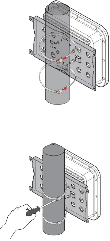
Pole Mount Option
Wall Mount Option
AWB5141

|
Antenna Connectors |
|||
|
AWB5141 |
AWB5142 |
||
|
|
|
||
|
ANT 1 |
WLAN 1, RP-SMA connector, female |
ANT 1 |
WLAN 1, N-type connector, female |
|
ANT2 |
WLAN 2, RP-SMA connector, female |
ANT2 |
WLAN 2, N-type connector, female |
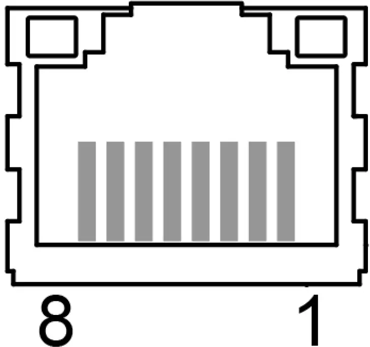
| RJ45 | 10/100 Mbit/s | 1 Gbit/s |
| 1 | TD+ | DA+ |
| 2 | TD- | DA- |
| 3 | RD+ | DB+ |
| 4 | (N/C) | DC+ |
| 5 | (N/C) | DC- |
| 6 | RD- | DB- |
| 7 | (N/C) | DD+ |
| 8 | (N/C) | DD- |
|
Power and PoE Connectors |
|
|
AWB5141 |
|
|
|
|
P- |
10-60 VDC, max. 11.5 W |
|
P+- |
|
|
2 PD |
48 VDC, max 11.5 W IEEE 802.3af PD |
|
AWB5142 |
|
|
|
| WAN/PoE 1 Gbit/sPoE enabled according to 802.3af P.D. |
Safety and Compliance Information
General Safety Instructions
CautionEnsure that the power supply is turned off before connecting it to the equipment.
Connecting power with reverse polarity or using the wrong type of power supply may damage the equipment. Make sure that the power supply is connected correctly and of the recommended type.
This equipment contains parts that can be damaged by electrostatic discharge (ESD). Use ESD prevention measures to avoid damage.
To avoid system damage, the equipment should be connected to ground.
Intended Use
The intended use of this equipment is to provide wireless LAN connectivity. The equipment receives and transmits data on various physical levels and connection types.If this equipment is used in a manner not specified by the manufacturer, the protection provided by the equipment may be impaired.
Radio Regulations
To comply with the European Radio Equipment Directive (RED) and local radio regulations you must configure the country/region settings before the equipment is brought into use. Refer to the user manual for instructions on how to configure the country/region settings.
Installation
Installing AWB5141 IP30 Version
- Mount the device on a standard DIN rail using the included DIN clip.
- Establish a direct connection between the ground screw and a grounding surface.
- Connect the antennas.
- Connect Ethernet.
- Connect power via Ethernet or using the included plug connector.
Installing AWB5142 IP67 Version
- Mount the device on a pole or wall.
- Connect the antennas.
- Connect Ethernet.
- Connect power via Ethernet.
Refer to the user manual for further instructions.
Technical Specifications
| Order Codes |
AWB5141: WLAN AP, IP30, with mesh |
AWB5142: WLAN AP, IP67, with mesh |
| Ethernet connector |
RJ45 |
|
| Power supply |
10-60 VDC (terminal block) or IEEE 802.3af (48 VDC PoE) Max. 11.5 W |
IEEE 802.3af (48 VDC PoE) Max. 11.5 W |
| WLAN 2.4 GHz |
Maximum RF transmitted power:IEEE 802.11b: 21 ±2 dBmIEEE 802.11g: 22 ±2 dBmIEEE 802.11n: 21 ±2 dBm |
|
| WLAN 5 GHz |
Maximum RF transmitted power:IEEE 802.11a: 21.5 ±2 dBmIEEE 802.11an: 21.5 ±2 dBmIEEE 802.11ac: 21.5 ±2 dBm |
|
| Dimensions(W x H x D) |
200 x 51 x 126 mm without DIN mounting clip |
269 x 239 x 68 mm without bracket |
| Weight |
660 g |
2400 g |
| Housing material |
Metal |
|
| IP protection class |
IP30 |
IP67 |
| Mounting |
DIN rail mount |
Pole/Wall mount |
| Operating temperature |
-40 °C to 70 °C, 5–95 % RH non-condensing |
Additional technical data and information related to the installation and use of this product can be found at www.anybus.com/support.
CE Compliance
This product is in compliance with the Radio Equipment Directive 2014/ 53/EU and the RoHS Directive 2011/65/EU with amendment 2015/863 through conformance with applicable standards. The full text of the Declaration of Conformity is available at www.anybus.com/support
Disposal and Recycling
You must dispose of this equipment properly according to local laws and regulations. Because this equipment contains electronic components, it must be disposed of separately from household waste. When this equipment reaches its end of life, contact local authorities to learn about disposal and recycling options, or return the equipment to HMS. For more information, see www.hms-networks.com.
FCC Compliance
This product contains FCC ID: 2ACNTAWB51415142
UL Ordinary Locations (OrdLoc)
This equipment is certified for use in ordinary locations in compliance with the following standards:
- CAN/CSA-C22.2 62368-1-14 Audio/video, information and communication technology equipment – Part 1: Safety requirements
- BS EN 62368-1:2014+A11:2017 Audio/video, information and communication technology equipment – Part 1: Safety requirements
- UL62368-1 Standard for Audio/video, information and communication technology equipment – Part 1: Safety requirements
- AS/NZS 1:2018 Audio/video, information and communication technology equipment – Part 1: Safety requirements
- IEC 62368-1:2014 (ED. 2.0)
- J62368-1 (H30) Japanese Language – AUDIO/VIDEO, INFORMATION AND COMMUNICATION TECHNOLOGY EQUIPMENT – PART 1: SAFETY REQUIREMENTS
The certification number of Anybus Infrastructure products according to OrdLoc certification is: E514162
According to the standards listed above, Anybus Industrial WLAN/LTE Routers are certified with the following marking:
2021 HMS Industrial NetworksBox 4126, 300 04 Halmstad, SwedenSP2803 1.0 / 2021-01-22 / 21351
References
[xyz-ips snippet=”download-snippet”]