
![]()
Anybus® Industrial WLAN/LTE RouterSTARTUP GUIDESP2557 1.11 en-US ENGLISH
![]()
Important User Information
DisclaimerThe information in this document is for informational purposes only. Please inform HMS Industrial Networks of any inaccuracies or omissions found in this document. HMS Industrial Networks disclaims any responsibility or liability for any errors that may appear in this document.HMS Industrial Networks reserves the right to modify its products in line with its policy of continuous product development. The information in this document shall therefore not be construed as a commitment on the part of HMS Industrial Networks and is subject to change without notice. HMS Industrial Networks makes no commitment to update or keep current the information in this document.The data, examples and illustrations found in this document are included for illustrative purposes and are only intended to help improve understanding of the functionality and handling of the product. In view of the wide range of possible applications of the product, and because of the many variables and requirements associated with any particular implementation, HMS Industrial Networks cannot assume responsibility or liability for actual use based on the data, examples or illustrations included in this document nor for any damages incurred during installation of the product. Those responsible for the use of the product must acquire sufficient knowledge in order to ensure that the product is used correctly in their specific application and that the application meets all performance and safety requirements including any applicable laws, regulations, codes and standards. Further, HMS Industrial Networks will under no circumstances assume liability or responsibility for any problems that may arise as a result from the use of undocumented features or functional side effects found outside the documented scope of the product. The effects caused by any direct or indirect use of such aspects of the product are undefined and may include e.g. compatibility issues and stability issues.
Preface
- About This DocumentThis manual describes how to install Anybus Industrial WLAN Router/ Anybus Industrial LTE Router and set up a basic configuration.For additional documentation and software downloads, FAQs, troubleshooting guides and technical support, please visit www.anybus.com/support.
- Document ConventionsThe following conventions are used to indicate safety information and other important content in this document:
 WARNINGInstruction must be followed to avoid a risk of death or serious injury. CautionInstruction must be followed to avoid a risk of personal injury.Instruction that must be followed to avoid a risk of reduced functionality and/or damage to the equipment, or to avoid a network security risk.Additional information which may facilitate installation and/or operation.
 - TrademarksAnybus® is a registered trademark of HMS Industrial Networks. All other trademarks mentioned in this document are the property of their respective holders.
Safety
- Intended UseThe intended use of this equipment is as a communication interface and gateway. The equipment receives and transmits data on various physical levels and connection types.If this equipment is used in a manner not specified by the manufacturer, the protection provided by the equipment may be impaired.
- General Safety CautionEnsure that the power supply is turned off before connecting it to the equipment.Connecting power with reverse polarity or using the wrong type of power supply may damage the equipment. Make sure that the power supply is connected correctly and of the recommended type.This equipment contains parts that can be damaged by electrostatic discharge (ESD). Use ESD prevention measures to avoid damage.To avoid system damage, the equipment should be connected to ground.
Preparation
- Package Checklist
Item Pieces Anybus Industrial WLAN Router/Anybus Industrial LTE Router 1 4 pin terminal block 1 DIN rail clip 1 Startup Guide 1 Safety and Regulatory Compliance Sheet 1
Installation
- Installing Cellular SIM CardApplicable for the LTE router.Install a SIM card in the router to connect it to a cellular data network.Ensure that the SIM card is installed correctly to avoid damage to the SIM card or the router.Procedure1. Loosen the screw locking the SIM card cover, located at the back of the router, and remove the cover.Installing SIM 1:2. Grab hold of the SIM card tray and pull straight out.3. Place a SIM card in the SIM card tray, following the mechanical printout of the tray.4. Place the SIM card tray with the pinhole facing in the right direction and carefully re-insert the tray.Installing SIM 2:5. To use dual SIM cards, repeat step 2 to 4.6. Remount the SIM card cover and fasten the screw.
- Wall Mounting OptionProcedure1. Use the four hook holes at the corners of the wall mounting bracket to hang the router on the wall.
- DIN Rail Mounting OptionMount the router on a DIN rail in accordance with the EN 50022 standard.Procedure1. Fasten the DIN clip with 3 (M3x6 flat head) screws on the rear side of the router.Mount the router on a DIN rail:2. Insert the upper end of the DIN rail clip into the DIN rail.3. Push the bottom of the DIN rail clip into the DIN rail.
- Connecting Ground ScrewTo avoid system damage, the equipment should be connected to ground.Procedure1. Establish a direct connection between the ground screw and the grounding surface prior to connecting devices.
- Terminal Block
Contact Number Description 1 Power Input V+ 2 Power Input V– 3 DO, Digital Output 4 Description - Installing Terminal BlockProcedure1. Attach the 4 pin terminal block to the contact on the router.2. Fasten the terminal block with the 2 screws included.
- Connecting Digital Output WiresBefore You BeginThe relay output are used to detect user-configured events. When a user-configured event is triggered, the two wires attached to the DO, fault contacts, form a close circuit.The fault circuit remains opened until a user-configured event occur.ProcedureConnect the Digital Output (DO):1. Insert the wires into the 2 pin DO contact on the 4 pin terminal block.2. Tighten the wire-clamp screws.
- Connecting Power WiresCautionEnsure that the power supply is turned off before connecting it to the equipment.Use a power supply of 8-32 VDC to power the router. Max power consumption: 11.2 W.The relay contact supports 0.5 A current, 24 VDC.ProcedureConnect the router to power:1. Attach the terminal block connector to the router.2. Insert the positive and negative wires into the V+ and V- contact on the terminal block connector.3. Tighten the wire-clamp screws.4. Connect the power wires to a DC switching type power supply.
- Connecting to Ethernet NetworkOptionalConnect the router to an Ethernet network via the WAN port 9.
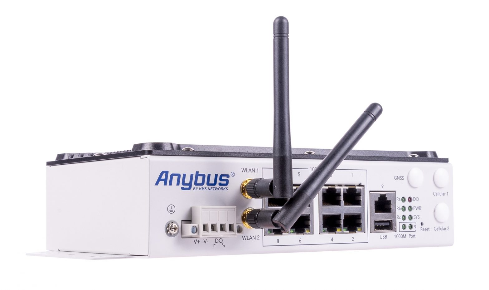
- Connecting AntennasFig. 1 Antenna connectorsPlacement of the antennas
Router Model Placement Type Anybus Industrial WLAN Router A WLAN 1 B WLAN 2 Anybus Industrial LTE Router C GPSGNSS D Cellular 1LTE-Main E Cellular 2LTE-Aux
 1. Loosen the screw locking the SIM card cover, located at the back of the router, and remove the cover.Installing SIM 1:2. Grab hold of the SIM card tray and pull straight out.3. Place a SIM card in the SIM card tray, following the mechanical printout of the tray.4. Place the SIM card tray with the pinhole facing in the right direction and carefully re-insert the tray.Installing SIM 2:5. To use dual SIM cards, repeat step 2 to 4.6. Remount the SIM card cover and fasten the screw.
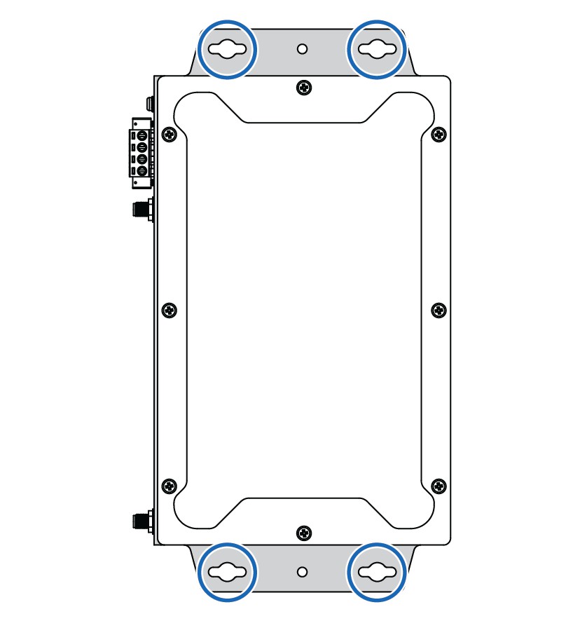 1. Use the four hook holes at the corners of the wall mounting bracket to hang the router on the wall.
 1. Fasten the DIN clip with 3 (M3x6 flat head) screws on the rear side of the router.
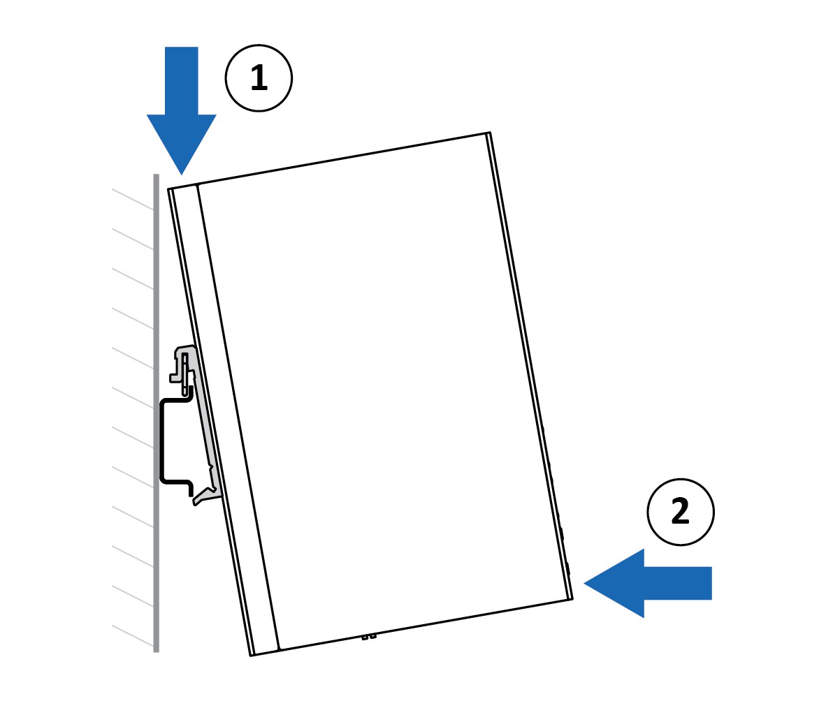 Mount the router on a DIN rail:2. Insert the upper end of the DIN rail clip into the DIN rail.3. Push the bottom of the DIN rail clip into the DIN rail.
 1. Establish a direct connection between the ground screw and the grounding surface prior to connecting devices.
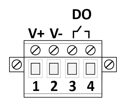
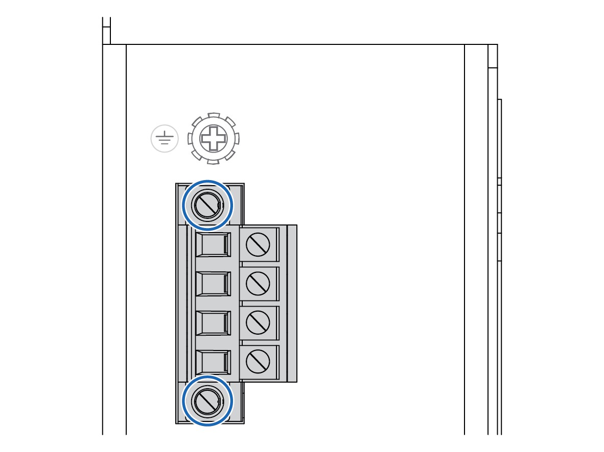 1. Attach the 4 pin terminal block to the contact on the router.2. Fasten the terminal block with the 2 screws included.
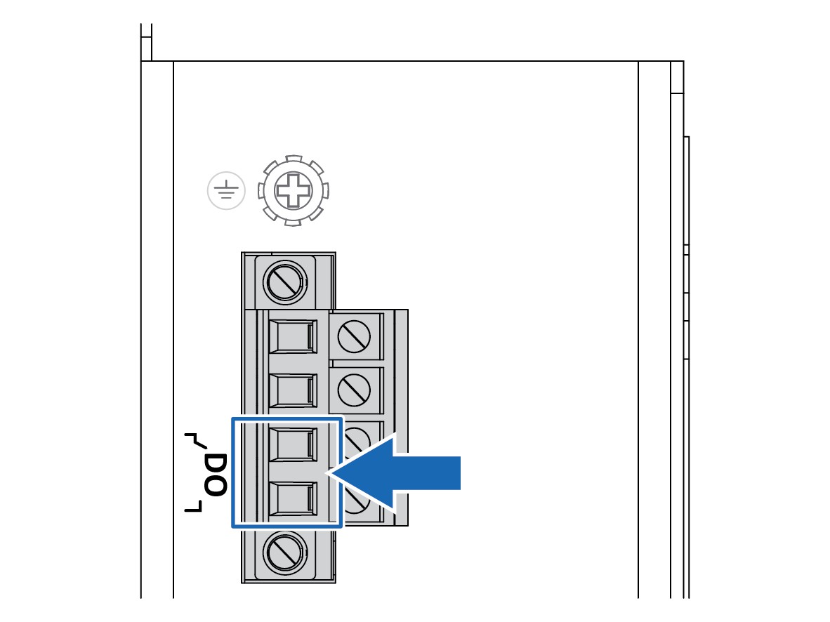 1. Insert the wires into the 2 pin DO contact on the 4 pin terminal block.2. Tighten the wire-clamp screws.
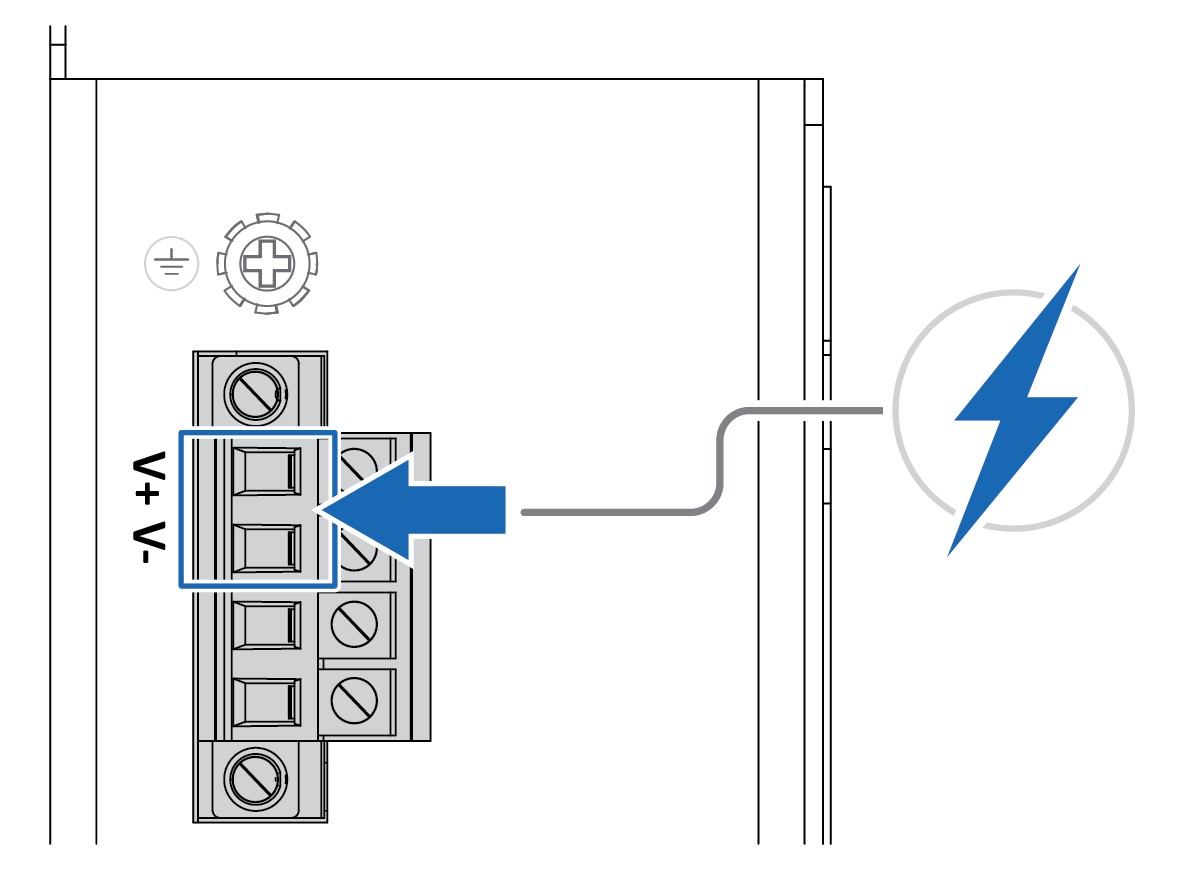 1. Attach the terminal block connector to the router.2. Insert the positive and negative wires into the V+ and V- contact on the terminal block connector.3. Tighten the wire-clamp screws.4. Connect the power wires to a DC switching type power supply.
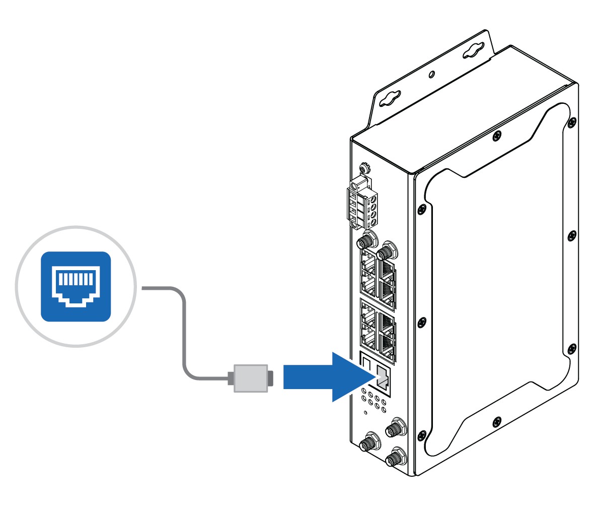
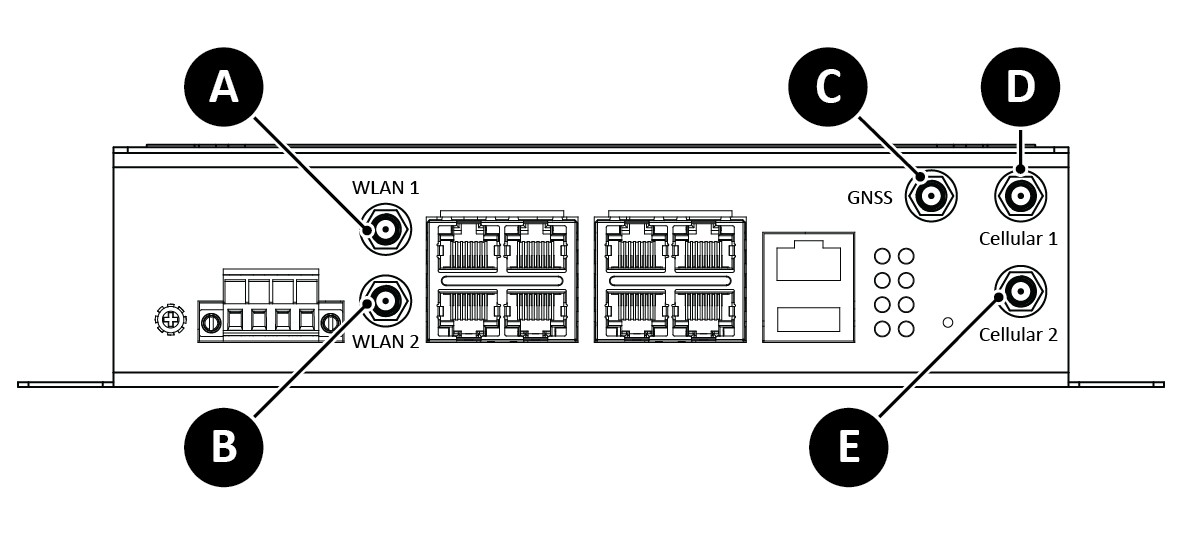 Fig. 1 Antenna connectorsPlacement of the antennas
Configuration
- Before You Begin ConfigurationThe router is configured through web management.The router default IP address is http://192.168.10.1/.The default router login user name and password is admin.
- Web ManagementPrepare for configuring the router settings via the web management interface.Before You Begin• To link your computer with the router, make sure that the IP address of the computer is located in the same subnet as the router default IP address.ProcedureAccess the web management interface:1. In your browser, type http://IP address and press Enter.→ The web-based management interface login screen appears.2. In the login screen, enter user name and password.3. Click OK.→ The web-based management interface welcome page appears.To Do Next• Configure the router.Follow the instructions in the user manual.
- Configure the Country/Region SettingsApplicable for the WLAN router.To comply with the Radio Equipment Directive (RED) and local radio regulations you must configure the country/region settings before the router is brought into use.ProcedureConfigure the Country settings.In the web management interface:1. Navigate to the WLAN Settings tab.2. Select your country/region from the Country drop-down menu.3. Press Submit button for the setting to take effect.
- USB PortUse the USB port in order to save or restore the configuration and upload the firmware upgrade file.For further configurations, refer to the User Manual.
- Factory ResetProcedureTo reset the router to its factory settings:1. Ensure that the router is powered on.2. Use a pointed object (such as a ballpoint pen) to press and hold the reset button for >10 seconds.Result→ Once the reset button is released, the router reboot automatically.→ When the router has successfully rebooted, the SYS LED turns green.
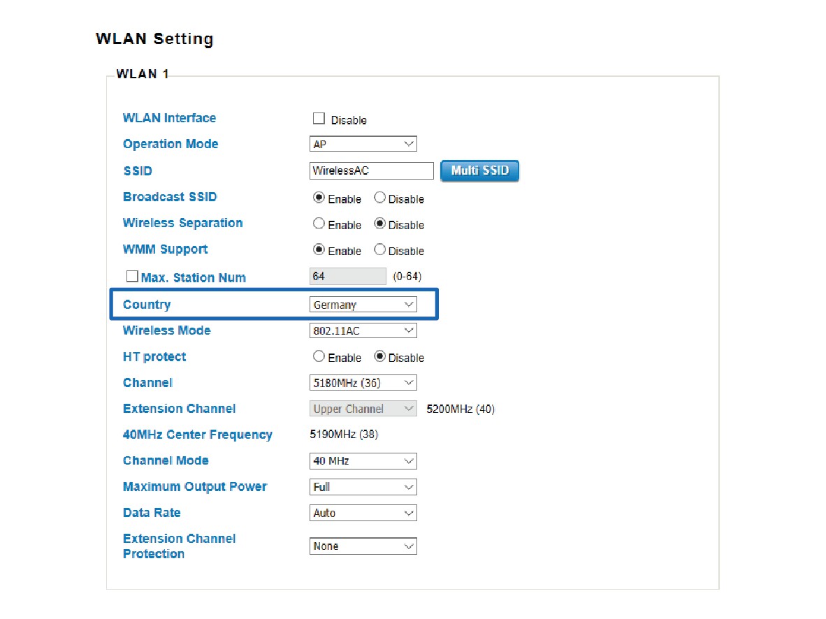 In the web management interface:1. Navigate to the WLAN Settings tab.2. Select your country/region from the Country drop-down menu.3. Press Submit button for the setting to take effect.
 For further configurations, refer to the User Manual.
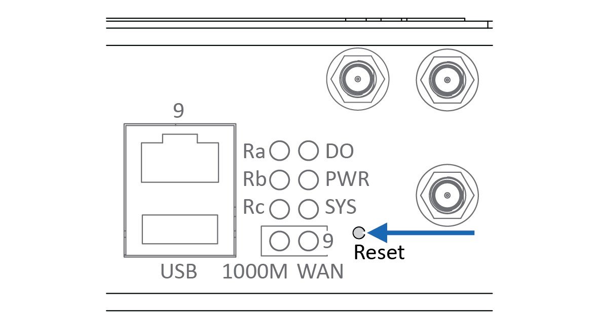 ProcedureTo reset the router to its factory settings:1. Ensure that the router is powered on.2. Use a pointed object (such as a ballpoint pen) to press and hold the reset button for >10 seconds.Result→ Once the reset button is released, the router reboot automatically.→ When the router has successfully rebooted, the SYS LED turns green.
Verify Operation
When the installation and configuration are completed, verify that the router is in operation.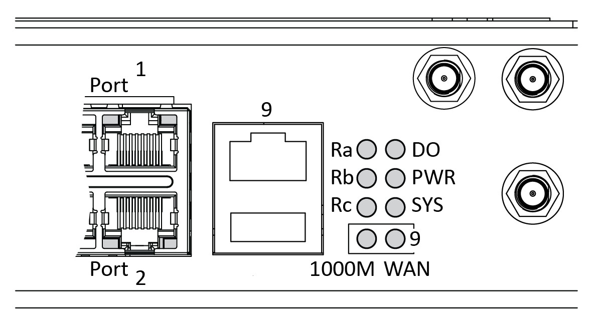 Fig. 2 LED Indicators
Front Panel LED
| LED | Status | Description |
| PWR | Green On | DC-IN Power is On |
| Off | No Power in DC-IN | |
| SYS
System LED |
Green On | Ready |
| Green Blinking | Firmware Updating | |
| Off | Not Ready | |
| DO
Alarm |
Red On | Any failure in port link by SW control |
| Off | No failure occurs | |
| 1000 MWAN | Green On | WAN port speed is 1 Gbit/s |
| Off | WAN port speed is not 1 Gbit/s | |
| Port 9WAN | Green On | Link is established |
| Green Blinking | Packets transmitting/receiving |
RJ45 LED
| LED | Status | Description |
| Port 1–8 | Green On | Link is established |
| Green Blinking | Packets transmitting/receiving | |
| Off | Link is inactive |
Radio LED
| LED | Router Model | Status | Description |
| Ra | LTE | Green On | SIM detected |
| Off | SIM not detected | ||
| WLAN | Reserved | Reserved for future use | |
| Rb | LTE | Green On | 4G connection |
| Green
blinking |
2/3G connection | ||
| Off | Disconnected | ||
| WLAN | Reserved | Reserved for future use | |
| Rc | LTE | Reserved | Reserved for future use |
| WLAN | Green On | AP mode | |
| Green
blinking |
STA connected | ||
| Off | STA disconnected
Radio disabled |
Technical Data
- Technical Specifications
Order Codes AWB5121 (WLAN Router)AWB5221 (LTE Router) Cellular standards LTE Cat.4 2×2 MIMO, 4G/3G/2G Fall BackLTE-FDD: B1/B2/B3/B4/B5/B7/B8/B12/B13/B18/B19/B20/B25/B26/B28LTE-TDD: B38/B39/B40/B41WCDMA: B1/B2/B4/B5/B6/B8/B19 Ethernet Ports LAN: 8 x 10/100Base-TX RJ45, Auto Negotiation, Auto MDI/MDI-X WAN: 1 x 100/1000Base-T RJ45, Auto Negotiation, Auto MDI/MDI-X Operating temperature -40°C to 75°C , 5%-95% Non- Condensing Data speeds LTE:GPRS: DL: max. 85.6 kbps, UL: max. 85.6 kbpsEDGE: DL: max. 236.8 kbps, UL: max. 236.8 kbpsHSPA: DL: max. 42 Mbps, UL: max. 5.76 MbpsLTE-FDD Cat.4: DL: max. 150 Mbps, UL: max. 50 Mbps, 2×2DL MIMOLTE-TDD Cat.4: DL: max. 130 Mbps, UL: max. 35 Mbps, 2×2DL MIMOWLAN:802.11ac: MCS0 – 9, max. 866 Mbps802.11b: 11Mbps / 802.11a/g: 54Mbps / 802.11n: MCS0 – 15,max. 300Mbps Power 8-32 VDCMax. 11.2 W4-Pin Removable Terminal Block Connector2 Pin for Power Input2 Pin for DODO: Dry Relay Output – Max 0.5A/24V DC Weight 1400 g Housing material Steel & Aluminum For more information, refer to datasheet at www.anybus.com/support.
© 2020 HMS Industrial NetworksBox 4126300 04 Halmstad, Sweden[email protected]SP2557 1.11 en-US / 2020-03-13 / 17649
References
[xyz-ips snippet=”download-snippet”]