![]()
Anybus® Wireless BoltTM IoTSTARTUP GUIDESP2727 1.11 en-US
![]()
![]()
Important User Information
DisclaimerThe information in this document is for informational purposes only. Please inform HMS Networks of any inaccuracies or omissions found in this document. HMS Networks disclaims any responsibility or liability for any errors that may appear in this document.HMS Networks reserves the right to modify its products in line with its policy of continuous product development. The information in this document shall therefore not be construed as a commitment on the part of HMS Networks and is subject to change without notice. HMS Networks makes no commitment to update or keep current the information in this document.The data, examples, and illustrations found in this document are included for illustrative purposes and are only intended to help improve understanding of the functionality and handling of the product. In view of the wide range of possible applications of the product, and because of the many variables and requirements associated with any particular implementation, HMS Networks cannot assume responsibility or liability for actual use based on the data, examples, or illustrations included in this document nor for any damages incurred during the installation of the product. Those responsible for the use of the product must acquire sufficient knowledge in order to ensure that the product is used correctly in their specific application and that the application meets all performance and safety requirements including any applicable laws, regulations, codes, and standards. Further, HMS Networks will under no circumstances assume liability or responsibility for any problems that may arise as a result of the use of undocumented features or functional side effects found outside the documented scope of the product. The effects caused by any direct or indirect use of such aspects of the product are undefined and may include e.g. compatibility issues and stability issues.
Preface
1.1 About This DocumentThis manual describes how to install and configure Anybus Wireless Bolt IoT.For additional documentation and software downloads, FAQs, troubleshooting guides, and technical support, please visit www.anybus.com/support.
1.2 Document ConventionsNumbered lists indicate tasks that should be carried out in sequence:
- First, do this
- Then do this
Bulleted lists are used for:
- Tasks that can be carried out in any order
- Itemized information► An action→ and a result
User interaction elements (buttons etc.) are indicated with bold text.Program code and script examplesCross-reference within this document: Document Conventions, p. 4External link (URL): www.hms-networks.com
![]() WARNINGInstruction that must be followed to avoid a risk of death or serious injury.
WARNINGInstruction that must be followed to avoid a risk of death or serious injury.
![]() CautionInstruction must be followed to avoid a risk of personal injury.
CautionInstruction must be followed to avoid a risk of personal injury.
![]() Instruction that must be followed to avoid a risk of reduced functionality and/or damage to the equipment, or to avoid a network security risk.
Instruction that must be followed to avoid a risk of reduced functionality and/or damage to the equipment, or to avoid a network security risk.
![]() Additional information which may facilitate installation and/or operation.
Additional information which may facilitate installation and/or operation.
1.3 TrademarksAnybus®is a registered trademark and Wireless Bolt IoT™ is a trademark of HMSIndustrial Networks AB. All other trademarks mentioned in this document are the property of their respective holders.
Safety
2.1 General Safety Instructions
![]() CautionThis equipment emits RF energy in the ISM (Industrial, Scientific, Medical) band. Make sure that all medical devices used in proximity to this equipment meet appropriate susceptibility specifications for this type of RF energy.
CautionThis equipment emits RF energy in the ISM (Industrial, Scientific, Medical) band. Make sure that all medical devices used in proximity to this equipment meet appropriate susceptibility specifications for this type of RF energy.
![]() This equipment is recommended for use in both industrial and domestic environments. For industrial environments, it is mandatory to use the functional earth connection to comply with immunity requirements. For domestic environments, the functional earth must be used if a shielded Ethernet cable is used, in order to meet emission requirements.
This equipment is recommended for use in both industrial and domestic environments. For industrial environments, it is mandatory to use the functional earth connection to comply with immunity requirements. For domestic environments, the functional earth must be used if a shielded Ethernet cable is used, in order to meet emission requirements.
![]() This equipment contains parts that can be damaged by electrostatic discharge (ESD). Use ESD prevention measures to avoid damage.
This equipment contains parts that can be damaged by electrostatic discharge (ESD). Use ESD prevention measures to avoid damage.
2.2 Intended UseThe intended use of this equipment is as a communication interface and router.The equipment receives and transmits data over Ethernet and Cellular standard networks.
Installation
3.1 Installing SIM Card
![]() Supported SIM card types are Nano-SIM for IoT and M2M, for data communication, as well as standard mobile phone Nano-SIM.
Supported SIM card types are Nano-SIM for IoT and M2M, for data communication, as well as standard mobile phone Nano-SIM.
![]()
To connect Wireless Bolt IoT to a cellular data network, install a cellular SIM card:
- Insert a SIM card into the Wireless Bolt IoT SIM cardholder.
 Ensure that the SIM card contact surface is facing towards the Ethernet port.
3.2 Mechanical Installation
Placement
- The device is intended to be mounted on top of a machine or cabinet through an M50 (50.5 mm) hole using the included sealing ring and nut.
- The top mounting surface, in contact with the sealing, must be flat with a finish equivalent to Ra 3.2 or finer and cleaned and free from oils and greases.
- For optimal reception, cellular devices require a zone around them clear of objects that could obstruct or reflect the signal. To avoid interference, a minimum distance of 50 cm between Wireless Bolt IoT and other cellular devices should be observed.Make sure that the sealing ring is correctly placed in the circular groove in the top part of the housing before tightening the nut.Always hold the BOTTOM part of the unit when untightening the nut, not the top part (the cap).
Tightening torque: 5 Nm ±10 %
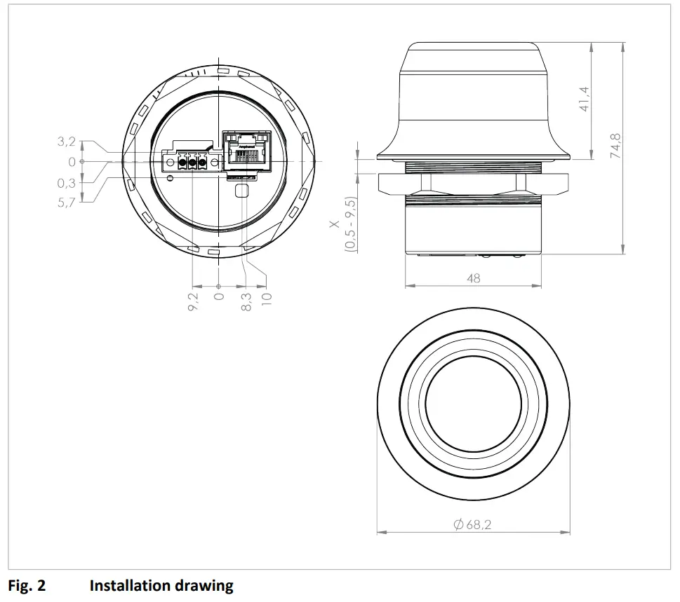
All measurements are in mm.
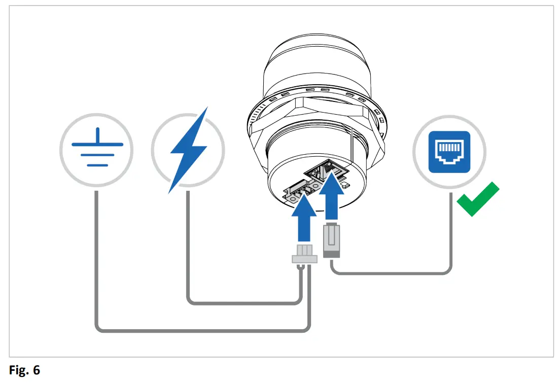
3.3 Connecting to Ethernet/Power Over Ethernet (PoE)Before You Begin
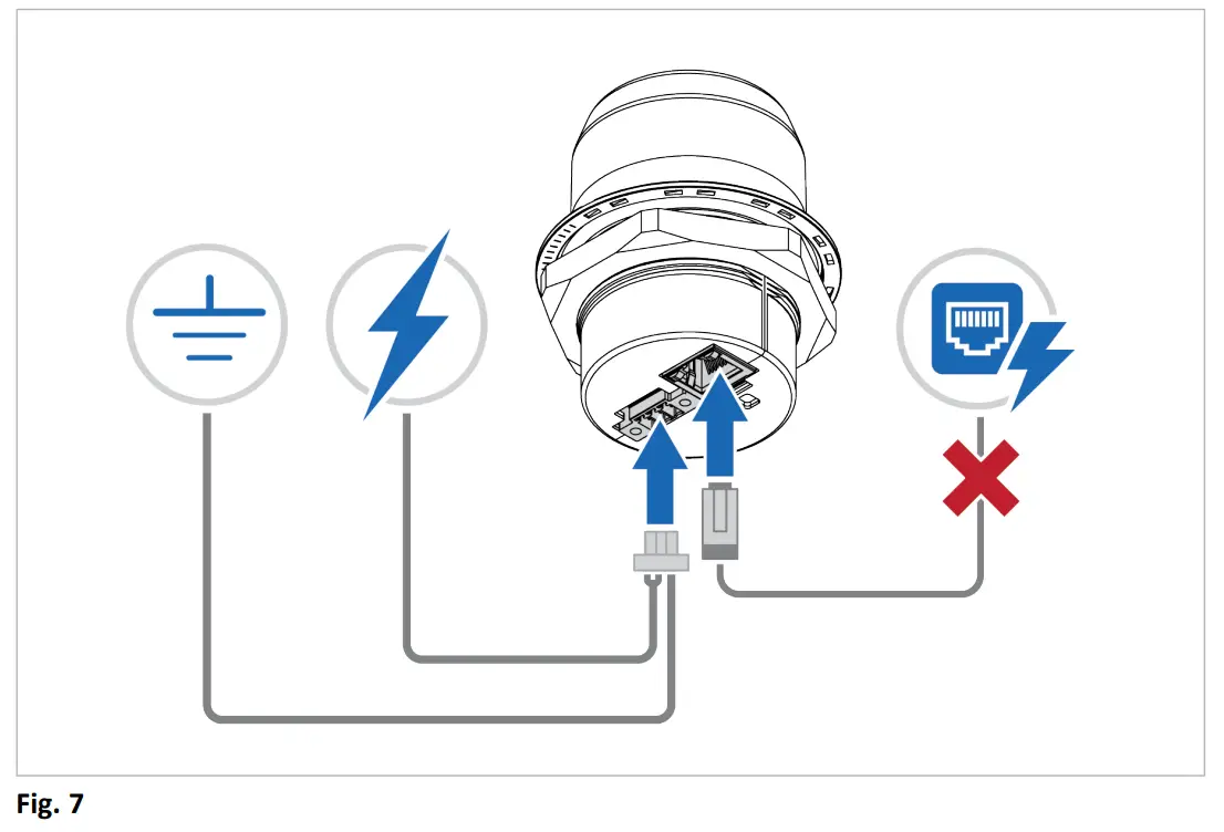
![]() Connecting the Wireless Bolt IoT to PoE and DC power simultaneously may result in a current loop that could damage both the power sources and the Wireless Bolt IoT. Ensure to use only one of the power connections at a time.
Connecting the Wireless Bolt IoT to PoE and DC power simultaneously may result in a current loop that could damage both the power sources and the Wireless Bolt IoT. Ensure to use only one of the power connections at a time.![]() Shielded or unshielded Ethernet cables may be used.
Shielded or unshielded Ethernet cables may be used.![]() Wireless Bolt IoT is designed to comply with PoE class 0 (37-57 VDC, max 0.35A), according to IEEE 802.3.
Wireless Bolt IoT is designed to comply with PoE class 0 (37-57 VDC, max 0.35A), according to IEEE 802.3.
Procedure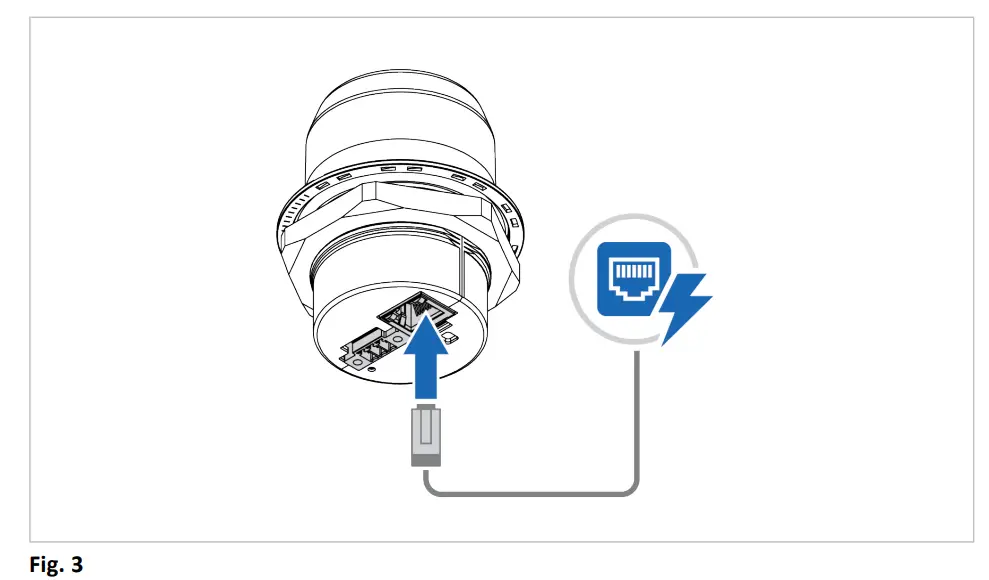
- Connect the Wireless Bolt IoT Ethernet port to Ethernet/PoE.
Ethernet Connector, RJ45 PoE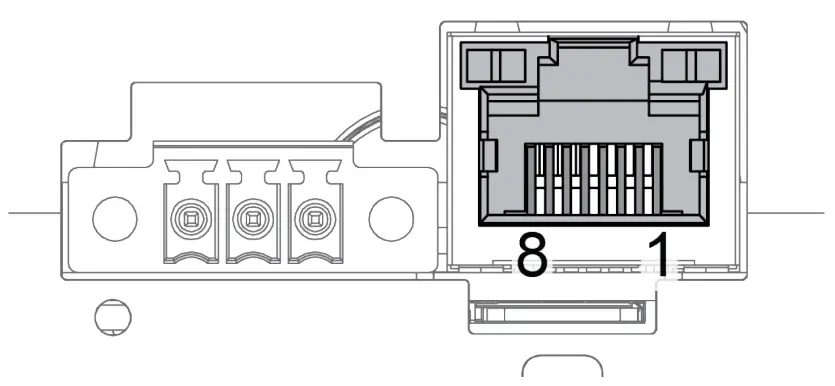
| Pin | Data | PoE | |
| 1 | TD+ | A+ | Positive power from alt. A PSE |
| 2 | TD- | A- | Negative power from alt. A PSE (with pin 6) |
| 3 | RD+ | ||
| 4 | B+ | Positive power from alt. B PSE | |
| 5 | |||
| 6 | RD- | A- | Negative power from alt. A PSE (with pin 3) |
| 7 | B- | Negative power from alt. B PSE | |
| 8 | |||
| Housing | Shield | Functional Earth (FE), via 1 nF capacitor and 1 MΩ bleeder resistor |
3.4 Connecting to PowerBefore You Begin
![]() Connecting power with reverse polarity or using the wrong type of power supply may damage the equipment. Make sure that the power supply is connected correctly and of the recommended type.
Connecting power with reverse polarity or using the wrong type of power supply may damage the equipment. Make sure that the power supply is connected correctly and of the recommended type.![]() When Wireless Bolt IoT is powered via the power connector, Functional Earth (FE) must be connected.
When Wireless Bolt IoT is powered via the power connector, Functional Earth (FE) must be connected.![]() When Wireless Bolt IoT is installed in an environment with a high level of electrical noise, use a power/Functional Earth (FE) cable with a maximum length of 3 meters.
When Wireless Bolt IoT is installed in an environment with a high level of electrical noise, use a power/Functional Earth (FE) cable with a maximum length of 3 meters.
See also Technical Data, p. 18 regarding power supply requirements.
Functional earth wire screw placement

When Wireless Bolt IoT is mounted on a sheet metal plate, connect Functional Earth (FE) to the plate near Wireless Bolt IoT.
Procedure
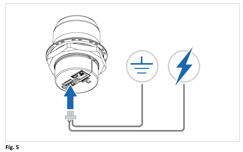
- Connect Wireless Bolt IoT Power connector to a power supply.
- Connect Wireless Bolt IoT Power connector to Functional Earth (FE).
Power connector, 3-pin terminal block
| Pin | Function | |
| 1 | + | 11–33 VDC |
| 2 | _ | |
| 3 | Functional Earth (FE) |
To-Do Next► Connect the Wireless Bolt IoT to Ethernet.
Connecting the Wireless Bolt IoT to PoE and DC power simultaneously may result in a current loop that could damage both the power sources and the Wireless Bolt IoT. Ensure to use only one of the power connections at a time.
Configuration
Wireless Bolt IoT Built-In Web Interface
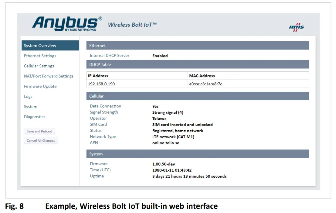
The Wireless Bolt IoT built-in web interface is used to configure theWireless Bolt IoT system settings.The System Overview page shows the current settings and network connection status.
Before You Begin![]() The Wireless Bolt IoT comes with a default username and password.The default username is admin. Written in lowercase letters.You find the default password on the Wireless Bolt IoT product housing.
The Wireless Bolt IoT comes with a default username and password.The default username is admin. Written in lowercase letters.You find the default password on the Wireless Bolt IoT product housing.![]() Wireless Bolt IoT default IP address is 192.168.0.98.To access the Wireless Bolt IoT built-in web interface, ensure that theWireless Bolt IoT IP address and your PC IP address are within the same IP address range.
Wireless Bolt IoT default IP address is 192.168.0.98.To access the Wireless Bolt IoT built-in web interface, ensure that theWireless Bolt IoT IP address and your PC IP address are within the same IP address range.
Procedure
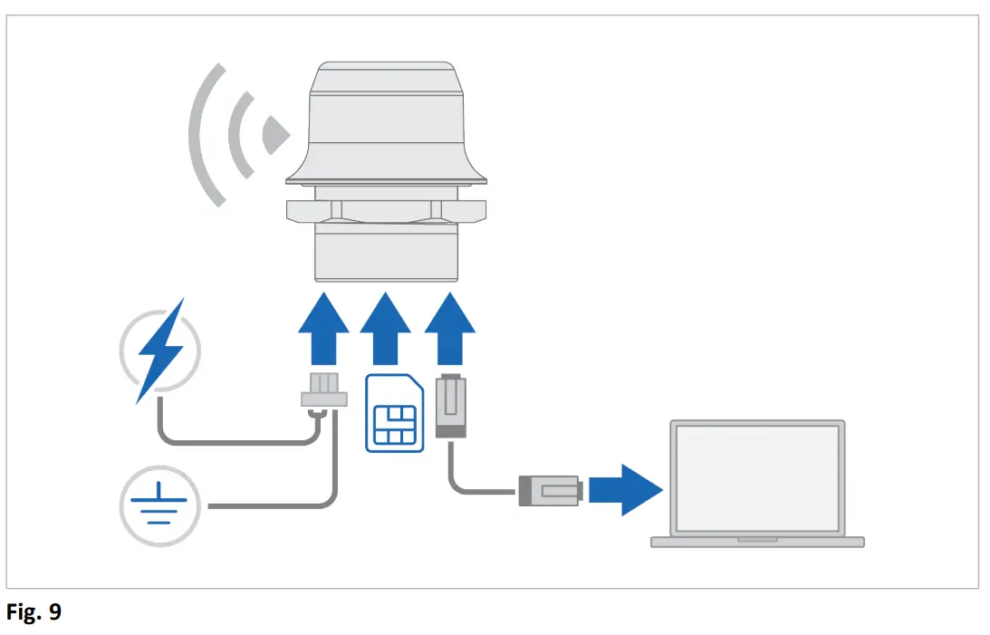
Connecting Wireless Bolt IoT to the internet:
- Insert a cellular SIM card in the Wireless Bolt IoT SIM cardholder.Ensure that the SIM card contact surface is facing towards the Ethernet port.
- Connect the Wireless Bolt IoT Ethernet port to your PC.
- Connect the Wireless Bolt IoT Power connector to a power supply.
- To access the built-in web interface, enter the Wireless Bolt IoT IP address in your web browser and click Enter.
- Login to the Wireless Bolt IoT built-in web interface.
- Configure the Ethernet Settings, IP address, and internal DHCP server settings.
- Verify that the APN Settings are correct. You can adjust the settings manually.
- In the System Overview page, verify that the cellular Data Connection has the status Yes.
- In the left sidebar menu, click Save and Reboot.→ Wireless Bolt IoT automatically reboots for the settings to take effect.
ResultWireless Bolt IoT should now be connected to the internet.![]() Depending on the mobile network operator and network type, it can take up to 10 minutes the first time Wireless Bolt IoT is connecting to the internet.Verify that Wireless Bolt IoT is connected to the internet, by sending a ping to Google Public DNS.
Depending on the mobile network operator and network type, it can take up to 10 minutes the first time Wireless Bolt IoT is connecting to the internet.Verify that Wireless Bolt IoT is connected to the internet, by sending a ping to Google Public DNS.
- On the Diagnostics page, select the Ping method.
- In the Target field, enter the IP address (IPv4)8.8.8.8.
- To Perform Action, click Start.→ The ping request is sent.→ When the ping response returns, a message appears.
![]()
Connecting Devices
Connecting a device to the internet:
- Connect an Ethernet cable between Wireless Bolt IoT and the device.
- Verify that the device is connected to the internet.
Technical Data
5.1 Technical Specifications
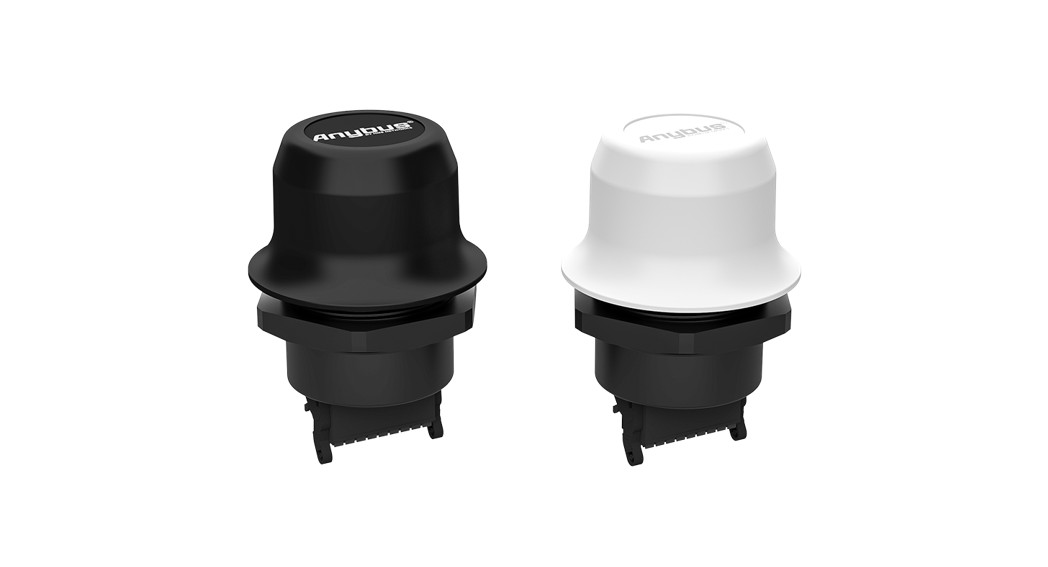
| Order code | AWB1000 | AWB1001 |
| Color | Black | Whitetop and black base |
| Operating temperature | Shadow: -40 to +65 °C Direct sunlight: -40 to +45 °C | Shadow: -40 to +65 °C Direct sunlight: -40 to +65 °C |
| Host interface | RJ45 Ethernet 10/100 Mbit/s, PoE | |
| Storage temperature | -40 to +85 °C | |
| Humidity compability | EN 600068-2-78: Damp heat, +40 °C, 90% (non-condensing). | |
| Vibration | Refer to datasheet at www.anybus.com/support. | |
| Dimensions | Diameter: 68 mm.Height: 75 mm without Power connector, 84 mm incl. Power connector.Height above mounting surface: 41 mm. | |
| Weight | 95 g | |
| Housing material | Plastic (see datasheet for details) | |
| Protection class | Top (outside of the host): IP66 and IP67 / UL NEMA 4X Base (inside of host): IP21 | |
| Mounting | M50 screw and nut (50.5 mm hole needed) | |
| Power | 3-pin screw connector and PoE (Power over Ethernet) 11-33 VDC through Power connector, PoE PD according to IEEE 802.3af through Ethernet connector.Redundant or separate operation of PoE and DC connectors.Power Consumption:Sleep Mode: Power connector 0.1 W. PoE 0.3 W Idle Mode: Power connector 0.6 W. PoE 0.8 W Worst Case (GPRS/2G) average power: Power connector 3.2 W. PoE 3.6 W.Worst case (GPRS/2G) peak current: | |
| Cellular standards | 4G LTE: Category Cat-M1 and NB-loT. |
| Order code | AWB1000 | AWB1001 |
| Frequency Bands: Bl, 82, B3, B4, 85, 88, 512, 813,B17, 518, B19, 820, 826, 8282G: EDGE, GPRS bands 850, 900, 1800, 1900 | ||
| Maximum Data speeds | Cat-M1: Download 300 kbps, Upload 375 kbpsNB-loT: Download 27 kbps, Upload 65 kbpsGPRS/EDGE Download: 200 kbps, Upload: 200 kbps. | |
| Ethernet protocols | Transparent transfer of any TCP/UDP based protocol,Built-in firewall, NAT, and DHCP server. | |
| Certifications | Refer to datasheet at www.anybus.com/support. |
This page intentionally left blank
An Ethernet LED Status Indication
 report this ad
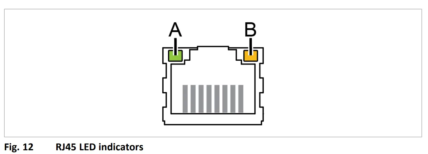
| LED A — LINK/ACTIVITY | Function |
| Off | No Ethernet link |
| Yellow | 10 Mb/s Ethernet link established |
| Yellow, flashing | 10 Mb/s Ethernet activity |
| Green | 100 Mb/s Ethernet link established |
| Green, flashing | 100 Mb/s Ethernet activity |
| LED B — STATUS | Function |
| Off | No power |
| Blue | Connected on LTE-M |
| Purple | Connected on LTE NB1 |
| Blue, slow blink | Connected on GSM. |
| Alternating blue/purple | Trying to connect |
| Red, slow blink | No configured cellular interface/no SIM card/no valid configuration |
| Red | Recoverable/unrecoverable fault |
| Yellow | Booting or sleep |
© 2020 HMS Industrial NetworksBox 4126300 04 Halmstad, Sweden[email protected]SP2727 1.11 en-US / 2020-12-18 / 21155
References
[xyz-ips snippet=”download-snippet”]