Anybus Wireless Bridge II SP2167 User Guide
Important User Information
Disclaimer
The information in this document is for informational purposes only. Please inform HMS Networks of any inaccuracies or omissions found in this document. HMS Networks disclaims any responsibility or liability for any errors that may appear in this document.
HMS Networks reserves the right to modify its products in line with its policy of continuous product development. The information in this document shall therefore not be construed as a commitment on the part of HMS Networks and is subject to change without notice. HMS Networks makes no commitment to update or keep current the information in this document.
The data, examples and illustrations found in this document are included for illustrative purposes and are only intended to help improve understanding of the functionality and handling of the product. In view of the wide range of possible applications of the product, and because of the many variables and requirements associated with any particular implementation, HMS Networks cannot assume responsibility or liability for actual use based on the data, examples or illustrations included in this document nor for any damages incurred during installation of the product. Those responsible for the use of the product must acquire sufficient knowledge in order to ensure that the product is used correctly in their specific application and that the application meets all performance and safety requirements including any applicable laws, regulations, codes and standards. Further, HMS Networks will under no circumstances assume liability or responsibility for any problems that may arise as a result from the use of undocumented features or functional side effects found outside the documented scope of the product.The effects caused by any direct or indirect use of such aspects of the product are undefined and may include e.g. compatibility issues and stability issues.
About This Document
This document describes how to install Anybus Wireless Bridge II and set up a basic configuration.
For additional documentation, configuration examples, FAQs, troubleshooting guides and technical support, please visit www.anybus.com/support.
Document Conventions
The following conventions are used to indicate safety information and other important content in this document:
![]() WARNINGInstruction that must be followed to avoid a risk of death or serious injury.
WARNINGInstruction that must be followed to avoid a risk of death or serious injury.
![]() CautionInstruction that must be followed to avoid a risk of personal injury.
CautionInstruction that must be followed to avoid a risk of personal injury.
![]() Instruction that must be followed to avoid a risk of reduced functionality and/or damage to the equipment, or to avoid a network security risk.
Instruction that must be followed to avoid a risk of reduced functionality and/or damage to the equipment, or to avoid a network security risk.
![]() Additional information which may facilitate installation and/or operation.
Additional information which may facilitate installation and/or operation.
Trademarks
Anybus® is a registered trademark and Wireless Bridge II™ is a trademark of HMSIndustrial Networks AB. All other trademarks mentioned in this document are the property of their respective holders.
Safety
General Safety Instructions
![]() CautionThis equipment emits RF energy in the ISM (Industrial, Scientific, Medical) band. Make sure that all medical devices used in proximity to this equipment meet appropriate susceptibility specifications for this type of RF energy
CautionThis equipment emits RF energy in the ISM (Industrial, Scientific, Medical) band. Make sure that all medical devices used in proximity to this equipment meet appropriate susceptibility specifications for this type of RF energy
![]() CautionThe M12 power and LAN connectors must be provided with tool operated mechanical lock nuts that are tightened by the installer.
CautionThe M12 power and LAN connectors must be provided with tool operated mechanical lock nuts that are tightened by the installer.
![]() This equipment is recommended for use in both industrial and domestic environments. For industrial environments it is mandatory to use the functional earth connection to comply with immunity requirements. For domestic environments the functional earth must be used if a shielded Ethernet cable is used, in order to meet emission requirements.
This equipment is recommended for use in both industrial and domestic environments. For industrial environments it is mandatory to use the functional earth connection to comply with immunity requirements. For domestic environments the functional earth must be used if a shielded Ethernet cable is used, in order to meet emission requirements.
![]() This equipment contains parts that can be damaged by electrostatic discharge (ESD). Use ESD prevention measures to avoid damage.
This equipment contains parts that can be damaged by electrostatic discharge (ESD). Use ESD prevention measures to avoid damage.
External Antenna Restrictions
For models with external antenna, only use antennas that are certified for use with this equipment. Using external antennas that are not certified for use with this equipment will invalidate its certifications and make it non-compliant with the regulations for radio equipment.
A list of certified antennas can be found at www.anybus.com/support.
Intended Use
The intended use of this equipment is as a communication interface and gateway. The equipment receives and transmits data on various physical levels and connection types.
If this equipment is used in a manner not specified by the manufacturer, the protection provided by the equipment may be impaired.
Type Identification
The type name consists of a type prefix followed by two designators for interface configuration and functionality
| Prefix | AWB3 | Anybus Wireless Bridge II |
| Interface configuration | AB | Internal antenna, Dual M12 External antenna, Dual M12, RP-SMA |
| Functionality | AB | Ethernet with digital input Ethernet w/o digital input |
Example: AWB3AA = Anybus Wireless Bridge II with internal antenna, Ethernetnetworking and digital input.
Installation
General Information
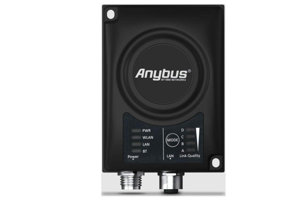
Anybus Wireless Bridge II can be screw-mounted directly onto a flat surface or mounted on a standard DIN rail using the optional DIN mounting kit.
For optimal reception, wireless devices require a zone between them clear of objects that could otherwise obstruct or reflect the signal. A minimum distance of 50 cm between the devices should also be observed to avoid interference.
For models with internal antenna the characteristics of the antenna should be considered when choosing the placement and orientation of the unit. See the User Manual for more information about the antenna characteristics for this equipment.
Make sure that you have all the necessary information about the capabilities and restrictions of your local network environment before installation.
Connectors

Power Connector (A-coded male M12)
|
– |
Pin | Function |
|
|
1 | Power + (9–30 V) |
| 2 | Digital Input Ground | |
| 3 | Power Ground | |
| 4 | Digital Input + (9–30 V) | |
| 5 | Functional Earth |

The digital input can be used for additional functionality with advanced configurations and to remotely reset the unit.
![]() If voltage is applied to the digital input for more that 10 seconds the unit will be reset to factory defaults.
If voltage is applied to the digital input for more that 10 seconds the unit will be reset to factory defaults.
![]() Signal wiring for the digital input must be carried in the same cable as power and functional earth if wiring length exceeds 3 meters.
Signal wiring for the digital input must be carried in the same cable as power and functional earth if wiring length exceeds 3 meters.
See www.anybus.com/support for more information about the digital input.
LAN Connector (D-coded female M12)
|
– |
Pin | Function | Color coding (T568B) |
|
|
1 | Transmit + | Orange/White |
| 2 | Receive + | Green/White | |
| 3 | Transmit – | Orange | |
| 4 | Receive – | Green |

LED Indicators
Status Indicators

| LED Indication | Description | |
| PWR | Off | No power |
| Green | Normal operation | |
| WLAN | Off | WLAN disabled or no power |
| Blue, blinking | Access Point: No clients, awaiting connections | |
| Blue | Access Point: Connected to at least one client
Client: Connected to access point |
|
| Blue, flickering | WLAN data activity (when connected) | |
| Purple, blinking | Client: Scanning for access points | |
| Purple | Client: Connecting to a detected access point | |
| Red | Unrecoverable error | |
| LAN | Off | No Ethernet connection |
| Yellow | Ethernet link present | |
| Yellow, flickering | Ethernet data activity (when connected) | |
| BT | Off | Bluetooth disabled or no power |
| Blue, blinking | NAP: No clients, awaiting connections | |
| Blue | NAP: Connected to at least one PANU client
PANU: Connected to NAP |
|
| Blue, flickering | Bluetooth data activity (when connected) | |
| Purple | PANU: Trying to connect to NAP | |
| Red | Unrecoverable error |
Link Quality/Mode Indicators
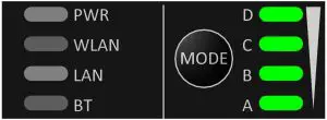
| RSSI (WLAN Client) / Link Quality (Bluetooth PANU) | ||||
| LED | Description | |||
| No connection | ||||
| A | RSSI/Link Quality < 25 % | |||
| A | B | RSSI/Link Quality 25–50 % | ||
| A | B | C | RSSI/Link Quality 50–75 % | |
| A | B | C | D | RSSI/Link Quality > 75 % |
These LEDs are also used when selecting an Easy Config mode and to indicateupdate status in Recovery Mode.
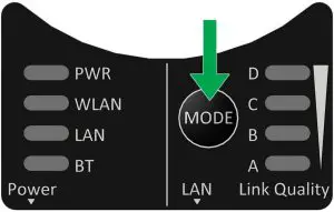
The MODE button can be used to restart or reset the unit as well as for selecting an Easy Config mode.
When the unit is powered on, press and hold MODE for >10 seconds and then release it to reset to the factory default settings.
Recovery Mode
If the web interface cannot be accessed, the unit can be reset by starting in Recovery Mode and reinstalling the firmware using Anybus Firmware Manager II, which can be downloaded from www.anybus.com/support.
To enter Recovery Mode, press and hold RESET during startup.
![]() Firmware updates should normally be carried out through the web interface. Recovery Mode should only be used if the unit is unresponsive and the web interface cannot be accessed.
Firmware updates should normally be carried out through the web interface. Recovery Mode should only be used if the unit is unresponsive and the web interface cannot be accessed.
Recovery Mode LED Indications
In Recovery Mode the Status LEDs will indicate firmware update status:
| PWR | Green | Firmware update in progress |
| Green, blinking | Waiting for valid firmware | |
| WLAN + BT | Alternating red/blue | Firmware update in progress |
Configuration
Anybus Wireless Bridge II is normally configured via the web interface or using one of the pre-configured Easy Config modes.
Advanced configuration can be carried out by issuing AT commands via the web interface or over a Telnet or RAW TCP connection to port 8080.
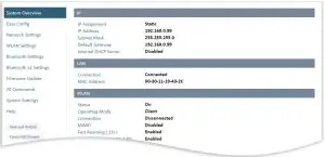
Web Interface
The web interface is accessed by pointing a web browser to the IP address ofthe unit. The default address is 192.168.0.99
The configuration settings are described in detail in the User Manual.
Easy Config
- Power on the unit and wait for the Link Quality LEDs to light up and go out again, then immediately press and release the MODE button.
- Press MODE repeatedly to cycle through the Easy Config modes until the desired mode is indicated by the A-B-C-D LEDs.
- Within 20 seconds of step 2, press and hold MODE for 2 seconds. When the button is released the unit will restart in the selected mode.
Easy Config Modes
| EC | LED | Role | Description | |||
| 1 | A | Bluetooth PANU | Configure as a client and scan for another client (PANU to PANU). | |||
| 2 | B | – | Reset configuration to factory defaults. | |||
| 3 | A | B | – | Reset IP settings to factory defaults. | ||
| 4 | C | Client | Wait for automatic configuration. | |||
| 5 | A | C | WLAN AP | Configure units in mode 4 as clients.
Restart as access point and connect clients. |
||
| 6 | B | C | Bluetooth NAP | |||
| 7 | A | B | C | WLAN AP | Configure units in mode 4 as clients. Restart as access point and connect clients.Apply PROFINET optimization to all units. | |
| 8 | D | Bluetooth NAP | ||||
| 9 | A | D | Bluetooth PANU | Configure as a client and scan for another client (PANU to PANU). Apply PROFINET optimization to both units. | ||
| 10 | B | D | (any) | Apply PROFINET optimization and restart. | ||
| 11 | A | B | D | (any) | Enable PROFIsafe mode. |
The Easy Config modes are also described when selected in the web interface.
I/O-Data Cycle Time
Based on recommendations from industrial equipment suppliers, such as Rockwell and Siemens, it is recommended to use the following minimum I/Odata cycle times for PROFINET and EtherNet/IP networks:
- Wireless link Point-to-Point with Bluetooth PANU-PANU or Wi-Fi Access Point to Station: 32 ms
- Wireless link with Access Point and up to 4 wireless clients/stations, Bluetooth or Wi-Fi: 64 ms
Factory Restore
Any one of these actions will restore the factory default settings:
- Clicking on Factory Restore on the System Settings page
- Executing Easy Config Mode 2
- Issuing the AT command AT&F and then restarting the unit
- Holding MODE pressed for >10 seconds and then releasing it
- Applying voltage to the digital input for >10 seconds
|
Default Network Settings |
|
|
IP Assignment |
Static |
| IP Address |
192.168.0.99 |
|
Subnet Mask |
255.255.255.0 |
| Default Gateway |
192.168.0.99 |
|
Internal DHCP Server |
Disabled |
| DHCP Interfaces |
All |
|
Default WLAN Settings |
|
|
Operating Mode |
Client |
| Channel Bands |
2.4 GHz & 5 GHz |
|
Authentication Mode |
WPA/WPA2–PSK |
| Channel |
Auto |
|
Bridge Mode |
Layer 3 IP forward |
| MIMO |
AWB3000: Enabled AWB3010: Disabled |
|
Default Bluetooth Settings |
|
|
Operating Mode |
PANU (Client) |
| Local Name |
[generated from MAC address] |
|
Connectable |
No |
| Discoverable |
No |
|
Security Mode |
Just works |
| Bluetooth LE |
Operating Mode: Disabled Connectable: NoDiscoverable: No |
Technical Data
Hardware Specifications
|
Order code |
AWB3000 | AWB3010 |
| Wired Interface type |
Ethernet |
|
|
Antenna |
3 internal antennas:2.4 GHz2.4 GHz MIMO 5 GHz | 1 external antenna:2.4 GHz + 5 GHz dual band |
| Dimensions (LxWxH) |
93 x 68 x 33.2 mm |
|
|
Weight |
120 g | |
| Operating temperature |
-40 to +65 °C |
|
|
Storage temperature |
-40 to +85 °C | |
| Humidity |
EN 600068-2-78: Damp heat, +40 °C, 93 % humidity for 4 days |
|
|
Vibration |
See datasheet | |
| Housing material |
Plastic (see datasheet for details) |
|
|
Protection class |
IP65 | |
| Mounting |
Screw mount or DIN rail using optional clip |
|
|
Power connector |
M12 male A-coded | |
| Ethernet connector |
M12 female D-coded |
|
|
Power supply |
9–30 VDC (-5 % +20 %) Cranking 12 V (ISO 7637-2:2011 pulse 4) Reverse polarity protection | |
| Power consumption |
0.7 W (idle), 1.7 W (max) |
Installation Drawing
report this adAll measurements are in mm.
References
[xyz-ips snippet=”download-snippet”]