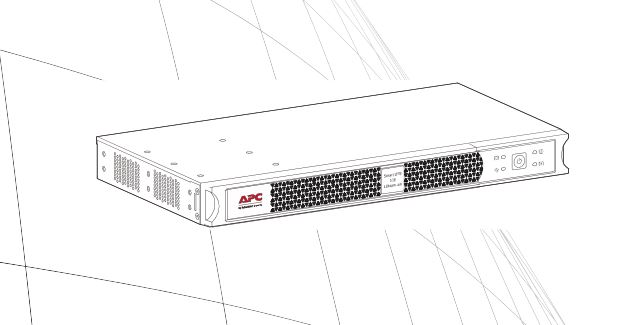
APC Smart-UPS Owner's Manual
This manual provides critical product, safety and installation information for the SCL500RM1UC and SCL500RM1UNC. The only difference between these two models is in their monitoring and management options. The SCL500RM1UC has the “SmartConnect” port, which allows the product to be monitored remotely. Learn more about the APCTM SmartConnect feature on www.smartconnect.apc.com. The SCL500RM1UNC can be managed via traditional methods and APC softwares, it has an embedded network management card, the AP9537SUM.
Important Safety Messages
SAVE THESE INSTRUCTIONS – This manual contains important instructions that should be followed during installation and maintenance of the UPS and batteries.
Read these instructions carefully and look at the equipment to become familiar with the device before trying to install, operate, service or maintain it. The following special messages may appear throughout this bulletin or on the equipment to warn of potential hazards or to call attention to information that clarifies or simplifies a procedure.
![]() The addition of this symbol to either a “Danger” or “Warning” safety label indicates that an electrical hazard exists which will result in personal injury if the instructions are not followed.
The addition of this symbol to either a “Danger” or “Warning” safety label indicates that an electrical hazard exists which will result in personal injury if the instructions are not followed.
![]() This is the safety alert symbol. It is used to alert you to potential personal injury hazards. Obey all safety messages that follow this symbol to avoid possible injury or death.
This is the safety alert symbol. It is used to alert you to potential personal injury hazards. Obey all safety messages that follow this symbol to avoid possible injury or death.

Product Handling Guidelines

Safety and General Information
Inspect the package contents upon receipt. Notify the carrier and dealer if there is any damage.
General safety
- Adhere to all national and local electrical codes.
- All wiring must be performed by a qualified electrician.
- Changes and modifications to this unit not expressly approved by APC by Schneider Electric could void the warranty.
- This UPS is intended for indoor use only.
- Do not operate this unit in direct sunlight, in contact with fluids, or where there is excessive dust or humidity.
- Be sure the air vents on the UPS are not blocked. Allow adequate space for proper ventilation.
- For a UPS with a factory installed power cord, connect the UPS power cable directly to a wall outlet. Do not use surge protectors or extension cords.
- The equipment is heavy. Always practice safe lifting techniques adequate for the weight of the equipment.
Deenergizing safety
The UPS contains internal batteries and may present a shock hazard even when disconnected from the branch circuit (mains). Before installing or servicing the equipment check that the:
- Input circuit breaker is in the OFF position.
- Internal UPS batteries are removed.
Electrical safety
- Use tools with insulated handles.
- Do not handle any metallic connector before power has been disconnected.
- For models with a hardwired input, the connection to the branch circuit (mains) must be performed by a qualified electrician.
- 230 V models only: In order to maintain compliance with the EMC directive for products sold in Europe, output cords attached to the UPS must not exceed 10 meters in length.
- The protective earth conductor for the UPS carries the leakage current from the load devices (computer equipment). An insulated ground conductor is to be installed as part of the branch circuit that supplies the UPS. The conductor must have the same size and insulation material as the grounded and ungrounded branch circuit supply conductors. The conductor will typically be green, with or without a yellow stripe.
- Leakage current for a pluggable, Type A UPS may exceed 3.5 mA when a separate ground terminal is used.
- The UPS input ground conductor must be properly bonded to protective earth at the service panel.
- If the UPS input power is supplied by a separately derived system, the ground conductor must be properly bonded at the supply transformer or motor generator set.
Battery safety
![]() WARNINGRISK OF CHEMICAL HAZARD AND EXCESSIVE HEAT
WARNINGRISK OF CHEMICAL HAZARD AND EXCESSIVE HEAT
- Recycle the UPS when the UPS battery error is detected at the end of its service life. Power off the UPS and unplug it from the AC input.
- The battery is not user replaceable. Contact APC by Schneider Electric Worldwide Customer Support if there are defects in the product and the product is within warranty.
Failure to follow these instructions can result in death or serious injury.
- The batteries typically last for 10 years and operate between 0 and 40 °C. Environmental factors impact battery life. Elevated ambient temperatures, poor quality utility power, and frequent short duration discharges will shorten battery life. Batteries should be replaced before end of life. Due to the long life of the batteries, we recommend replacing the unit entirely. For longest battery performance, the ambient temperature should be maintained between 68° and 77°F (20° and 25°C).
- This unit uses Lithium Ion (LFP) batteries. Under normal use and handling, there is no contact with the internal components of the battery.
- Servicing of user replaceable batteries should to be performed or supervised by personnel knowledgeable about batteries and required precautions. In this case, batteries are not user replaceable.
- Disconnect the charging source prior to connecting or disconnecting battery terminals.
- CAUTION: Before installing or replacing the batteries, remove conductive jewelry such as chains, wrist watches and rings. High energy through conductive materials could cause severe burns.
- CAUTION: Do not dispose of batteries in a fire. The batteries may explode.
- CAUTION: Do not open the plastic case of the batteries. Doing so will expose the cell terminals which pose an energy hazard.
- CAUTION: Do not open or mutilate the battery or batteries. Released electrolyte is harmful to the skin and eyes. It may be toxic.
- CAUTION: Failed batteries can reach temperatures that exceed the burn thresholds for touchable surfaces·
General information
- The model and serial numbers are located on a small, rear panel label. For some models, an additional label is located on the chassis under the front bezel.
- Always recycle used batteries.
- Recycle the package materials or save them for reuse.
FCC Class A radio frequency warning
This equipment has been tested and found to comply with the limits for a Class A digital device, pursuant to part 15 of the FCC Rules. These limits are intended to provide reasonable protection against harmful interference when the equipment is operated in a commercial environment. This equipment generates, uses, and can radiate radio frequency energy and, if not installed and used in accordance with the instruction manual, may cause harmful interference to radio communications. Operation of this equipment in a residential area is likely to cause harmful interference in which case the user will be required to correct the interference at his own expense.
SCL500RM1UC and SCL500RM1UNC Rack-Mount

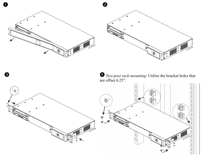
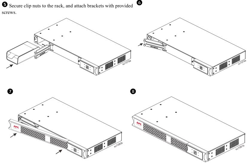
Rack-Mounting
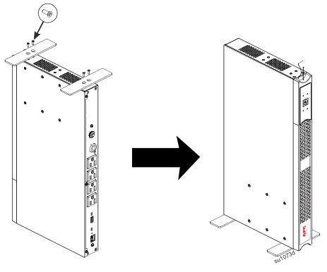
 Tower Configuration
 Tower Configuration
Attention: Connect the battery before tower setup by referring to applicable steps in “Rack-Mounting” .
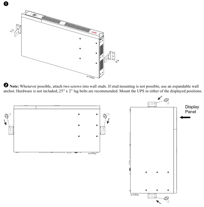
Wall Mounting
 Wall Mounting
Attention: Connect the battery before mounting by referring to applicable steps in “Rack-Mounting” . To avoid a safety hazard, do not mount the unit on the wall with the bezel facing downwards, or with the display panel at the bottom.
Specifications
 Specifications
For additional specifications, refer to the APC Web site at www.apc.com.
Environmental specifications
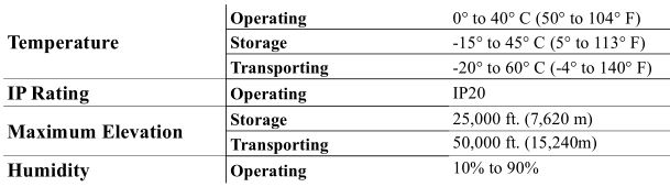 Note: The recommended recharge interval for this UPS is 12 months. The transporting conditions are for 2 weeks maximum.
Product Overview
SCL500RM1UC & SCL500RM1UNC Rack-Mount
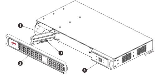
- Battery
- Bezel
- Battery Door
- Display (more information below)
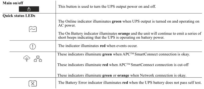
Front panel display features
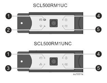
- Online / On Battery indicator
- APC ™ SmartConnect status indicator
- Network status indicator
- Event Detected indicator
- Battery Error indicator
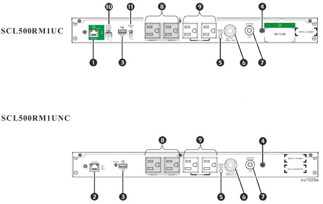
Rear panel features
- APC ™ SmartConnect port
- Network port
- USB port
- Chassis ground connection screw
- Building Wiring Fault indicator
- UPS input power cord
- Circuit breaker
- Controlled outlet group
- Outlets
- APC ™ SmartConnect Control
- Modbus TCP Control
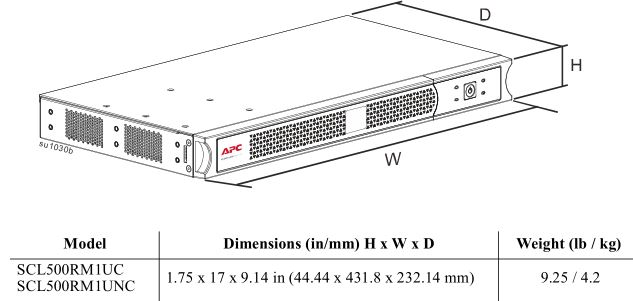
Dimensions and weights
 Dimensions and weights
SCL500RM1UC and SCL500RM1UNC Rack-Mount Models
Installation
For UPS installation information, refer to the Installation Guide included with the UPS.
Placement
The UPS is intended for IT environments. Avoid placement where there is excessive dust and humidity. Note that temperature in excess of 25o C may have an adverse effect on battery and UPS life. All vents on the side or rear of the UPS should be free of obstructions. The UPS is heavy. The UPS should be placed near the bottom of the rack.
Connect to equipment and utilities
Note: The UPS will charge to 90% capacity in the first three hours of normal operation. Do not expect full battery runtime capability during this initial charge period.
![]() CAUTIONRISK OF INJURY OR DAMAGE TO EQUIPMENT
CAUTIONRISK OF INJURY OR DAMAGE TO EQUIPMENT
- Adhere to all local and national electrical codes.
- Wiring should be performed by qualified electrician.
- Always connect the UPS to a grounded outlet.
Failure to follow these instructions can result in injury or equipment damage.
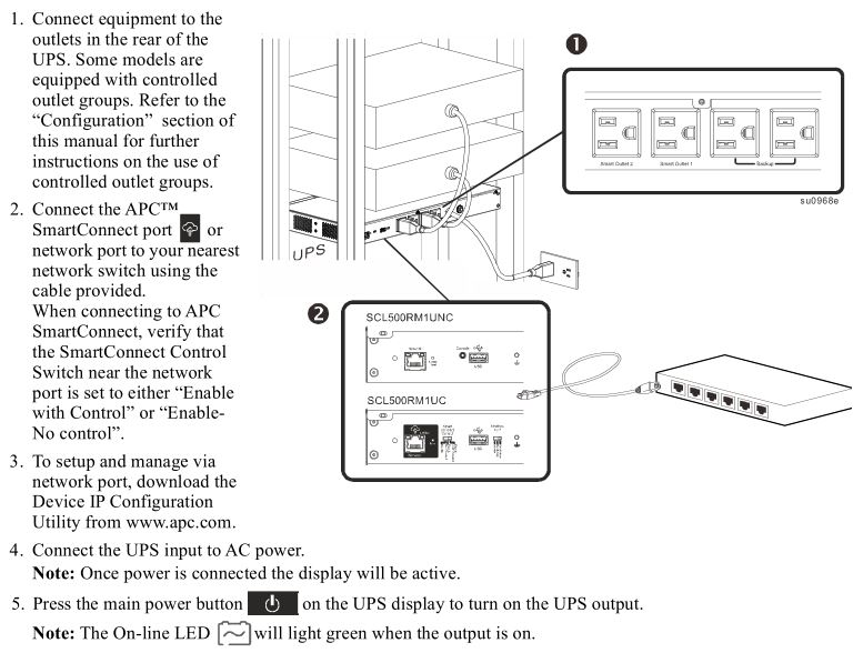
Note: The On-line LED will light green when the output is on.
APCTM SmartConnect
APCTM SmartConnect allows you to monitor the health and status of your UPS from any device connected to the Internet. Visit www.smartconnect.apc.com to learn more. Log onto www.smartconnect.apc.com or scan the QR code to launch the registration process. The website includes instructions to setup your online account, activate your warranty and begin monitoring your UPS remotely. By connecting this product to the Internet using the APCTM SmartConnect port, you are agreeing to APCTM SmartConnect Terms of Use, as found at smartconnect.apc.com. Schneider Electric Data Privacy Policy can also be found at smartconnect.apc.com.
Device IP configuration utility
The Device IP Configuration Utility can discover Network Management Cards (NMC 2) that do not have an IP address assigned. Once discovered, you can configure the IP address settings for the cards. You can also search for devices already on the network by entering an IP range to define the search. The Utility scans the IP addresses in the defined range and discovers cards that already have a DHCP-assigned IP address. For detailed information on the Utility, see the Knowledge Base on the support page of the www.apc.com website and search for FA156064 (the ID of the relevant article). Once IP address found, access the Web management interface by this IP address. Enter the user name and password to login (by default, use apc and apc to login as the administrator).
Connect and install management software
Smart-UPS is provided with PowerChute management software for unattended operating system shutdown, UPS monitoring, UPS control and energy reporting. The following diagram is a representation of a typical server installation.
1. Connect the USB cable (SCL500RM1UC) / Network cable (SCL500RM1UNC) from the rear of the UPS / Network Port to the protected device such as a server.
2. For a server or other device with an operating system, load the PowerChute CD and follow the on-screen set-up instructions. PowerChute provides for graceful shutdown in the event of an extended power outage and is a powerful management interface on the local network.
Operation
 Operation
Using the display
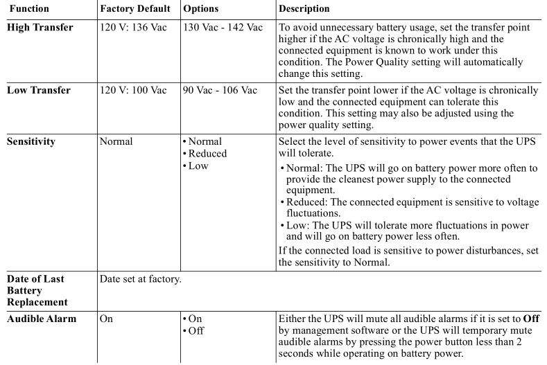
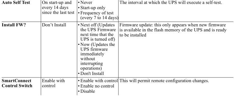
Configuration
 Configuration
General configuration settingsConfiguration settings may be changed at any time using the PowerChute software or SmartConnect Switch. This table provides a brief description of the general settings, for more detailed information on each of these parameters consult application note 80 at www.apc.com.
Outlet group configuration settings
The Main Outlet Group and the Controlled Outlet Group can be configured to independently turn off, turn on, shutdown, or reboot connected equipment.
- Turn off: Disconnect from power immediately and connect only with a manual command.
- Turn on: Connect to power immediately.
- Shutdown: Disconnect from power and automatically connect when AC power becomes available.
- Reboot: Disconnect from power, wait for a specified amount of time, then connect to power.
In addition, the Main Outlet Group and the Controlled Outlet Group can be configured to do the following:
- Turn on or off in a specified sequence
- Automatically turn off or shut down when various conditions occur
Note: If the Main and Controlled Outlet Groups are not configured, all of the outlets on the unit will still providebattery back-up power.
Note: The Main Outlet Group must be turned on for the Controlled Outlet Group to turn on.
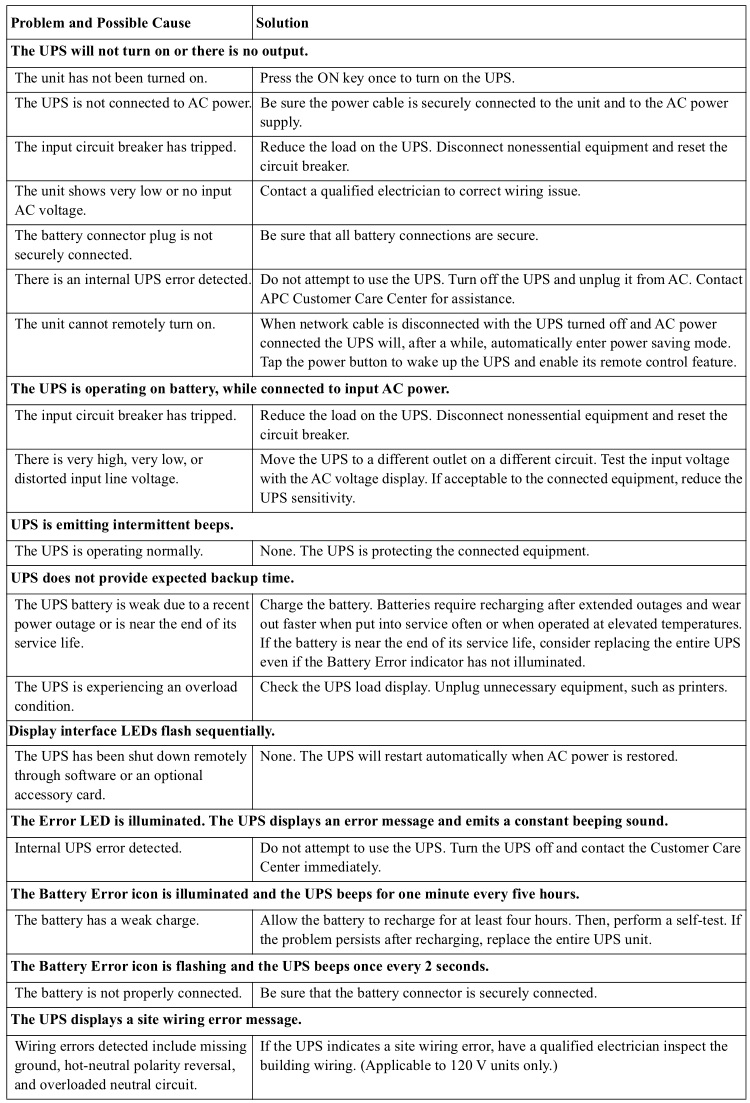
Troubleshooting
Limited Factory Warranty
Schneider Electric IT Corporation (SEIT), warrants its products to be free from defects in materials and workmanship for a period of five(5) years from the date of purchase. The SEIT obligation under this warranty is limited to repairing or replacing, at its own sole option, any such defective products. Repair or replacement of a defective product or parts thereof does not extend the original warranty period.
This warranty applies only to the original purchaser who must have properly registered the product within 10 days of purchase. Products may be registered online at warranty.apc.com.
SEIT shall not be liable under the warranty if its testing and examination disclose that the alleged defect in the product does not exist or was caused by end user’s or any third person’s misuse, negligence, improper installation, testing, operation or use of the product contrary to SEIT’s recommendations or specifications. Further, SEIT shall not be liable for defects resulting from: 1) unauthorized attempts to repair or modify the product, 2) incorrect or inadequate electrical voltage or connection, 3) inappropriate on site operation conditions, 4) Acts of God, 5) exposure to the elements, or 6) theft. In no event shall SEIT have any liability under this warranty for any product where the serial number has been altered, defaced, or removed.
EXCEPT AS SET FORTH ABOVE, THERE ARE NO WARRANTIES, EXPRESS OR IMPLIED, BY OPERATION OF LAW OR OTHERWISE, APPLICABLE TO PRODUCTS SOLD, SERVICED OR FURNISHED UNDER THIS AGREEMENT OR IN CONNECTION HEREWITH.
SEIT DISCLAIMS ALL IMPLIED WARRANTIES OF MERCHANTABILITY, SATISFACTION AND FITNESS FOR A PARTICULAR PURPOSE.
SEIT EXPRESS WARRANTIES WILL NOT BE ENLARGED, DIMINISHED, OR AFFECTED BY AND NO OBLIGATION OR LIABILITY WILL ARISE OUT OF, SEIT’S RENDERING OF TECHNICAL OR OTHER ADVICE OR SERVICE IN CONNECTION WITH THE PRODUCTS.
THE FOREGOING WARRANTIES AND REMEDIES ARE EXCLUSIVE AND IN LIEU OF ALL OTHER WARRANTIES AND REMEDIES. THE WARRANTIES SET FORTH ABOVE CONSTITUTE SEIT’S SOLE LIABILITY AND PURCHASER’S EXCLUSIVE REMEDY FOR ANY BREACH OF SUCH WARRANTIES. SEIT WARRANTIES EXTEND ONLY TO ORIGINAL PURCHASER AND ARE NOT EXTENDED TO ANY THIRD PARTIES.
IN NO EVENT SHALL SEIT, ITS OFFICERS, DIRECTORS, AFFILIATES OR EMPLOYEES BE LIABLE FOR ANY FORM OF INDIRECT, SPECIAL, CONSEQUENTIAL OR PUNITIVE DAMAGES, ARISING OUT OF THE USE, SERVICE OR INSTALLATION OF THE PRODUCTS, WHETHER SUCH DAMAGES ARISE IN CONTRACT OR TORT, IRRESPECTIVE OF FAULT, NEGLIGENCE OR STRICT LIABILITY OR WHETHER SEIT HAS BEEN ADVISED IN ADVANCE OF THE POSSIBILITY OF SUCH DAMAGES. SPECIFICALLY, SEIT IS NOT LIABLE FOR ANY COSTS, SUCH AS LOST PROFITS OR REVENUE, WHETHER DIRECT OR INDIRECT, LOSS OF EQUIPMENT, LOSS OF USE OF EQUIPMENT, LOSS OF SOFTWARE, LOSS OF DATA, COSTS OF SUBSTITUANTS, CLAIMS BY THIRD PARTIES, OR OTHERWISE.
NOTHING IN THIS LIMITED WARRANTY SHALL SEEK TO EXCLUDE OR LIMIT SEIT’S LIABILITY FOR DEATH OR PERSONAL INJURY RESULTING FROM ITS NEGLIGENCE OR ITS FRAUDULENT MISREPRESENTATION OF TO THE EXTENT THAT IT CANNOT BE EXCLUDED OR LIMITED BY APPLICABLE LAW.
To obtain service under warranty you must obtain a Returned Material Authorization (RMA) number from customer support. Customers with warranty claims issues may access the SEIT worldwide customer support network through the SEIT Web site: www.apc.com. Select your country from the country selection drop down menu. Open the Support tab at the top of the web page to obtain information for customer support in your region. Products must be returned with transportation charges prepaid and must be accompanied by a brief description of the problem encountered and proof of date and place of purchase.
Transport the Unit
1. Shut down and disconnect all equipment.2. Disconnect the unit from utility power.3. Disconnect all internal and external batteries (if applicable).4. Follow the shipping instructions outlined in the Service section of this manual.
Service
If the unit requires service, do not return it to the dealer. Follow these steps:
- Review the Troubleshooting section of the manual to eliminate common problems.
- If the problem persists, contact APC Customer Support through the APC web site, www.apc.com.
- a. Note the model number and serial number and the date of purchase. The model and serial numbers are located on the rear panel of the unit and are available through the LCD interface on select models.
- b. Call APC Support and a technician will attempt to solve the problem over the phone. If this is not possible, the technician will issue a Returned Material Authorization Number (RMA#).
- c. If the unit is under warranty, it will be repaired or replaced at no cost.
- d. Service procedures and returns may vary internationally. Refer to the APC web site for country specific instructions.
- Pack the unit properly to avoid damage in transit. Never use foam beads for packaging. Damage sustained in transit is not covered under warranty.
- Before shipping, always disconnect all battery modules in a UPS or external battery pack.
- Write the RMA# provided by Customer Support on the outside of the package.
- Return the unit by insured, prepaid carrier to the address provided by Customer Support.
APC by Schneider Electric Worldwide Customer Support
Customer support for this or any other APC by Schneider Electric product is available at no charge in any of the following ways:
- Visit the APC by Schneider Electric web site to access documents in the APC by Schneider Electric Knowledge Base and to submit customer support requests.
- www.apc.com (Corporate Headquarters)Connect to localized APC by Schneider Electric web sites for specific countries, each of which provides customer support information.
- www.apc.com/support/Global support searching APC by Schneider Electric Knowledge Base and using e-support.
- Contact the APC by Schneider Electric Customer Support Center by telephone or e-mail.
- Local, country specific centers: go to www.apc.com/support/contact for contact information.
- For information on how to obtain local customer support, contact the APC by Schneider Electric representative or other distributor from whom you purchased your APC by Schneider Electric product.
![]() Select models are compliant with California (CEC) Battery Charger regulations. For more information on your specific model go to www.apc.com.
Select models are compliant with California (CEC) Battery Charger regulations. For more information on your specific model go to www.apc.com.
© 05/2020 APC by Schneider Electric. APC, the APC logo, Smart-UPS, SmartConnect and PowerChute are owned by Schneider Electric Industries S.A.S. or their affiliated companies. All other trademarks are property of their respective owners.
EN 990-91144A
05/2020
References
[xyz-ips snippet=”download-snippet”]