![]() User Manual Smart-UPS™ Modular1500/3000 VA 120/230 Vac Rack-Mount 2U
User Manual Smart-UPS™ Modular1500/3000 VA 120/230 Vac Rack-Mount 2U
Important Safety Messages
SAVE THESE INSTRUCTIONS – This manual contains important instructions that should be followed during the installation and maintenance of the Smart-UPS and batteries.Read these instructions carefully and look at the equipment to become familiar with the device before trying to install, operate, service, or maintain it. The following special messages may appear throughout this bulletin or on the equipment to warn of potential hazards or to call attention to information that clarifies or simplifies a procedure.
![]() The addition of this symbol either to a “Danger” or “Warning” safety label indicates that an electrical the hazard exists which will result in personal injury if the instructions are not followed.
The addition of this symbol either to a “Danger” or “Warning” safety label indicates that an electrical the hazard exists which will result in personal injury if the instructions are not followed.
![]() This is the safety alert symbol. It is used to alert you to potential personal injury hazards. Obey all safety messages that follow this symbol to avoid possible injury or death.
This is the safety alert symbol. It is used to alert you to potential personal injury hazards. Obey all safety messages that follow this symbol to avoid possible injury or death.
|
|
| DANGER indicates a hazardous situation that, if not avoided, will result in death or serious injury. |
|
|
| WARNING indicates a hazardous situation that, if not avoided, could result in death or serious injury. |
|
|
| CAUTION indicates a hazardous situation that, if not avoided, could result in minor or moderate injury. |
|
NOTICE |
| NOTICE is used to address practices not related to physical injury. |
Product Handling Guidelines

Safety and General Information
- Adhere to all national and local electrical codes.
- All wiring must be performed by a qualified electrician.
- Changes and modifications to this unit not expressly approved by APC could void the warranty.
For Professional Business Applications – Not For Consumer Use
- This unit is intended for indoor use only.
- This unit is capable of operating in temperatures of 0 °C to 40 °C and Humidity up to 95% RH.
- Do not operate this unit in direct sunlight, in contact with fluids, or where there is excessive dust or humidity.
- Be sure the air vents on this unit are not blocked. Allow adequate space for proper ventilation.
- For a UPS with a factory-installed power cord, connect the UPS power cable directly to a wall outlet. Do not use surge protectors or extension cords.
- The UPS will recognize as many as 10 external battery packs connected to the UPS.Note: For each XLBP that is added, increased recharge time will be required.
- The equipment is heavy. Always practice safe lifting techniques adequate for the weight of the equipment.
- The batteries are heavy. Remove the batteries before installing the UPS and external battery packs (XLBPs), in a rack.
- Always install XLBPs at the bottom in rack-mount configurations. The UPS must be installed above the XLBPs.
- Always install peripheral equipment above the UPS in rack-mount configurations.
- Additional safety information can be found in the Safety Guide supplied with this unit.
Deenergizing safety
- The UPS contains internal batteries and may present a shock hazard even when disconnected from AC and DC power.
- The AC and DC output connectors may be energized by remote or automatic control at any time.
- Before installing or servicing the equipment check the:– Mains circuit breaker is in the OFF position– Internal UPS batteries are removed– XLBP battery modules are disconnected
Electrical safety
- For models with a hardwired input, the connection to the branch circuit (mains) must be performed by aqualified electrician.
- 230 V models only: In order to maintain compliance with the EMC directive for products sold in Europe, output cords attached to the UPS must not exceed 10 meters in length.
- The protective earth conductor for the UPS carries the leakage current from the load devices (computerequipment). An insulated ground conductor is to be installed as part of the branch circuit that supplies the UPS.The conductor must have the same size and insulation material as the grounded and ungrounded branch circuit supply conductors. The conductor will typically be green and with or without a yellow stripe.
- The UPS input ground conductor must be properly bonded to protective earth at the service panel.
- If the UPS input power is supplied by a separately derived system, the ground conductor must be properlybonded at the supply transformer or motor-generator set.
Battery safety
- It is not necessary to ground the battery system. The user has the option of referencing the battery system to chassis ground at either a positive or negative battery terminal.
- Replace batteries with the same number and type of batteries as originally installed in the equipment.
- The battery typically lasts for two to five years. Environmental factors impact battery life. Elevated ambient temperatures, poor quality utility power, and frequent short-duration discharges will shorten battery life.
- Replace batteries immediately when the unit indicates battery replacement is necessary.
- Schneider Electric uses Maintenance-Free sealed Lead Acid batteries. Under normal use and handling, there is no contact with the internal components of the battery. Overcharging, overheating or another misuse of batteries can result in a discharge of battery electrolyte. Released electrolyte is toxic and may be harmful to the skin and eyes.
- CAUTION: Before installing or replacing the batteries, remove jewelry such as wristwatches and rings.High short circuit current through conductive materials could cause severe burns.
- CAUTION: Do not dispose of batteries in a fire. The batteries may explode.
- CAUTION: Do not open or mutilate batteries. Released material is harmful to the skin and eyes and may be toxic.
General information
- The UPS will recognize as many as 10 external battery packs connected to the UPS.Note: For each XLBP added, increased recharge time will be required.
- The model and serial numbers are located on a small, rear panel label. For some models, an additional label is located on the chassis under the front bezel.
- Always recycle used batteries.
- Recycle the packing materials or save them for reuse.
Product Overview
The APC™ by Schneider Electric Smart-UPS™ is a high-performance uninterruptible power supply (UPS). The UPS provides protection for electronic equipment from utility power blackouts, brownouts, sags, surges, small utility power fluctuations, and large disturbances. The UPS also provides battery backup power for connected equipment until utility power returns to safe levels or the batteries are fully discharged.This user manual is available on the enclosed CD and on the APC by Schneider Electric Web site, www.apc.com.
Package Contents
Note: Read the safety instruction sheet before installation.Inspect the UPS upon receipt. Notify the carrier and dealer if there is damage.The packaging is recyclable; save it for reuse or dispose of it properly.Check the package contents:
- UPS
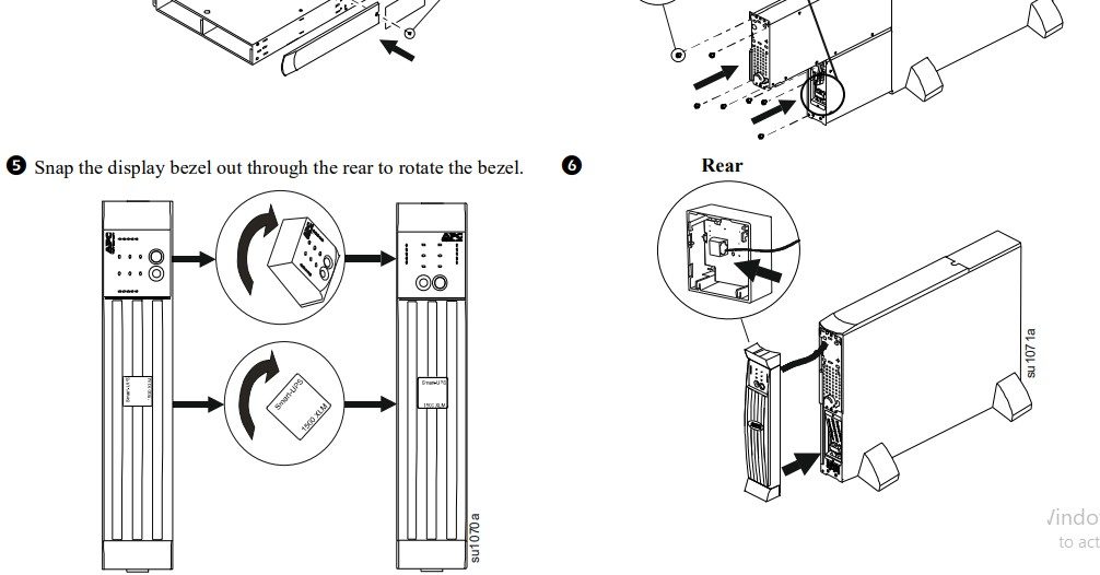
- Bezel
- Tower conversion top panels and mounting stabilizers
- Rail kit
- UPS literature kit containing:
- Product documentation, safety, and warranty information
- Documentation CD
- PowerChute™ CD
- Network Management Card CD
- Mounting hardware
- Serial and USB communication cables
- 230 V models only:Two input power cordsTwo output jumper cords
Mount the UPS in the Rack and Connect the Battery
|
|
RISK OF FALLING EQUIPMENT
|
Tower Configuration
|
|
RISK OF FALLING EQUIPMENT
|
Start-Up
Connect Equipment to the UPS
| CAUTION |
RISK OF ELECTRIC SHOCK
|
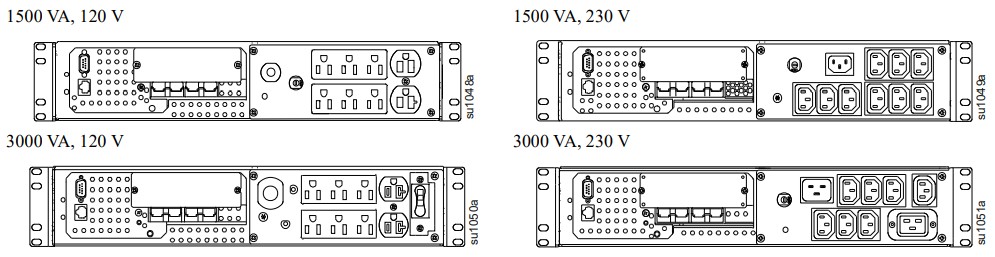
Rear Panels
Note:
- The ‘outlet groups’ can be controlled through the network software. See Network Management Carddocumentation.
- A laser printer draws significantly more power than other types of equipment and may overload the UPS.
Connect the UPS to the Network (if Applicable)Network Connectors
| Serial Port | |
| USB Port |  |
| Ethernet Port | |
Note:
- Use only the supplied cable to connect to the Serial Port. A standard serial interface cable is incompatible with the UPS.Note: Serial and USB ports cannot be used simultaneously.
- If an optional SmartSlot accessory is to be used, remove the preinstalled network management card and install it now.
Start the UPSNote: The UPS will automatically turn on when utility power is connected.
- Plug the UPS into a two-pole, three-wire, grounded receptacle only.– Input Plugs:• 1500 VA models: 120 V = NEMA 5-15P; 230 V = Use country-specific 10 A with C14 input cords (notsupplied).• 3000 VA models: 120 V = NEMA L5-30P; 230 V = Use the supplied cords or the country-specific equivalent.– The battery will charge to full capacity during the first few hours of normal operation. Do not expect full ‘on battery’ capability during this initial charge period.
- After the UPS has ended the immediate self-test with Online LED illumination, check the front display for any fault indicators. See “Troubleshooting” on page 11 for details.
- 120 V models: Check the Site wiring fault LED located on the rear panel. It will be illuminated if the UPS is plugged into an improperly wired utility power outlet. See “Troubleshooting” on page 11 for details.
- Turn on all connected equipment. To use the UPS as a master on/off switch, be sure all connected equipment is on.Equipment is now powered and protected. Basic operation, user configuration, and software utilization can now be performed as required.
Battery OperationThe UPS switches to battery operation automatically if the utility power fails. While running on battery, an alarm beeps four times every 30 seconds. Press the POWER ON button to silence this alarm.If the utility power does not return, the UPS continues to supply power to the connected equipment until the battery is fully discharged.
- Refer to www.apc.com for battery runtime charts.
- When the UPS reaches the low battery shutdown alert (two-minute default), the audible alarm will beepcontinuously until the total shutdown. Connected equipment should be shut down during this time unless being controlled by network monitoring software.
Basic Operation
|
Indicator |
Description |
| Online |
The UPS is supplying utility power to the connected equipment. |
| AVR |
The UPS is compensating for either a high or low utility voltage. |
| Battery |
The UPS is supplying battery power to the connected equipment. |
| Overload |
The connected loads are drawing more than the UPS power rating. |
| Bypass |
The connected loads are being powered directly by the utility power connection and not through the power processing module. This condition may be caused either due to an overload or an internal fault in the UPS.See “Troubleshooting” on page 11 for details. |
| Replace Battery/ Battery Disconnected |
The battery is disconnected or must be replaced. |
|
Feature |
Function |
| Power On |
Press this button to turn on the UPS |
| Power Off |
Press this button to turn off the UPS. |
| Self-Test | Automatic: The UPS performs a self-test automatically when turned on, and every two weeks thereafter (by default). During the self-test, the UPS briefly operates the connected equipment on the battery.Manual: Press and hold the POWER ON button for a few seconds to initiate the self-test. |
| Cold Start | Supply battery power to the UPS and connected equipment in the absence of utility voltage. See “Troubleshooting” on page 11 for details. Press the POWER ON button for one second and release. The UPS will beep briefly and go quiet. Press and hold the button again, but for approximately three seconds.The unit will emit a sustained beep. Release the button during this beep. |
Diagnostic Utility Voltage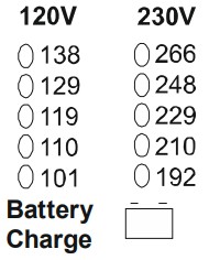 |
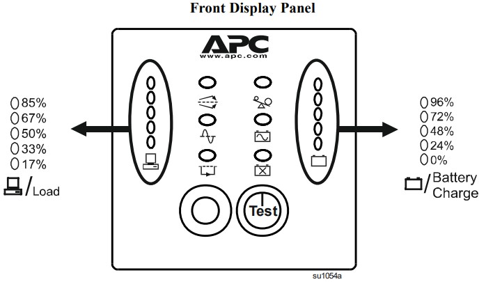
The UPS has a diagnostic feature that displays the utility voltage.The UPS starts a self-test as part of this procedure. The self-test does not affect the voltage display. Press and hold the POWER ON button to view the utility voltage bar graph display. After a few seconds, this five LED Battery charge display on the right of the front panel will show the utility input voltage.Refer to the figure at left for the voltage reading (values are not listed on the UPS).The display indicates the voltage is between the displayed value on the list and the next higher value. See “Troubleshooting” on page 11 for details. |
User Configurable Items
Note: Settings are made through the supplied PowerChute software or the network interface connection. Refer to the software help guides for details.
| Function | Factory Default | User Selectable Choices | Description |
| Automatic Self-Test | Every 14 days (336 hours) | Every 14 days (336 hours), Every 7 days (168 hours), On Startup Only, No Self-Test |
This function sets the interval at which the UPS will execute a self-test. |
| UPS ID | UPS_IDEN | Up to eight characters |
Use this field to uniquely identify the UPS, (i.e., server name or location) for network management purposes. |
| Date of Last Battery Replacement | Manufacture Date | mm/dd/yy |
Reset this date when you replace the internal battery module. |
| Minimum Capacity Before Return from Shutdown | 0 percent | 0, 15, 30, 45, 60, 75,
90 percent |
The UPS will charge its batteries to the specified percentage before powering up connected equipment, following a low battery shutdown. |
| Voltage Sensitivity | High | High, Medium, Low |
The UPS detects and reacts to line voltage distortions by transferring to battery power to protect the connected equipment. When power quality is poor, the UPS may frequently transfer to battery power. If the connected equipment can operate normally under such line voltage conditions, reduce the sensitivity setting to conserve the battery’s capacity and service life. |
| Alarm Control | Enable | Enable, Mute, Disable |
Users can mute an ongoing audible alarm or disable all existing audible alarms permanently. |
| Shutdown Delay | 90 seconds | 90, 180, 270, 360, 450, 540, 630, 0 seconds |
The interval is set between the times when the UPS receives a shutdown command and when it shuts off power to the outlets. |
| Low Battery Alert | 2 minutes | 2, 5, 8, 11, 14, 17, 20, 23 minutes |
PowerChute software provides automatic, unattended shutdown when the remaining battery runtime matches this setting while on battery.Change the low battery alert interval default setting to the time that the operating system or system software requires to safely shut down. |
| Synchronized Turn-on Delay | 0 seconds | 0, 60, 120, 180, 240, 300,360, 420 seconds | The UPS will wait the specified time after the return of utility power before turn on to avoid branch circuit overload. |
| High Transfer Point | 120 V: 127 Vac
230 V: 253 Vac |
120 V: 127, 130, 133, 136 Vac
230V: 253, 257, 261, 265 Vac |
If the utility voltage is usually high and the connected equipment is specified to operate with input voltages, this high set the high transfer point higher to avoid unnecessary battery usage. |
| Low Transfer Point | 120 V: 106 Vac
230 V: 208 Vac |
120 V: 106, 103, 100, 97 Vac
230 V: 208, 204, 200, 196 Vac |
If the utility voltage is usually low and the connected equipment is specified to operate with input voltages, this low set the low transfer point lower. |
Storage and Maintenance
StorageStore the UPS covered in a cool, dry location, with the battery fully charged.At -15 °C to +30 °C (+5 °F to +86 °F), charge the UPS battery every six months.At +30 °C to +45 °C (+86 °F to +113 °F), charge the UPS battery every three months.
Battery Module Maintenance
|
|
RISK OF HYDROGEN SULPHIDE GAS AND EXCESSIVE SMOKE
|
The UPS battery life differs based on usage and environment. Consider replacing the battery every three years.This up has an easy to replace the battery.Note: Upon battery disconnection, equipment is not protected from power outages.
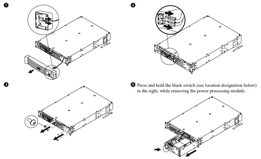
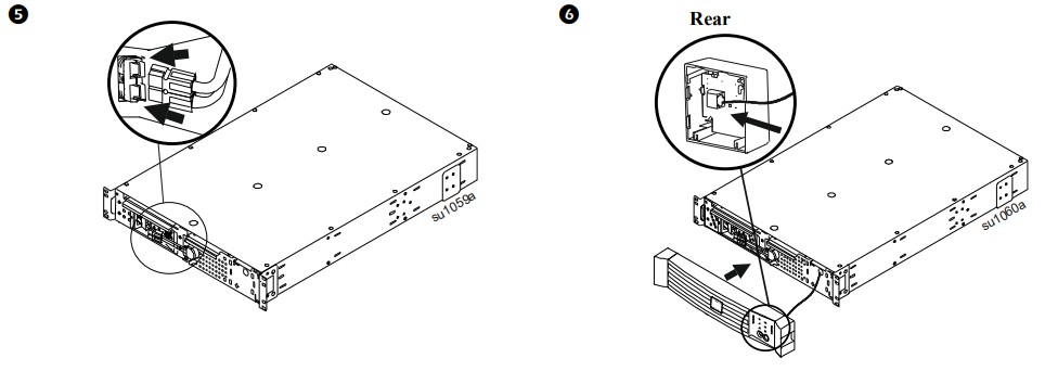
See your dealer or contact APC by Schneider Electric (see Contact Information) for information on replacement batteries.See “Mount the UPS in the Rack and Connect the Battery” on page 4 for details on battery removal and replacement.
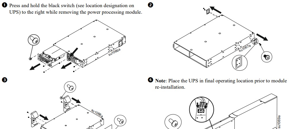
Power Processing Module Replacement
Note: Reverse steps 1-4 for installation of the new module.
Troubleshooting
Use the chart below to solve minor UPS installation and operation problems. Refer to IBM for assistance with complex UPS problems.
| Problem and/or Possible Cause | Solution |
| UPS will not turn on | |
|
UPS is not connected to the utility power supply. |
Check that the power cord from the UPS to the utility power supply is securely connected at both ends. |
| The battery is not connected properly. | Check that the battery connector is fully snapped into position. |
| Very low or no utility voltage. | Check the utility power supply to the UPS by plugging in a table lamp. If the light is very dim, have the utility voltage checked. |
| UPS will not turn off | |
| The front display is not lit, yet the outlets are powered. | Gently attempt to reposition the black switch to the left, and the module will be activated. |
| The black switch is stuck in the Off (right) position. In this position, the switch disables the operation of the power module, and power to the loads is bypassed around the power module. | |
| UPS beeps occasionally | |
| Normal operating UPS beeps when running on battery. | None. The UPS is protecting the connected equipment from occasional utility power irregularities. |
| UPS is not providing expected backup time | |
| The UPS battery is weak due to a recent outage or is near the end of the service life. | Charge the battery. Batteries require recharging after extended outages and wear faster when frequently put into service or when operated at elevated temperatures. If the battery is near the end of the service life, consider replacing the battery even if the Replace Battery LED is not yet illuminated. |
| The output voltage is not meeting expectations | |
| The output voltage “on battery” is too low or too high. | Check that the voltage selection rotary switch is set to the desired level (see Installation).Note: In order to register any modification in voltage selection, the UPS must be turned off and then on again. |
| The output voltage “online” is too high or too low. | The UPS allows a certain range of output voltage to be filtered from the input before it goes to the battery. If this range is too wide for the load equipment, the upper and lower limits can be customized (through software) to your application. |
| Not all outlets are powered | |
| One or more of the outlet groups (labeled ‘1’, ‘2’, and ‘3’) are shut off via the network interface connection. | Access the UPS control panel via the network interface connection and check the status of the outlets. If the settings are not what is expected, change them accordingly and review security settings (password, etc.). |
| 3000 VA, 120 V model only:One or more of the outlet groups are overloaded and the circuit breaker(s) tripped. | The three outlet groups are individually protected by circuit breakers, in some cases lower than the overall limit of the UPS. If any one of these has tripped, reduce the load and/or distribute appropriately among the outlet groups and reset the breaker. |
| Runtime is sufficient, but the low battery alert interval is longer than expected | |
| The UPS perceives there are fewer batteries than are connected and provides a longer alert time. | Configure the UPS via PowerChute to register the number of external battery packs connected. See “User Configurable Items” on page 9 for details. |
| The configured low battery alert interval is longer than necessary or expected. | Configure the UPS via PowerChute to provide an adequate low battery alert interval. See “User Configurable Items” on page 9 for details. |
| The LEDs in the battery bar graph are blinking together | |
| While “online” or “on battery”, the expected remaining runtime is lower than the configured low battery alert interval.Note: The number of blinking LEDs still indicates the relative state of charge of the connected batteries. | If the runtime is too short for a graceful shutdown of the connected equipment, additional battery packs must be connected.If the low battery alert interval is longer than required for a graceful shutdown, configure it appropriately via PowerChute. |
| The battery runtime meter has fallen out of calibration and needs to be re-calibrated. | Program the UPS via PowerChute to conduct a runtime calibration test. |
| All LEDs are illuminated and the UPS emits a constant beeping | |
| Internal UPS fault. | Do not attempt to use the UPS. Replace the power processing module. See “Storage and Maintenance” on page 10 for details. |
| Font panel LEDs flash sequentially | |
| Internal UPS fault. | None. The UPS will restart automatically when utility power returns. |
| All LEDs are off and the UPS is plugged into a wall outlet | |
| The UPS is shut down or the battery is discharged from an extended outage. | None. The UPS will return to normal operation when the power is restored and the battery has a sufficient charge. |
| The overload LED is illuminated and the UPS emits a sustained alarm tone | |
| The UPS is overloaded. The connected equipment is drawing more VA or more Watts than the UPS can sustain. | The connected equipment exceeds the specified “maximum load”. The alarm remains on until the overload is removed. Disconnect nonessential equipment from the UPS to eliminate the overload.The UPS continues to supply power as long as it is online and the circuit breaker does not trip; the UPS will not provide power from batteries in the event of a utility voltage interruption.If a continuous overload occurs while the UPS is on battery, the unit turns off output in order to protect the UPS from possible damage. (See Maximum Power and VA Specifications) |
| The condition persists for a few seconds,
stops, and then repeats approximately every minute. |
Equipment such as laser printers draws a great amount of power in short bursts periodically.For instance, laser printers commonly draw nearly 1000 W of power (varies among different printers) for a few seconds, the draw will then stop, only to resume seconds later.The UPS is then subjected to periodic high power draws and will be briefly overloaded. If the UPS must power a laser printer, be sure the UPS can meet the maximum draw of the laser printer. |
| The replace battery LED is illuminated | |
| Replace battery LED flashes and a short beep is emitted every two seconds to indicate the battery is disconnected. | Check that the battery connectors are fully engaged. |
| Weak battery. | Allow the battery to recharge for 24 hours. Then, perform a self-test. If the problem persists after recharging, replace the battery. |
| The battery self-test has not passed. | The UPS emits short beeps for one minute and the Replace battery LED illuminates. The UPS repeats the alarm every five hours. Perform the self-test procedure after the battery has charged for 24 hours to confirm the Replace battery condition. The alarm stops and the LED clears if the battery passes the self-test. |
| The site wiring fault LED on the rear panel is illuminated (120 V only) | |
| The UPS is plugged into an improperly wired utility power outlet. | Wiring faults detected include missing ground, hot-neutral polarity reversal, and overloaded neutral circuits. Contact a qualified electrician to correct the building wiring. |
| The circuit breaker switches off. | Reduce the load on the UPS by unplugging equipment. Reset the breaker. |
| The AVR LED is illuminated | |
| Your system is experiencing excessive periods of low or high voltage. | Have qualified service personnel check your facility for electrical problems. If the problem continues, contact the utility company for further assistance. |
| The Bypass LED is illuminated | |
| The UPS has briefly directed power around the power processing module during a startup sequence. | Nothing. This is a normal behavior of the UPS during startup. |
| The UPS has directed power around the power processing module because of an internal fault. | Replace the power processing module. See “Storage and Maintenance” on page 10 for details. |
| There is no utility power | |
| There is no utility power and the UPS is off. | Use the Cold Start feature to supply power to the connected equipment from the UPS battery.Press the POWER ON button for one second and release. The UPS will beep briefly and go quiet. Press and hold the POWER ON button again, but for about three seconds. The unit will emit a sustained beep. Release the button during this beep. This will supply immediate power to the UPS and the connected equipment. |
| UPS operates on battery although normal line voltage exists | |
| 230 V models and 1500VA, 120 V model only: UPS input circuit breaker tripped. | To reduce the load on the UPS, unplug equipment and reset the circuit breaker. |
| Very high, low, or distorted line voltage. | Move the UPS to a different outlet on a different circuit, as inexpensive fuel-powered generators may distort the voltage. Test the input voltage with the utility voltage displayed “Basic Operation” on page 8 for details. If acceptable to the connected equipment, reduce the UPS sensitivity. |
| Battery charge and battery load LEDs flash simultaneously | |
| The internal temperature of the UPS has exceeded the allowable threshold for safe operation. | Check that the room temperature is within the specified limits for operation.Check that the UPS is properly installed, allowing for adequate ventilation.Press the black switch on the front of the power processing module to the right. This will shut down the power processing module, leave the UPS on and in bypass mode while confirming whether the high temperature is still present. |
Transport and Service
Transport
- Shut down and disconnect all connected equipment.
- Disconnect the unit from utility power.
- Disconnect all internal and external batteries (if applicable).
- Follow the shipping instructions outlined in the Service section of this manual.
ServiceIf the unit requires service, do not return it to the dealer. Follow these steps:
- Review the Troubleshooting section of the manual to eliminate common problems.
- If the problem persists, contact APC by Schneider Electric Customer Support through the APC by Schneider Electric Web site, www.apc.com.a. Note the model number and serial number and date of purchase. The model and serial numbers arelocated on the rear panel of the unit and are available through the LCD display on select models.b. Call Customer Support and a technician will attempt to solve the problem over the phone. If this is notpossible, the technician will issue a Returned Material Authorization Number (RMA#).c. If the unit is under warranty, the repairs are free.d. Service procedures and returns may vary internationally. Refer to the APC by Schneider Electric Webthe site, www.apc.com for country-specific instructions.
- Pack the unit properly to avoid damage in transit. Never use foam beads for packaging. Damage sustained in transit is not covered under warranty.a. Note: When shipping within the United States, or to the United States always DISCONNECT ONE UPS BATTERY before shipping in compliance with U.S. Department of Transportation (DOT) and IATAregulations. The internal batteries may remain in the UPS.b. Batteries may remain connected in the XBP during shipment. Not all units utilize XLBPs.
- Write the RMA# provided by Customer Support on the outside of the package.
- Return the unit by the insured, prepaid carrier to the address provided by Customer Support.
Limited Factory Warranty
Schneider Electric IT Corporation (SEIT), warrants its products to be free from defects in materials and workmanship for a period of two (2) years from the date of purchase. The SEIT obligation under this warranty is limited to repairing or replacing, at its own sole option, any such defective products. Repair or replacement of a defective product or parts thereof does not extend the original warranty period.This warranty applies only to the original purchaser who must have properly registered the product within 10 days of purchase. Products may be registered online at warranty.apc.com.SEIT shall not be liable under the warranty if its testing and examination disclose that the alleged defect in the product does not exist or was caused by end-user or any third person misuse, negligence, improper installation, testing, operation or use of the product contrary to SEIT recommendations or specifications. Further, SEIT shall not be liable for defects resulting from: 1) unauthorized attempts to repair or modify the product, 2) incorrect or inadequate electrical voltage or connection, 3) inappropriate on-site operation conditions, 4) Acts of God, 5) exposure to the elements, or 6) theft. In no event shall SEIT have any liability under this warranty for any product where the serial number has been altered, defaced, or removed.EXCEPT AS SET FORTH ABOVE, THERE ARE NO WARRANTIES, EXPRESS OR IMPLIED, BY OPERATION OF LAW OR OTHERWISE, APPLICABLE TO PRODUCTS SOLD, SERVICED OR FURNISHED UNDER THIS AGREEMENT OR IN CONNECTION HEREWITH.
SEIT DISCLAIMS ALL IMPLIED WARRANTIES OF MERCHANTABILITY, SATISFACTION, AND FITNESS FOR A PARTICULAR PURPOSE.
SEIT EXPRESS WARRANTIES WILL NOT BE ENLARGED, DIMINISHED, OR AFFECTED BY AND NO OBLIGATION OR LIABILITY WILL ARISE OUT OF, SEIT RENDERING OF TECHNICAL OR OTHER ADVICE OR SERVICE IN CONNECTION WITH THE PRODUCTS.
THE FOREGOING WARRANTIES AND REMEDIES ARE EXCLUSIVE AND IN LIEU OF ALL OTHER WARRANTIES AND REMEDIES. THE WARRANTIES SET FORTH ABOVE CONSTITUTE SEIT SOLE LIABILITY AND PURCHASER EXCLUSIVE REMEDY FOR ANY BREACH OF SUCH WARRANTIES.
SEIT WARRANTIES EXTEND ONLY TO ORIGINAL PURCHASER AND ARE NOT EXTENDED TO ANY THIRD PARTIES.
IN NO EVENT SHALL SEIT, ITS OFFICERS, DIRECTORS, AFFILIATES OR EMPLOYEES BE LIABLE FOR ANY FORM OF INDIRECT, SPECIAL, CONSEQUENTIAL, OR PUNITIVE DAMAGES, ARISING OUT OF THE USE, SERVICE OR INSTALLATION OF THE PRODUCTS, WHETHER SUCH DAMAGES ARISE IN CONTRACT OR TORT, IRRESPECTIVE OF FAULT, NEGLIGENCE, OR STRICT LIABILITY OR WHETHER SEIT HAS BEEN ADVISED IN ADVANCE OF THE POSSIBILITY OF SUCH DAMAGES.
SPECIFICALLY, SEIT IS NOT LIABLE FOR ANY COSTS, SUCH AS LOST PROFITS OR REVENUE,WHETHER DIRECT OR INDIRECT, LOSS OF EQUIPMENT, LOSS OF USE OF EQUIPMENT, LOSS OF SOFTWARE, LOSS OF DATA, COSTS OF SUBSTITUENTS, CLAIMS BY THIRD PARTIES, OROTHERWISE.
NOTHING IN THIS LIMITED WARRANTY SHALL SEEK TO EXCLUDE OR LIMIT SEIT LIABILITY FOR DEATH OR PERSONAL INJURY RESULTING FROM ITS NEGLIGENCE OR ITS FRAUDULENT MISREPRESENTATION OF TO THE EXTENT THAT IT CANNOT BE EXCLUDED OR LIMITED BY APPLICABLE LAW.
To obtain service under warranty you must obtain a Returned Material Authorization (RMA) number from customer support. Customers with warranty claim issues may access the SEIT worldwide customer support network through the APC by Schneider Electric Web site: www.apc.com. Select your country from the country selection drop-down menu. Open the Support tab at the top of the web page to obtain information for customer support in your region. Products must be returned with transportation charges prepaid and must be accompanied by a brief description of the problem encountered and proof of date and place of purchase.
APC by Schneider ElectricWorldwide Customer Support
Customer support for this or any other APC by Schneider Electric product is available at no charge in any of the following ways:
- Visit the APC by Schneider Electric website, www.apc.com to access documents in the APC Knowledge Base and to submit customer support requests.
- www.apc.com (Corporate Headquarters)Connect to localized APC by Schneider Electric website for specific countries, each of which providescustomer support information.
- www.apc.com/support/Global support searching APC Knowledge Base and using e-support.
- Contact the APC by Schneider Electric Customer Support Center by telephone or e-mail.
- Local, country-specific centers: go to www.apc.com/support/contact for contact information.
- For information on how to obtain local customer support, contact the APC by Schneider Electric representative or another distributor from whom you purchased your APC by Schneider Electric product.
Customer support and warranty information are available on the APC website, www.apc.com.© 2021 APC by Schneider Electric. APC, the APC logo, Smart-UPS, and PowerChute are owned by Schneider Electric Industries S.A.S. or their affiliated companies. All other trademarks are property of their respective owners.
Smart-UPS Modular 1500/3000 VA 120/230 Vac Rack-Mount 2U
990-1704C05/2021
References
[xyz-ips snippet=”download-snippet”]