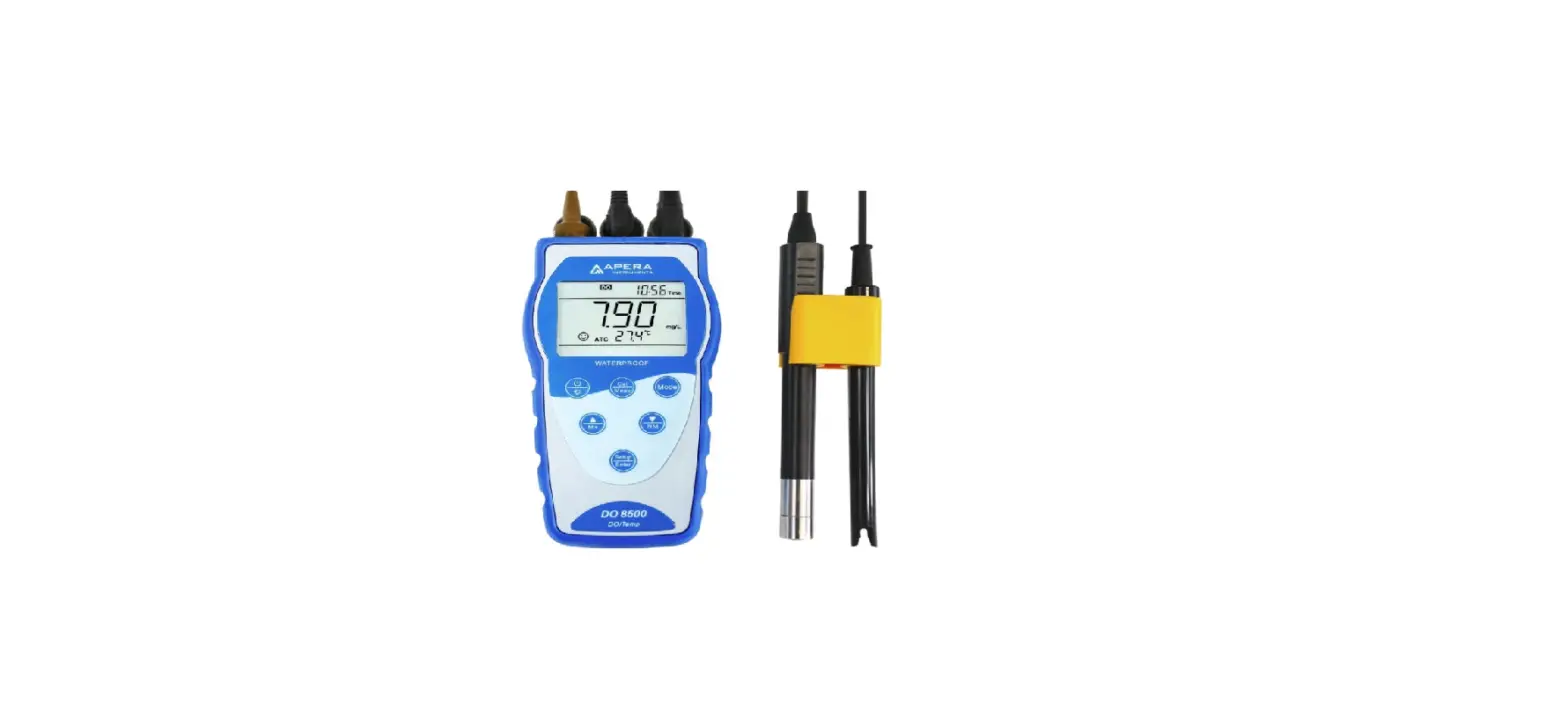
DO8500 Portable Optical Dissolved Oxygen Meter
DO8500Portable Optical Dissolved Oxygen Meter Instruction ManualAPERA INSTRUMENTS (Europe) GmbHwww.aperainst.dev1.2 – 1 –
Table of Contents1 Overview………………………………………………………………………………………………………………- 3 1.1 Luminescent optical sensor. ………………………………………………………………………………- 3 1.2 Intelligent Instrumentation………………………………………………………………………………….- 3 –2 Technical Specifications ………………………………………………………………………………………….- 4 3 Instructions …………………………………………………………………………………………………………..- 5 –3.1 LCD Screen…………………………………………………………………………………………………….- 5 3.2 Key Operation …………………………………………………………………………………………………- 6 3.3 Batteries …………………………………………………………………………………………………………- 7 3.4 Instrument Socket ……………………………………………………………………………………………- 7 3.5 Display mode…………………………………………………………………………………………………..- 7 3.6 Data storage, recall, and clear. …………………………………………………………………………..- 8 3.7 Backlighting …………………………………………………………………………………………………….- 8 3.8 Automatic Power-Off ………………………………………………………………………………………..- 8 4 Optical Dissolved Oxygen Probe………………………………………………………………………………- 9 4.1 Probe Structure ……………………………………………………………………………………………….- 9 4.2 Probe Maintenance ………………………………………………………………………………………….- 9 4.3 Sensor Cap …………………………………………………………………………………………………..- 10 5 Preparation for Calibration …………………………………………………………………………………….- 10 5.1 Dissolved Oxygen Units Selection …………………………………………………………………….- 10 5.2 Resolution Selection………………………………………………………………………………………. – 11 5.3 Temperature Unit Selection …………………………………………………………………………….. – 11 5.4 Air Pressure Compensation …………………………………………………………………………….. – 11 5.5 Salinity Compensation ……………………………………………………………………………………. – 11 6 Calibration…………………………………………………………………………………………………………..- 12 6.1 Saturated Oxygen Calibration…………………………………………………………………………..- 12 6.2 Zero-Oxygen Calibration …………………………………………………………………………………- 12 6.3 Special Notes for Calibration ……………………………………………………………………………- 13 7 Measurement ………………………………………………………………………………………………………- 13 8 Parameter Settings ………………………………………………………………………………………………- 14 9 USB Communication…………………………………………………………………………………………….- 17 10 Complete Kit ……………………………………………………………………………………………………….- 19 10.1 What’s in the box……………………………………………………………………………………………- 19 10.2 Accessories for separate purchase……………………………………………………………………- 19 11 Warranty……………………………………………………………………………………………………………….- 20 12 Trouble Shooting……………………………………………………………………………………………………- 21 11 Appendix A: Oxygen Solubility Table (760mm Hg)……………………………………………………..- 22 12 Appendix B: DO % Calibration Values……………………………………………………………………..- 23 –– 2 –
1 OverviewThank you for purchasing Apera Instruments DO8500 Portable Optical Dissolved Oxygen Meter. The DO8500 measures dissolved oxygen in water using luminescence technology through an optical sensor and displays data with intelligent instrumentation. Compared to conventional electrochemical dissolved oxygen meter, the DO8500 is more accurate and stable, and easier to use.Before you use the instrument, please carefully read the instruction manual to help you properly perform tests and maintainenance.1.1 Luminescent optical sensor. Stability and Accuracy: Oxygen is not consumed during measurements. It is not affected by sample flow rate and thus provides a stable measurement. Easy to Use: No electrolytes and membranes are present in the meter; no warm-up required; frequent calibration is not necessary. Interference-Free: Sensor cap is coated with a light-shielding layer and minimizes the impact from external light sources. The use of non-chemical sensors helps reduce a variety of heavy metal ions interference in the aqueous environment, along with H2S and NH4 and other chemical substances. Long service life. Other than mechanical deterioration (such as scratches to the light shielding layer), the sensor cap has up to 8000 hours of service life. Easy to calibrate and maintain. Probe is equipped with a calibration/storage sleeve, which makes calibration and maintenance more convenient and reliable.1.2 Intelligent Instrumentation Built-in microprocessor chip, featured with Auto. Temperature Compensation, Auto. Air Pressure Compensation, Auto. Salinity Compensation and parameter setting, auto. power off, and low power indication. Meter meets with the requirement of international GLP standards, clock display, manual storage and automatic timing storage. USB data output. Stable reading and automatic locking modes available. Clear large-size LCD display with white backlight. Meets IP57 waterproof rating; In addition, a rugged instrument suitcase is provided.Special Notes Sensor cap surface coating can not withstand high temperatures, so the opticaldissolved oxygen electrode can not test the water of more than 50 . When the electrode is not in use, it should be kept in the storage sleeve, andkeep the sponge in moist, so that the fluorescent cap will not dry out. If the sponge is dry out or the probe is exposed in dry air for more than 8 hours, soak the electrode in tap water for 24~48 hours (see article 4.2), otherwise it may cause unstable measurements or slow response. Before get readings or perform other operations, wait about 30 seconds after meter is powered on.– 3 –
2 Technical Specifications Dynamic Range Resolution
Accuracy
Dissolved Oxygen
Response Time
Calibration Points
Temperature Compensation
Pressure Compensation
Salinity Compensation
Range
Temperature
Resolution
Accuracy
Data Storage
Output
Other
Batteries IP Rating
Dimensions and Weight
Product Certificate
(0-20.00) mg/L (ppm), (0-200.0)% 0.01/0.1mg/L (ppm), 0.1/1%±2% reading or ±0.2 mg/L, whichever is greater±2% reading or ±2% saturation, whichever is greater30 s (25 , 90% response) Saturation Point & Zero OxygenAutomatic, (0 to 50) Automatic, (60 to 120) kPa Manual or automatic, (0 to 45) ppt(0 to 50.0) 0.1 ±0.5500 groups (with time and date) USBAA x 3 (1.5V×3) IP57Meter: 88×170×33 mm/313g With case: 360×270×76 mm/1.3kgRoHs, CE & ISO9001:2015
– 4 –
3 Instructions 3.1 LCD Screen
Fig.-1
Measurement mode
Serial number of storage and prompts of special display mode
Reading/Measured Value
M+ — Measurement to be stored RM — Reading to be recalled
Timing storage
Temperature value and prompts of special display mode
Date.time and prompts of special display mode
Automatic reading lock-up
Units of date and time
ATC–Auto temperature compensation MTC–Manual temperature compensation
Units of measurement
Stability icon of readings
Units of temperature
USB communication
Units during calibration
Low power indication
– 5 –
3.2 Key Operation
Fig.-2
Short press: key press time < 2 s; Long press: key press time> 2 s.
Power on: Press
to turn on. Shutdown: long press
2 seconds off.
First time use: see parameter setting P4.7 & P4.8 to set correct date and time (as Clause 8.3) Special notes: Before get readings or do other operations, wait about 30 seconds after meter powered on.
Table – 1 Key operation and functions
Key Operation
Functions
Short Press
When powered off, press the key to power on In measurement mode: press to turn backlight on or off
Long Press Press and hold for 2 seconds to turn off
Short Press Long Press Short Press Short Press
In measurement mode: press the key to switch unit: %mg/L or %ppmIn the measurement mode: press the key for 2 seconds to enter the calibration modeTo cancel any operation, press to return to measurement mode In measurement mode: press to enter menu mode; In calibration mode: press key to calibrate; In the menu mode: press key to confirm the parameter.
In measurement mode: press
key to change the serial
Short Press orLong Press
number or press
to recall the measurement value.
In recall mode(RM), short press to change serial number of
stored measurement value, or long press to conduct rapidly
change; In the menu mode:press the key to change the serial number or
select the parameter
– 6 –
3.3 Batteries The instrument uses three AA alkaline batteries. Battery life > 200 hours (without backlight). When the display shows symbol as shown in Figure-3, replace the battery.
3.4 Instrument SocketThe instrument socket protected by grey rubber sealing cap, as shown in Figure-4. Eight-pin socket (right) – connect DO electrode. When inserting the probe plug, please insert it after the notch position, and tighten the plug nut. The end face of the socket and the plug connection has the sealing ring, which can effectively maintain the waterproof protection of the socket. BNC socket (left) – connect salinity electrode RCA socket (middle) – connect temperature probe
3.5 Display mode
3.5.1 Main Display Screen If the salinity probe is not connected or salinity is lower than 1ppt, only
the DO value and temp value will be displayed on the LCD screen as shown in Figure-5, DO value: 8.18mg/L; temp. value: 25.2.
When salinity probe is connected and salinity is higher than 1ppt,
salinity will be displayed on right bottom of the LCD screen, as shown
in Figure-6,DO value: 6.97mg/L, Temp value: 25.2; Salinity: 32ppt,
Press
key to switch beteen unit of mg/L%. Or select unit of
mg/L or ppm
in parameter setting P3.1, time displays on top right of LCD screen.
3.5.2 Reading Stability ModeWhen the measured value is stable, the LCD screen displays the icon as shown in Figure-7. If there is no icon or icon flashing,indicates that the measured value is not stable, the measured value should not be read or calibrated.
3.5.3 Auto Lock Mode
In parameter setting P4.3 you can select the auto-lock mode (Off-On) ,
Select On to turn on automatic locking. When the reading is stable
for more than 10 seconds, the meter automatically locks the measured
value and displays the HOLD icon, as shown in Figure – 8.When auto
locked, press
to unlock. Select Off to turn off automatic locking.
– 7 –
Fig.-3 Fig.-4Fig.-5 Fig.-6Fig.-7 Fig.-8
3.6 Data storage, recall, and clear.
3.6.1 Manual storage
When the measurement is stable, press key, the meter will store
measureent value, M+ icon and storage serial number will be displayed
on botton right of LCD sreen, as shown in Figure-9. First group of data
was stored.If connect salinity probe, press
key, M+ icon and
storage serial number will be displayed for 2 seconds, then salinity
displays on LCD screen continously. As shown in Figure-6
Fig.-9
3.6.2 Automatic timing storageSet the storage timing (e.g. 3 minutes) from parameter P4.1, icon displays on LCD screen, the meter enters the timing storage mode. When press key, icon flashes and the first measuring value is stored. After 3 minutes, the 2nd measuring value is stored automaticly. See Figure-10 the meter stores eight measuring values automatically. When press key, icon stops flashing and the meter stops automatic storage. In automatic storage mode, manual storage does not work. Set time 0 in parameter P4.1 to exit from the automatic storage mode.
Fig.-10
3.6.3 Recall stored valueIn the measurement mode, press key to recall the last stored measured value. See Figure 11: Pressing key or key to change the recalled measuring value. Press and holdkey or key to change the recalled measuring value quickly.
3.6.4 Clear stored value Select YES in parameter P4.4 to clear all stored value.
Fig.-11
3.7 Backlighting
The Instruments LCD screen has a white backlight suitable for use in dimly lit environments.
Turning on the backlight will consume more power. There`s two backlighting mode. On and
Off, you can select in the parameter setting P4.5. Select On, press backlight will be on
for a minute then automatically shuts off. Select Off, when the key
is pressed, backlight
will be on and will be off only when is pressed again.
3.8 Automatic Power-OffIn the parameter setting P4.6, you can set the auto power off function (On-Off), select On to turn on auto power off function, the instrument will shut down automatically if no operation within 20 minutes, select Off to disable this function.
– 8 –
4 Optical Dissolved Oxygen Probe4.1 Probe Structure The instruments DO803 optical dissolved oxygen probe has a cable length of 3m and a builtin temperature sensor for automatic temperature compensation. The electrode structure is as shown in Figure.-12
Fig.-12
1. Bottom cover of the calibration sleeve 2. Sponge for water storage 3. Sensor cap4. Calibration/Storage sleeve
5. Locking cap 6. Optical DO electrode 7. O ringImmersion line: The test sample should be above this line
4.2 Probe Maintenance The sensor cap of the optical DO electrode must be kept in a moist environment. If the surface coating of the sensor cap dries out, the measured value will be unstable, or the response will be slow. The electrode calibration sleeve is used to store the probe.(A) Short-term storage (less than 30 days): The probe head is kept in the calibration sleeve. Always keep the sponge inside the calibration sleeve wet. Several drops of clean water should be added to a dry sponge (let the sponge be saturated, but not dripping), and tighten the lock cap, so that the sensor cap is kept in the moistsaturated air.(B) Long-term storage (greater than 30 days): The probe head is kept in the calibration sleeve. Check whether the water storage sponge is moist every 30 days or user can store the electrode in a beaker containing water.(C) Before the first use, unscrew the calibration sleeve to check if the sponge is wet. If the sponge is dry or if the electrode is exposed to dry air for more than 8 hours, the surface coating of the sensor cap may be completely dry. So the electrode should be
– 9 –
immersed in tap water at room temperature 25 for 24 hours. If the water temperature is low, soaking time is 48-72 hours.(D) The sponge can not be allowed to get stained or moldy, otherwise it will consume or produce oxygen. If stained or moldy, please replace it immediately.4.3 Sensor Cap (A) The sensor cap is an important part of the optical DO probe. The surface coating ofthe cap cannot be scratched or mechanically worn. Otherwise, the life of the sensor cap will be reduced or the probe will be damaged. Please pay special attention to it when using the probe.(B) The surface coating of the sensor cap cannot withstand high temperatures, so the optical DO probe can not be tested in water above 50 .(C) If the surface of the sensor cap is contaminated, please do not use alcohol and organic solvents to clean, otherwise it may damage the probe. It can be gently wiped with a soft cloth or paper towels. To disinfect the probe, immerse it in 3% hydrogen peroxide for 15 to 30 minutes and then rinse off with water.(D) The sensor cap has a service life of more than 8000 hours. When the probe is not being used, it does not “bleach” luminescence layer; in addition, the storage time will not reduce the life of the probe, so the actual use time of the sensor cap is far more than a year. The major factor affecting the service life of the sensor cap is the surface coating being damaged under external force. So the key is to protect the sensor cap from external damage.(E) If the sensor cap is damaged or deteriorated, users need to purchase a new one. Every new cap has a set of calibration codes which need to be input into the instrument. The specific input method will be described in the instruction manual of sensor cap.(F) The probe that comes with the instrument can be used directly without the input of the calibration codes. So users should not take off the sensor cap when it is not in use. Nor should one swap the caps from different instruments. When being installed, the sensor cap must be tightened, and the interior can not be contaminated or wet.5 Preparation for Calibration5.1 Dissolved Oxygen Units Selection Dissolved oxygen units displays in two forms: mg / L and %, and ppm and %. Press to switch between mg / L %, or ppm %. Users can choose mg / L or ppm in parameter setting P3.1, but only a percentage (DO%) is displayed in probe calibration.– 10 –
5.2 Resolution Selection The resolution unit can be selected in parameter setting P3.2: 0.01 or 0.1mg/L (ppm), After setting, the meter will display resolution of 0.1 or 1 in according to %.5.3 Temperature Unit Selection The temperature unit can be selected in parameter setting P4.2: or .
5.4 Air Pressure CompensationThe instrument has automatic air pressure compensation function. The instrument has been performed the air pressure calibration before it leaves the factory. So generally users do not have to calibrate the air pressure. If necessary, calibrate it according to standard value measured by aneroid barometer. Refer to parameter setting P3.5 for the procedure of aneroid barometer calibration.
5.5 Salinity CompensationGenerally, salinity of freshwater is 0 to 0.5ppt, salinity of seawater is 35ppt. As the salinity of the solution increases, the level of DO decreases. Refer to parameter setting P3.3, for selection of auto salinity compensation or manual salinity compensation. If manual salinity compensation selected in P3.3, please enter the parameter setting P3.4 to input salinity value (see clause 5.5.1); if auto salinity compensation selected, should connect the salinity electrode, then conduct calibration in parameter setting P3.4 (see clause 5.5.2).
5.5.1 Manual salinity compensation (Hnd) (A) In parameter setting P3.3, select manual salinity compensation(Hnd). Operation refers to P3.3. (B) In parameter setting P3.4, input salinity value (0~45ppt),Operation refers to P3.4. (C) Connect DO electrode to conduct measurement.
5.5.2 Auto salinity compensation (Aut)
(A) Connect salinity electrode to meter;
(B) Switch parameter setting to P3.3, select auto salinity
compensation (Aut), Operation refers to P3.3.
(C) Switch parameter setting to P3.4, press
to enter salinity
calibration mode. Submerge the salinity electrode in
12.88mS/cm conductivity calibration solution, stir gentlely and
allow it to stay in the calibration solution for a while. When the
Fig.-13
– 11 –
reading is stable and
displays on the LCD, press
key to calibrate, LCD
displays correct salinity value (the calibration procedure refer to Figure 13). Press key to return to the measurement mode.
Special notes:
(A) Use 12.88mS/cm conductivity calibration solution to calibrate salinity. If the the standard
solution is wrong, Err icon will be flashing at the bottom right of LCD if
is pressed,
indicating invalid calibration.
(B) Since salinity calibration is done by factory before delivery, so it is not necessary to perform salinity calibration during initial use. Only make salinity calibration when replace with a new electrode, or when the electrode is unused for a long time.(C) For auto salinity compensation, salinity probe must be connected, As shown in figure-14. Users can fit DO probe and salinity probe together into the clip to measure simultaneously.
Fig.-14
6 Calibration6.1 Saturated Oxygen Calibration(A) This procedure requires the use of a calibration sleeve to allow the probe to be calibrated in a humidity-saturated atmosphere(B) Check that the sponge in the calibration sleeve is wet. Attach the calibration sleeve to the probe. Tighten the locking cap. Be careful not to have water droplets on the head of the cap. Wait for 5 to 10 minutes after turning on the instrument. Saturate the air in the calibration sleeve with water vapor. In addition, wait for the temperature to completely stablize. Long press the key to enter the calibration mode, and the CAL is flashing in the upper right corner of the LCD. Wait for the stable icon to appear and stay, press the key to calibrate, once the instrument displays a stable 100%, it is ready to use.6.2 Zero-Oxygen Calibration Zero-Oxygen calibration is only performed when a probe or sensor cap is replaced or the probe has not been used for a long period. It is usually not necessary to conduct zero oxygen calibration. Zero-Oxygen calibration is done by factory before shipment, so it is not necessary to perform a zero-oxygen calibration during initial use. Zero-oxygen calibration should follow these steps:
– 12 –
(A) Preparation of 100ml of oxygen-free water: in the 100ml beaker, weigh 2g anhydrous sodium sulfite (Na2SO3) and add 100ml of pure water or tap water to dissolve. Oxygen-free water is effective within 1 hour.(B) Put the electrode into the oxygen-free water, wait for 3 to 5 minutes after the instrument is turned on, and wait for the temperature and measured value to completely stabilize. The measured value should be very low, 0.1mg / L or so.(C) Long press to enter the calibration mode. The upper right corner of the LCD will flash CAL. Wait for a stable icon. Press and the zero-oxygen calibration is completed.6.3 Special Notes for Calibration (A) Please note that the closer the temperature of the sample solution to the calibrationsolution, the more accurate readings. So it is recommended that the oxygen saturation calibration to be performed according to section 6.1 before use every day. (B) Drying of the surface coating of the sensor cap can adversely affect the stability of the measurement. Please pay special attention to this situation. See Section 4.2 (Probe Maintenance) for details. (C) The instrument has factory default setting function, select YES in parameter setting P3.6, the meter will be calibrated to the theory value.7 Measurement7.1 When measuring, place the probe in sample solution, stir quickly in the solution for a few seconds and rest it to remove bubbles from the measuring surface of the sensor cap. The solution must be above the immersion line of the probe. Note that brief shaking the probe in solution is only to eliminate bubbles. Not like conventional electrochemical electrodes, the measuring via optical dissolved oxygen probes does not require constant stirring of the solution or flowing fluid.7.2 Users can read the measured values when the icon appears and stays. Note that the measurement time is related to temperature. When the solution temperature and the probe temperature is close, it takes about one minute to get the readings stablized. When the solution temperature and the electrode temperature differ a lot, it takes about 3 minutes to reach a stable reading. This is because the reading of dissolved oxygen is heavily influenced by temperature, and the probe senses temperature much more slowly than dissolved oxygen.– 13 –
8 Parameter Settings
Press the press the P3.1, press P4.1,press
key in the measurement mode to enter the parameter setting mode P3.0,
key to switch the menu P3.0 P4.0; In P3.0 mode, press
to enter
to switch submenu P3.1P3.6; In P4.0 mode, press
to enter
to switch submenu P4.1P4.8. See Table 2 for details.
Menu Submenu
P3.1
P3.0 DO parameter
P3.2 P3.3 P3.4
P3.5
P3.6
P4.1
P4.2
P4.3
P4.0 Basic parameter
P4.4 P4.5
P4.6
P4.7
P4.8
Table-2 Parameter Setting List
Parameter
Code
DO Units Selection
/
Resolution Selection
/
Salinity Compensation Mode
/
Salinity Compensation
/
Air Pressure Calibration
Back to Factory Default
Timing Storage
/
Temp. Unit Selection
/
Auto Lock
/
Clear Storage
Auto Backlight
Auto Power Off
Adjust Date
/
Adjust Time
/
Content mg/L–ppm0.01/0.1 mg/L(ppm)Aut–Hnd(0 to 45) ppt (60 to 120) kPaNo–Yes 0:00—Off–On No–YesOn–Off On–Off/ /
– 14 –
DO Parameter setting (press or to switch)
P3.1–Dissolved Oxygen Unit (mg/L–ppm)
1. In P3.0 mode, press the
key to enter P3.1 mode.
2. Press the
key, mg / L flashes, press the
mg/L ppm, press
to confirm.
key to select
3. Press
to enter P3.2 mode, or press
measurement mode.
to return to
P3.2–Resolution (0.01-0.1mg/L)
1.Press the
key, 0.01 flashes, press the
resolution (0.01-0.1mg/L), press
to confirm.
key to select
2. Press
to enter P3.3 mode, or press
measurement mode.
to return to
P3.3–Salinity Compensation Mode (Aut-Hnd)
1. Press the
key, Aut flashes.Press
to select auto salinity
compensation (Aut) or manual salinity compensation(Hnd),Press
key to confirm.
2. Press
to enter P3.4 mode,or press
measurement mode.
to return to
P3.4–Salinity Compensation (0~45 ppt) 1. Press the key to input salinity value, when manual salinitycompensation selected in P3.3, operation refers to clause 5.5.1. 2. Press the key to enter salinity calibration mode, when autosalinity compensation was selected in P3.3, operation refers to clause 5.5.2
P3.5–Air Pressure Calibration (60 to 120 kPa) 1. Press the key, 101.3 flashes, according to standard pressurevalue of aneroid barometer. Press or key to adjust, Press key to confirm. 2. Press to enter P3.6 mode, or press to return to measurement mode.
P3.6–Back to Factory Default (No–Yes)
Press
key, No flashes, Press
key to select No Yes,
Press key to confirm. Meter returns to measurement mode.
No–cancel restore. Yes–restore
– 15 –
Basic Parameter setting (press or
to switch)
P4.1–Adjust timing storage time
1. In P4.0 mode, Press
key to enter P4.1 mode.
2. Press
key,”00″ flashes, Press
or
key to adjust
minute (0~59); Press
key,”0″ flashes,Press
or to
adjust hour (0~99), Press
key to confirm;
3. Press key to enter P4.2 mode, or measurement mode.
key to return to
P4.2– temperature unit (–)
1. Press
key, flashes, Press
key to select , Press
key to confirm.
2. Press key to enter P4.3 mode, or measurement mode.
key to return to
P4.3–Auto Lock (Off–On)
1. Press
key, Off flashes,Press
key to select OffOn,
Press
key to confirm.
Off–turn off lock function; On–turn on lock function (If reading stays stable for more than 10 seconds, it auto locks).
2. Press key to enter P4.4 mode, or measurement mode.
key to return to
P4.4. Clear all the stored value No–Yes
1. Press
key, ” No ” flashes, then press
key to select
between No–Yes, press
key to confirm
No: not delete, Yes: delete.
2. After confirm the parameter, press
to enter in P4.5 mode or
press
key to return to the measurement mode.
P4.5–Auto Backlight (On–Off)
1. Press
key, On flashes, Press
key to select OnOff,
Press
key to confirm.
On turn on auto backlight off function, Off turn off auto backlight off function.
2. Press
key to enter P4.6 mode, or press
measurement mode.
key to return to
– 16 –
P4.6–Auto Power Off (On–Off)
1. Press
key, On flashesPress
key to select OnOff
press
key to confirm.
On–turn on auto power off function Off–turn off auto power off function.
2. Press
key to enter P4.7 mode, or press
key to return to
measurement mode.
P4.7. Adjust date
1. Press
key, “Month” flashes, then press
key, “Date”
flashes, then press
key, “Year” flashes. When the number
flashes, press
key or
key to adjust date, then press
key to confirm.
2. Press
key to enter in P4.8 mode or press
key to return
to the measurement mode.
P4.8. Adjust time
1. Press
key, “15” flashes, then press
key, “06” flashes.
When the number flashes, press
key and
key to adjust
time, and then press
to confirm.
2. After confirm the parameter, press measurement mode.
key to to return to the
9 USB CommunicationThe meter uses “PC-Link” software with USB communication function. The port is USB. Software interface (as shown in Figure 15.) –Stored value display area (a) Press “Download” to download the data from the meter to the computer, measuring date.time.value and temperature and so on. (b) Connect meter to computer, then press key, or set the timing sorage function, The measuring information will be displayed on the computer through USB, and will not be stored in the meter as shown in Figure 15. — Mode and Serial Number — Parameter setting information — Port type and press key– 17 –
The port number is software connected to computer, each computer recognizes different port number, as shown in Figure 15, the port number is COM3. Open/Close — press this key to turn on or off software, Icon indicates that software is activated. Refresh — press this key to reset COM port to COM1 SyncTime — press this key to set time of meter same with computer. Download — press this key to download the data from the meter to the computer, Clear — press this key to clear all the stored value. Export — press this key to export the stored value to Microsoft Excel file. Exit — press this key, PC-Link program exists from the computer interface.Fig.-15 9.2. Run software Load PC-Link to the computer, open “PC-Link” file, which inclucing PCLink software file and driver Compressor file, Generally, open PCLlink file directly. If the meter can`t be connected to software, please install USB driver firstly. 9.3. Connection port selection Connect USB cable to the meter and the computer, open PC-Link program, program interface shows in computure, press the arrow icon next to COM1, then pres Open key, LCD will displays , or please confirm the port number in ” device manager” of the computer. 9.4. Software operation 9.1.1 Upload the stored value Press “Download” key, all the data stored in the meter is downloaded to the computer. The– 18 –
data will be listed by category.
9.1.2 Storage during operation
(a) During operation, press
key to store or set timing storage. The measuring
information is downloaded to the computer through USB and will not be stored in the meter.
(b) The stored mode and unit during operation is same as the data shown on the meter.
press to change.
9.1.3 Data processing Press “Export” key to export the stored value to Microsoft Excel file and then analyze or print the stored data.
10 Complete Kit10.1 What’s in the box Content1. DO8500 Portable Optical Dissolved Oxygen Meter 2 DO803 Optical Dissolved Oxygen Probe 3 Probe Calibration/storge sleeve 4 Conductivity Electrode 2301-3M 5 PC-Link Communication Software disk 6 USB Communication Cable 7 Combined electrode clip 8 Small Screwdriver 9 Carrying Case 10 Sponge for Water Storage (spare) 11 Instruction Manual 10.2 Accessories for separate purchase
Quantity 1 1 1 1 1 1 1 1 1 4 1
Model DO803
Name Optical DO probe (3m cablewith sensor cap and calibration sleeve)
DO810 Optical DO probe (10m cable, with sensor cap and calibration sleeve)
DO8032 Sensor cap
DO8031 Calibration/Storage sleeve
– 19 –
11 Warranty 11.1 We warrant this instrument to be free from defects in material and workmanship and agree to repair or replace free of charge, at option of APERA INSTRUMENTS (Europe) GmbH, any malfunctioned or damaged product attributable to responsibility of APERA INSTRUMENTS (Europe) GmbH for a period of 3 YEARS from the date of purchase. That of DO803 optical DO probe (excluding sensor cap) is 2 years from the date of purchase. That of DO8032 sensor cap is 1 year from the date of purchase. 11.2 Damage and malfunction of the product caused by the following reasons are not covered by the warranty: (A) Fails to install, operate, or use the product in accordance with the instruction manual, orif the product is damaged by abuse or incorrect use; (B) The sensor cap is damaged by external force and can not work; or the electrode cableis damaged or twisted due to external force; (C) Fails to maintain the product in accordance with the requirements of this manual andthe industry standard process; (D) Any unauthorized repairs, and the use of defective or incorrect components to repair theproduct; (E) Any modification of the product unauthorized by the Company. 11.3 Product Warranty Period is the free of charge service time for the user who purchase the product, not the service life of the instrument or the probe.– 20 –
12 Trouble Shooting
Error
Solutions
The instrument does not turn on
1. The battery is not installed correctly. Check the polarity. 2. Battery low voltage, replace the battery. 3. Instrument freezes. Unplug the battery and then install.
1. Check calibration procedure: correct atmospheric pressure,
salinity input and temperature.
The instrument can 2. The measured value is not stable, prolong the stabilization
not calibrate
time, until the demonstration then presses the key.
3. Check the sensor cap. If it is contaminated, it can be cleaned; if
dry, it can be hydrated; if damaged it can be replaced.
1.Check whether the temperature is stable, the salinity input and
barometric pressure are accurate.
2. If the probe calibration is not good, recalibrate.
DO readings are not 3. Check the sensor cap. If it is contaminated, it can be cleaned;
accurate
if dry, it can be hydrated; if damaged it can be replaced.
4. Unscrew the sensor cap, check whether there is moisture
inside, if so, wipe off, dry, and tighten it.
The display value stays 200% or 20.0 mg/L. No change
1. Check whether the concentration of the sample is higher than 200% or 20.0 mg / L (ppm).2. Check if the temperature reading is accurate. 3. If the probe calibration is not good, recalibrate. 4. Check the sensor cap. If it is contaminated, it can be cleaned; ifdry, it can be hydrated; if damaged, it can be replaced.
– 21 –
11 Appendix A: Oxygen Solubility Table (760mm Hg)
Temp °C0.0 1.0 2.0 3.0 4.0 5.0 6.0 7.0 8.0 9.0 10.0 11.0 12.0 13.0 14.0 15.0 16.0 17.0 18.0 19.0 20.0 21.0 22.0 23.0 24.0 25.0 26.0 27.0 28.0 29.0 30.0 31.0 32.0 33.0 34.0 35.0 36.0 37.0 38.0 39.0 40.0 41.0 42.0 43.0 44.0 45.0
Chlority: 0 Salinity: 014.62 14.22 13.83 13.46 13.11 12.77 12.45 12.14 11.84 11.56 11.29 11.03 10.78 10.54 10.31 10.08 9.87 9.67 9.47 9.28 9.09 8.92 8.74 8.58 8.42 8.26 8.11 7.97 7.83 7.69 7.56 7.43 7.31 7.18 7.07 6.95 6.84 6.73 6.62 6.52 6.41 6.31 6.21 6.12 6.02 5.93
5.0 ppt 9.0 ppt13.73 13.36 13.00 12.66 12.34 12.02 11.73 11.44 11.17 10.91 10.66 10.42 10.18 9.96 9.75 9.54 9.34 9.15 8.97 8.79 8.62 8.46 8.30 8.14 7.99 7.85 7.71 7.58 7.44 7.32 7.19 7.07 6.96 6.84 6.73 6.62 6.52 6.42 6.32 6.22 6.12 6.03 5.93 5.84 5.75 5.67
10.0 ppt 18.1 ppt12.89 12.55 12.22 11.91 11.61 11.32 11.05 10.78 10.53 10.29 10.06 9.84 9.62 9.42 9.22 9.03 8.84 8.67 8.50 8.33 8.17 8.02 7.87 7.73 7.59 7.46 7.33 7.20 7.08 6.93 6.85 6.73 6.62 6.52 6.42 6.31 6.22 6.12 6.03 5.98 5.84 5.75 5.67 5.58 5.50 5.41
15.0 ppt 27.1 ppt12.10 11.78 11.48 11.20 10.92 10.66 10.40 10.16 9.93 9.71 9.49 9.29 9.09 8.90 8.72 8.54 8.37 8.21 8.05 7.90 7.75 7.61 7.47 7.34 7.21 7.08 6.96 6.85 6.73 6.62 6.51 6.41 6.31 6.21 6.11 6.02 5.93 5.84 5.75 5.66 5.58 5.49 5.41 5.33 5.25 5.17
20.0 ppt 36.1 ppt11.36 11.07 10.79 10.53 10.27 10.03 9.80 9.58 9.36 9.16 8.96 8.77 8.59 8.41 8.24 8.08 7.92 7.77 7.62 7.48 7.35 7.21 7.09 6.96 6.84 6.72 6.62 6.51 6.40 6.30 6.20 6.10 6.01 5.91 5.82 5.73 5.65 5.56 5.48 5.40 5.32 5.24 5.17 5.09 5.02 4.94
25.0 ppt 45.2 ppt10.66 10.39 10.14 9.90 9.66 9.44 9.23 9.02 8.83 8.64 8.45 8.28 8.11 7.95 7.79 7.64 7.50 7.36 7.22 7.09 6.96 6.84 6.72 6.61 6.50 6.39 6.28 6.18 6.09 5.99 5.90 5.81 5.72 5.63 5.55 5.46 5.38 5.31 5.23 5.15 5.08 5.01 4.93 4.86 4.79 4.72
– 22 –
Salinity = Dissolved salts in water. Chlorinity = Measure of chloride content, by mass, of water. S () = 1.80655 x Chlorinity ()
12 Appendix B: DO % Calibration Values
Cal. value D.O. 10%1% 100% 99% 98% 97% 96% 95% 94% 93% 92% 91% 90% 89% 88% 87%
in Hg 30.22 29.92 29.62 29.32 29.02 28.72 28.43 28.13 27.83 27.53 27.23 26.93 26.63 26.33 26.03
PressuremmHg kPa 767.6 102.34 760.0 101.33 752.4 100.31 744.8 99.30 737.2 98.29 729.6 97.27 722.0 96.26 714.4 95.25 706.8 94.23 699.2 93.22 691.6 92.21 684.0 91.19 676.4 90.18 668.8 89.17 661.2 88.15
mbar 1023.38
Cal. valueD.O. 8%6%
1013.25 85%
1003.12 84%
992.99 83%
982.85 82%
972.72 81%
962.59 80%
952.46 79%
942.32 78%
932.19 77%
922.06 76%
911.93 75%
901.79 74%
891.66 73%
881.53 72%
in Hg 25.73 25.43 25.13 24.83 24.54 24.24 23.94 23.64 23.34 23.04 22.74 22.44 22.14 21.84 21.54
PressuremmHg kPa 653.6 87.14 646.0 86.13 638.4 85.11 630.8 84.10 623.2 83.09 615.6 82.07 608.0 81.06 600.4 80.05 592.8 79.03 585.2 78.02 577.6 77.01 570.0 75.99 562.4 74.98 554.8 73.97 547.2 72.95
mbar 871.40 861.26 851.13 841.00 830.87 820.73 810.60 800.47 790.34 780.20 770.07 759.94 749.81 739.67 729.54
 report this ad
APERA INSTRUMENTS (Europe) GmbH Address: Wilhelm-Muthmann-Str. 18 42329 Wuppertal Germany Tel: +49 202 51988998 Email: info@aperainst.de Website: www.aperainst.de– 23 –
References
[xyz-ips snippet=”download-snippet”]