
ELECTRIC HEIGHT-ADJUSTED SIT TO STAND DESKVortex Series 2-leg Desk Assembly GuideFor desk with underframe Model No. AL4628-XX REV-1509A
IMPORTANT SAFETY INSTRUCTIONS
WARNING –When using electric appliances, basic precautions should always be followed, including the following:
a) Read all the instructions before using the appliance.b) To reduce the risk of injury, close supervision is necessary when an appliance is used near children.c) Do not contact moving parts.d) Only use attachments recommended or sold by the manufacturer.e) Do not use outdoors.f) To disconnect, turn all controls to the off (“O”) position, then remove plug from outlet.g) Do not unplug by pulling on cord. To unplug, grasp the plug, not the cord. Unplug from outlet when not in use and before servicing or cleaningh) Do not operate any appliance with a damaged cord or plug, or after the appliance malfunctions or is dropped or damaged in any manner. Return appliance to the nearest authorized service facility for examination, repair, or electrical or mechanical adjustment.i) Connect to a properly grounded outlet only. See grounding Instructions below.
GROUNDING INSTRUCTIONS
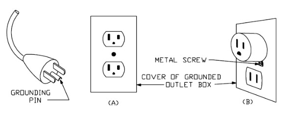
This appliance must be grounded. In the event of malfunction or breakdown, grounding provides a path of least resistance for electric current to reduce the risk of electric shock. This appliance is equipped with a cord having an equipment-grounding conductor and a grounding plug. The plug must be plugged into an appropriate outlet that is properly installed and grounded in accordance with all local codes and ordinances. This appliance is for use on a nominal 120 V circuit, and has a grounding plug that looks like the plug illustrated in sketch A. A temporary adaptor, which looks like the adaptor illustrated in sketches B and C, may be used to connect this plug to a 2-pole receptacle as shown in sketch B if a properly grounded outlet is not available. The temporary adaptor should be used only until a properly grounded outlet can be installed by a qualified electrician. The green-colored rigid ear, lug, and the like, extending from the adaptor must be connected to a permanent ground such as a properly grounded outlet box cover. Whenever the adaptor is used, it must be held in place by the metal screw.
CAUTION, USE & LIABILITY
CAUTIONMake sure no obstacles are in the desk’s path. Make sure the desk is not touching any walls. Make sure all cords are of appropriate lengths to accommodate the change in desk height.
 Keep children away from electric sit-to-stand desks, control units, and handsets.
Keep all electrical components away from liquids.
Do not sit or stand on desk. Do not crawl or lie under desk.
Do not place any objects taller than 20” underneath desk.
Do not open any of the components –lifting columns, control box, or controller. There is a risk of electric shock.
USE & LIABILITY
This sit-to-stand adjustable desk has electric motors and is designed for use in an indoor environment and dry work areas only. The desk height is adjustable so that it can be positioned at the most suitable height. Any other use is at the user’s risk. Under no circumstances does the manufacturer accept warranty claims or liability claims for damages caused from improper use or handling of the desk.
PARTS & HARDWARE
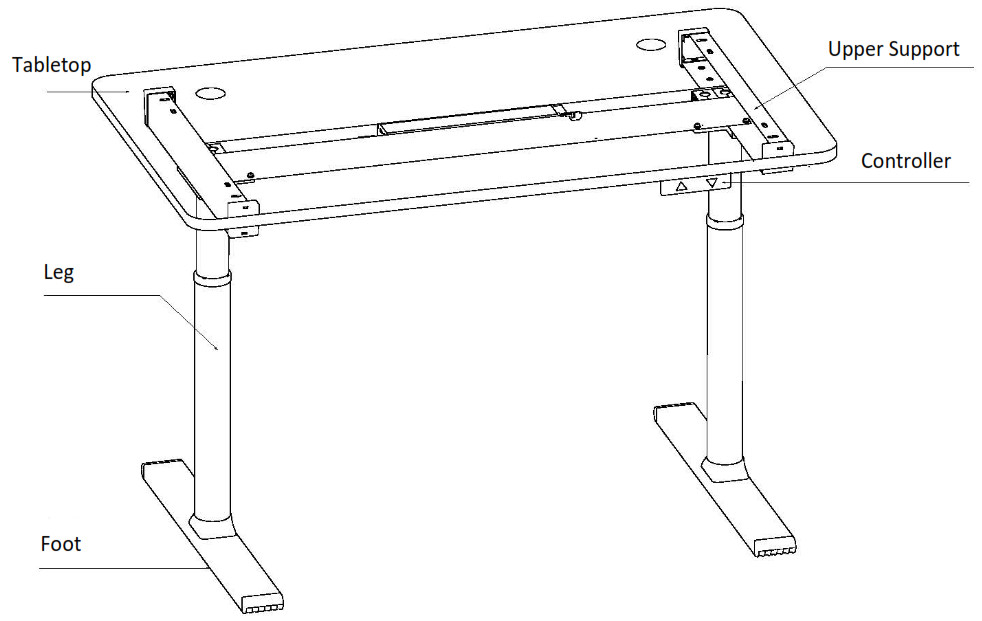
PARTS DIAGRAM
PARTS LIST
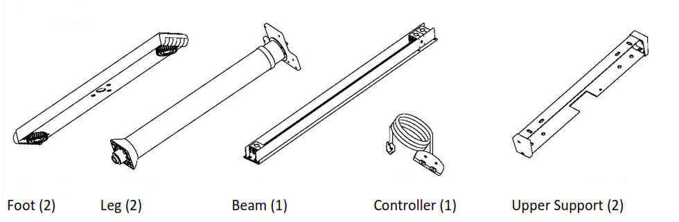
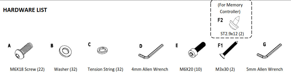
HARDWARE LIST
ASSEMBLY INSTRUCTIONS
BEFORE YOU BEGIN
- Layout all components and hardware to ensure that you have all the parts listed on the parts on page 5.
- Desk weighs close to 100 lbs. Two people are needed to turn or move desk and some of its components. When turning or moving the assembled desk, grab it by UPPER SUPPORTS (not desktop).
- Assemble on soft and non-abrasive surface to avoid scratch or damage to the desktop.
STEP 1Lay the lower support (foot) flat on the floor and secure it to the leg with Screw E as illustrated below. Make sure to use longer socket-headed BLACK Screw E not shorter dome-headed Screw A.
The foot is hollow. In the unlikely event that a screw or washer falls into the foot, you can get it out by unscrewing the leveling stud and prying open the plastic ender with a flat screwdriver. You may also choose not to do anything as extras are provided.
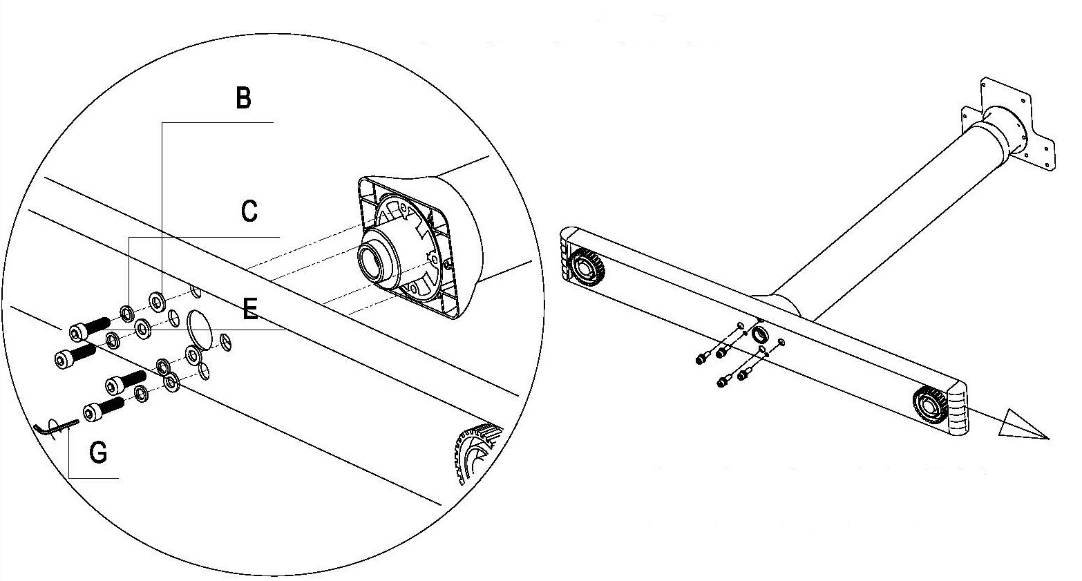
STEP 2Remove the protective cap and insert the hexagon spindle into gearbox on the beam. Please note the marking R and L on the beam and legs. Right leg should connect to right side of the beam, and left leg to left side of the beam.
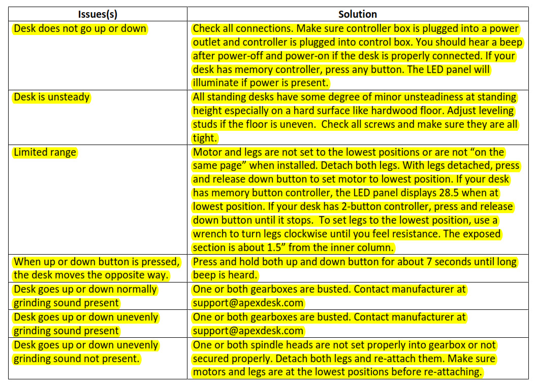
VERY IMPORTANT:Minor adjustment to the spindle head may be needed to set it properly into gearbox. Use a tool like a wrench to turn the spindle head slightly left or right if needed. If you have tested the motor before attaching both legs, make sure to set the motor to the lowest position before attaching legs. Limited range will happen if motor and legs are not set the lowest position, and not “on the same page”. Refer to the troubleshooting section for more info if limited range occurs.
TIP: Attach leg one at a time. Some users find it easier to attach legs by doing the opposite of what is illustrated below. Place the beam upside down on the floor exposing the female socket of the gearbox and push spindle head into the gearbox while turning the leg slightly left and right. Please remember to turn the assembled frame over to its upright position before securing the legs to the beam. The screws should be in from beam side.
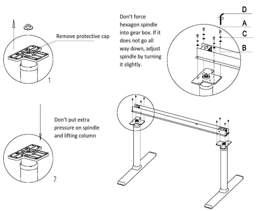
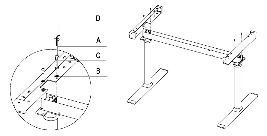
STEP 3Use Screw A to secure two upper supports to the beam.
STEP 4 (Mounting matching top from us)
Lay the tabletop on a soft and non-abrasive surface. Carefully move the underframe onto the top, align the holes on the upper supports to the pre-drilled anchors on the top. Secure the top with Screw A. Don’t overtighten the screws.
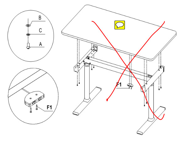
Use longer Screw F1 to mount non-memory controller and shorter Screw F2 for the memory controller. If F1 Screw is used to mount the memory controller, it will go thru the top. Please note that pre-drilled holes are only available on the right side. The non-memorycontroller looks identical on both sides. The upper side of the non- memory controller is labeled “Attach this side to tabletop”.
STEP 4-1 (Mounting your own top)
Optional: Find a separate hardware bag labeled “Anchors for top”. Install those anchors to your own top, and follow instructions STEP 4.
Some users choose not to install anchors and simply use their own wood screws to mount Support Brackets to the top. Those wood screws are not provided. Please check the length of the screws before mounting and make sure that they don’t go through the top. For best stability, the underframe should be centered with support brackets about 2” to 3” from the edge.
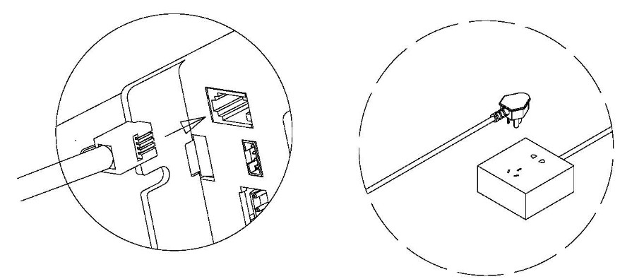
STEP 5Connect the controller to control box. Connect power to a wall plug. If the desk is unsteady, check all screws and make sure they are all tight, and make adjustments to the leveling studs. Please note that minor unsteadiness is common for all standing desks at standing height especially when it is on a hard surface like a hardwood floor.
Memory Function Controller for Desk Underframe Model# AL4628-2M
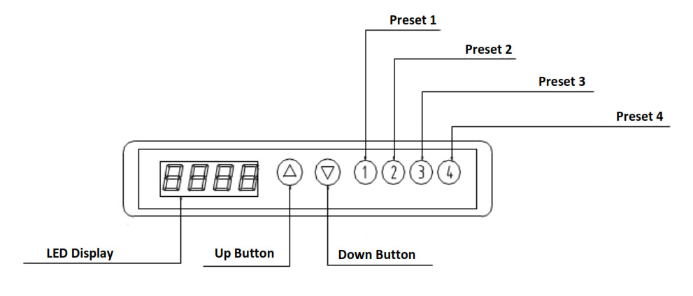
a. LED panel displays minimum height of 28.5” and maximum height of 46.6”b. Factory default settings for four memory buttons are 32.1”, 35.7”, 39.3” and 42.9” respectively.c. To set your own height, press up or down button until the desk reaches the desired height, press and hold memory button until you hear two beeps. Factory setting will be erased once you set your own.d. LED light turns off by itself if inactive for 5 seconds and turns back on when any button is pressed.
TROUBLESHOOTING
CARE INSTRUCTIONS
Recommend checking the screws and bolts several times a year to ensure they stay tight.For all surfaces: wipe clean with a damp cloth and a weak cleaning solution, then dry with a clean and dry cloth.
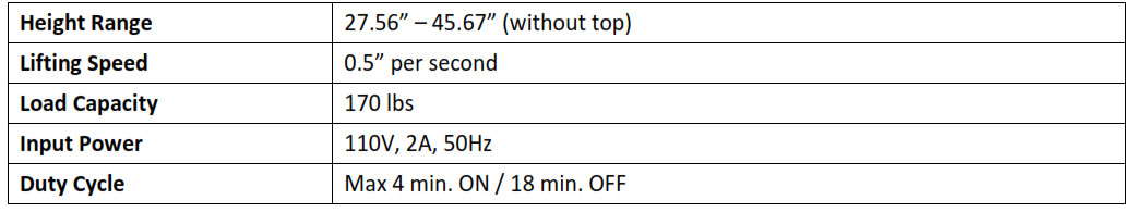
TECHNICAL SPECIFICATIONS
WARRANTY INFORMATION
SCOPE OF WARRANTYApex Furniture LLC (“ApexDesk”) warrants to the original purchaser its new desk (except for components not warranted under “Exclusions”) manufactured by ApexDesk to be free from defects in material and workmanship under normal use and service. ApexDesk’s obligation under this warranty is limited to the repair or replacement, at ApexDesk’s sole option, of the parts or products the defect of which are reported to ApexDesk within the applicable warranty period and which, upon examination by ApexDesk, prove to be defective.
APPLICABLE WARRANTY PERIODThe applicable warranty period, measured from the date of delivery to the original user, shall be two (2) years on motor and moving parts, five (5) years on steel frame for all warranted desks.
EXCLUSIONSThis limited warranty does not cover and ApexDesk shall not be liable for the following: (1)repairs and replacements because of misuse, abuse, negligence, alteration, accident, freight damage, or tampering; (2) products which are not installed, used, stored and properly cleaned as required in the ApexDesk “Assembly Guide” for this product; (3) products considered to be of a consumable nature; (4) Shipping to or from repair center; (5) accessories or parts not manufactured by ApexDesk; (6) charges by anyone for adjustments, repairs, replacement parts, installation, or other work performed upon or in connection with such products which is not expressly authorized in writing in advance by ApexDesk.
EXCLUSIVE REMEDYApexDesk’s only obligation under this warranty is the repair or replacement of defective parts. ApexDesk shall not be liable for any direct, special, indirect, incidental, exemplary, or consequential damages or delay, including, but not limited to, damages for loss of profits or loss of use.
CONTACT INFORMATION
Apex Furniture LLC (“ApexDesk”)18467 Railroad StreetCity of Industry, CA 91748Email: (877) 516-DESKwww.apexdesk.com
For technical assistance, please call us or visit us at www.apexdesk.com/support.
ApexDesk AL4628-XX Electric Height Adjusted Sit to Stand Desk Assembly Guide – ApexDesk AL4628-XX Electric Height Adjusted Sit to Stand Desk Assembly Guide –
[xyz-ips snippet=”download-snippet”]