 Model E070 DehumidifierInstallation Instructions
SAFETY INSTRUCTIONS
![]() WARNING
WARNING
- 120 Volts may cause serious injury from electric shock. Disconnect electrical power before starting installation or servicing. Leave the power disconnected until installation/service is completed.
- Sharp edges may cause serious injury from cuts. Use care when cutting plenum openings and handling ductwork.
- Dropping may cause personal injury or equipment damage. Handle with care and follow installation instructions.
![]() CAUTION
CAUTION
- Read all instructions before beginning installation.
- Improper installation may cause property damage or injury. Installation, service, and maintenance must be performed by a qualified service technician.
- Do not use in pool applications. Pool chemicals can damage the dehumidifier.
- Do not use solvents or cleaners on or near the circuit board. Chemicals can damage circuit board components.
- Wait 24 hours before running the unit if it was not shipped or stored in the upright position.
- Do not use dehumidification to prevent window condensation in the winter.To address window condensation, use ventilation to lower indoor humidity in the winter.
- This appliance is not intended for use by persons (including children) with reduced physical, sensory or mental capabilities, or lack of experience and knowledge unless they have been given supervision or instruction concerning the use of the appliance by a person responsible for their safety.
- Children should be supervised to ensure that they do not play with the appliance.
- If the supply cord is damaged, it must be replaced by a special cord or assembly available from the manufacturer or its service agent.
READ AND SAVE THESE INSTRUCTIONS
SPECIFICATIONS
|
Model E070 |
|
| Unit Weight | 56 lbs. |
| Shipping Weight | 72 lbs. |
| Capacity: ARAM DH-1-2008 80°F. 60% RH Conditions | 70 pints per day © 200 CFM |
| Power: 115 VAC, Single Phase, 60Hz | 5.8 Amps operating current |
| Dehumidifier Inlet Air Conditions | Dehumidification: 50°F — 104°F, 40°F dew point minimumVentilation: 40°F —140°F, 0%RH — 99%RH loon-condensing) |
| Filter | MERV 8. washable |
| Airflow | 200 CFM |
SET UP DEHUMIDIFIER FOR INSTALLATION
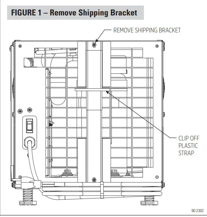
![]() IMPORTANT: Cut the strap securing the compressor shipping support bracket and remove the strap and shipping bracket. See Figure 1.
IMPORTANT: Cut the strap securing the compressor shipping support bracket and remove the strap and shipping bracket. See Figure 1.
PACKAGING CONTENT
- Dehumidifier
- Inlet/Outlet Collars
- Literaturea . Installation Instructionsb. Owner’s Manual
- Parts Baga . #10 x 1/2 Screws (9)b . Threaded Barbed Fitting for Drain Connectionsc . Torx Bit
- 10 foot, 3/4” Drain Tube
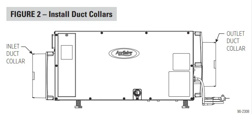
DUCT COLLARS
Use the screws in the parts bag to attach the duct collars to the inlet and outlet of the dehumidifier. See Figure 2.
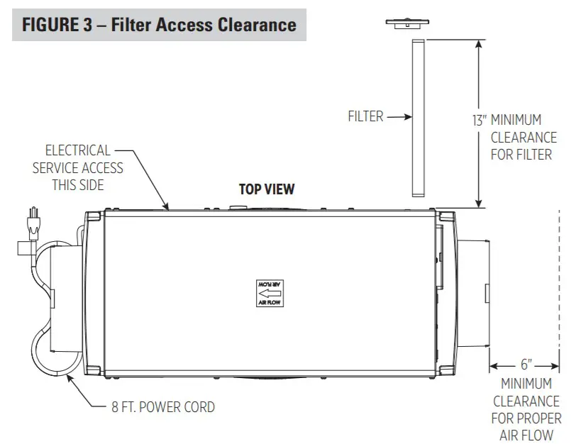
LOCATION CONSIDERATIONS
- Allow sufficient clearance for filter removal and to prevent airflow obstruction
- Electrical service access will require the removal of the side panel shown.Allow sufficient space for service on this side of the unit.
INSTALLATION
LEVELING
The feet can be adjusted to level the unit, and if required, to accommodate drain fittings and a secondary condensate pan.Leveling is required to ensure proper drainage from the dehumidifier. See Figure 4.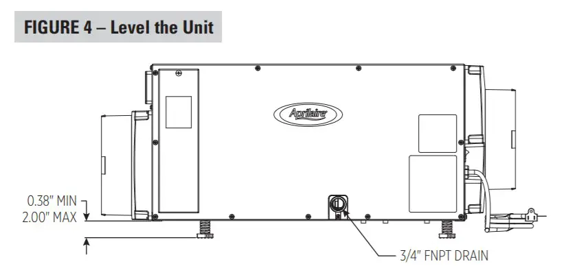
DUCTWORK INSTALLATION
Adding 5-10 feet of insulated ductwork to the inlet and outlet of the dehumidifier will ensure dehumidified air is circulated throughout the crawlspace and will reduce the noise level of the dehumidifier. Point the inlet and outlet ducts in opposite directions to minimize recirculation of dehumidified air.
- The maximum recommended total duct length is 100 feet.
- To avoid pulling in dirt and other particles, do not lay intake duct on the floor of the crawl space.
NOTE: This dehumidifier is designed for crawl space and stand-alone applications only.Do not duct to an HVAC system.
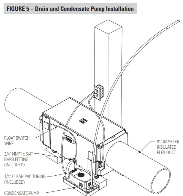
DRAIN TUBING AND CONDENSATE PUMP INSTALLATION
The drain outlet on the dehumidifier can be plumbed directly to a condensate pump (see Figure 5) using the provided 3/4” MNPT x 3/4” hose barb fitting and 3/4” clear PVC tubing. Always maintain a constant downward slope from the dehumidifier to the condensate pump.NOTE: PTFE thread seal tape is recommended for the threaded connection.Hand tightens only. The 4856 condensate pump is capable of lifting water up to 22 feet. The dehumidifier can be elevated (while remaining level) to increase the downward slope for proper draining.Wire the float switch terminals to the normally closed contacts on the condensate pump (see Figure 6).
 |
 |
MODEL 76 – CRAWL SPACE CONTROL AND WIRING

NOTE: Use 18-22 AWG wire for control wiring.Used as a crawl space control (or remote control), the Model 76 is mounted in the living space while the dehumidifier is located in the crawl space.When the dehumidifier is powered, the display on the dehumidifier control will show “REMOTE” to indicate that the remote control is being used. The RH shown on Model 76 is the RH measured at the dehumidifier.NOTE: Air Cycling is not an option when using a Model 76 as a remote control.
AIR CYCLING
The dehumidifier has an optional ventilation feature that can be used to circulate air through the dehumidifier, to promote uniform humidity levels throughout the space.When this feature is enabled, the dehumidifier fan can be set to run from 0 minutes (no air cycling) to 60 minutes (continuous) per hour. See VENTILATION / AIR CYCLING in the SYSTEM SET-UP, CHECK & START-UP section on page 7.NOTE: The onboard control must be used when Air Cycling.
SYSTEM SET-UP, CHECK & START-UP
If using a Model 76 Remote Control and/or the Air Cycling feature, proceed to Step 1 below. If not using either feature, proceed to SYSTEM CHECK on page 7.
- Check all wiring.
- Make sure the wire access cover has been snapped back onto the onboard control.
- Plug the unit in and turn the power switch to ON. The power switch is located on the dehumidifier outlet next to the power cord.
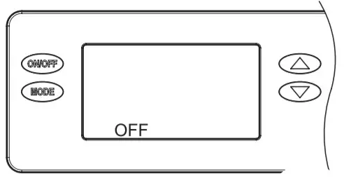
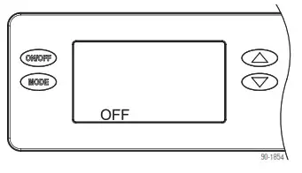
- The onboard control screen should display OFF.
 NOTE: If the display backlight is not on, the first button press (any button) will only turn on the backlight.Press the button a second time to achieve function.
 - Hold the MODE button on the onboard control for 3 seconds to enter the Installer Set-up Menu.
- Navigate through the following screens to set up the dehumidifier for the installed application.Use the UP or DOWN arrows to select items and use MODE to switch to the next set-up option.To exit the installer set-up, all options must be scrolled through using the MODE button.
- After the installer setup options have been completed, DONE will blink for 3 seconds, and the control will return to the OFF screen.
 NOTE: If the display backlight is not on, the first button press (any button) will only turn on the backlight.Press the button a second time to achieve function.
REMOTE CONTROL – CRAWL SPACE
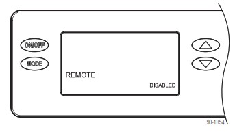 |
If not installed in a crawl space with Model 76 remote control, press MODE to go to the VENT screen selections |
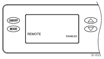 |
If installing in a crawl space with remote control, Enable and press MODE. The installer set-up is complete, proceed to SYSTEM CHECK on page 7.NOTE: Air Cycling is not an option when Remote is enabled. |
VENTILATION / AIR CYCLING
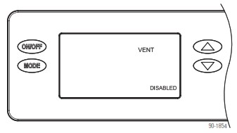 |
If not using the dehumidifier to periodically cycle air in the crawl space, press MODE to go to ZONE screen selections. |
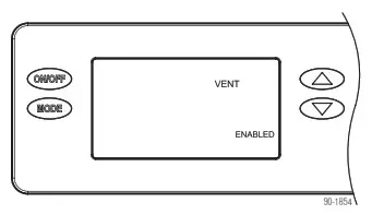 |
If using the dehumidifier for air cycling, Enable and press MODE. |
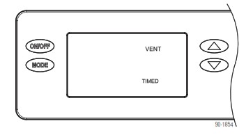 |
Press MODE at the VENT TIMED screen to go to the ventilation time selection screen. |
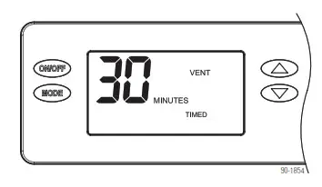 |
Press the UP or DOWN arrows to adjust the ventilation time per hour from 0 to 60 minutes. After selecting a time, press MODE. Press MODE through the ZONE, EXTERNAL, DEH w/AC, and RH offset screens. DONE will be displayed on the screen and Installer Set-up is complete. Proceed to SYSTEM CHECK. on page 7. |
SYSTEM CHECK
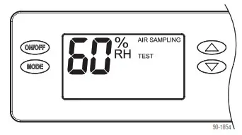 |
Press and hold the ON/OFF button and MODE buttons for 3 seconds.The measured humidity, AIR SAMPLING, and TEST will show on the display. |
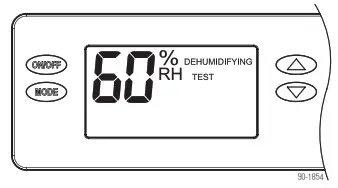 |
After three (3) minutes the dehumidifier compressor will turn on and DEHUMIDIFYING will replace AIR SAMPLING on the control screen. |
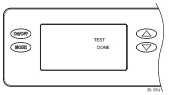 |
After one minute of compressor operation, all outputs will turn off, and DONE will blink for 3 secondsand then return to the OFF screen. |
 |
CRAWL SPACE USING THE DEHUMIDIFIER CONTROL
- Press the ON/OFF button to turn the dehumidifier control ON.The display will show the current setting, and the dehumidifier blower and HVAC blower (if wired to the HVAC system) will turn on to start sampling the air.The setting will be replaced by the measured humidity and “AIR SAMPLING” will show on the display.
- Use the UP or DOWN button to adjust the humidity setting as desired. The recommended initial setting is 59%.
- After three (3) minutes of sampling, the measured humidity will be compared to the setting:a . If the humidity is above the setting, the dehumidifier compressor turns on, and “AIR SAMPLING” will be replaced by “DEHUMIDIFYING”. The compressor remains on until the measured humidity falls 3% RH below the setting.b . If the measured humidity is below the setting, the blowers turn off and the display returns to showing the RH setting.
- The dehumidifier will sample again every 60 minutes, or at any time if the humidity setting is lowered.
CRAWL SPACE REMOTE CONTROL USING MODEL 76
- Press the ON/OFF button to turn the dehumidifier control ON. “REMOTE” will show on the display to indicate that the remote control is wired tothe dehumidifier .
- At Model 76, press the ON button; Model 76 will display the RH measured at the dehumidifier, and the dehumidifier blower will turnon to start sampling the air.
- Use the UP or DOWN button on Model 76 to adjust the dryness level as desired. The dryness levels are from 1 to 7, with 1 being the least dryand 7 being most dry; the recommended initial setting is 3.
- After three (3) minutes of sampling, the measured humidity will be compared to the setting:a . If the humidity is above the setting, the dehumidifier compressor turns on and “ON” flashes on the Model 76 display.b . If the measured humidity is below the setting, the dehumidifier blower turns off.
- The dehumidifier will sample again every 60 minutes, or at any time if the dryness level is increased.
START-UP
Your dehumidifier is equipped with two features that protect against unwanted energy consumption. Defrost is a normal operating mode that helps to prevent significant ice formation on the refrigeration system coil. The dehumidifier display will show “DEFROSTING” when operating in this mode. This mode can occur when there is not enough air moving through the dehumidifier or if the temperature and/or humidity of the incoming air is too low. The second protection feature is the E8 code. E8 on the dehumidifier display indicates that the air entering the dehumidifier is below 50°F or above 104°F, or the dew point of the incoming air is below 40°F. There would be a significant reduction in dehumidifier efficiency if the dehumidifier operated outside of these conditions. Low dew point conditions can be seen in some basements or crawl spaces and usually occur in the Winter and Spring months. The dehumidifier continues to monitor the incoming air and when the conditions are within the operating range, E8 will be removed from the display and dehumidification will begin as needed.
TROUBLESHOOTING
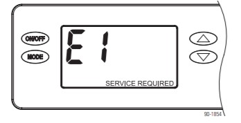
TABLE 1 – Diagnostic Codes
| Diagnostic code | Failure Mode | Action |
Reset |
| El | Internal Humidity or Temperature Sensor Open or Shorted | 1 . Cycle power to clear error code.2. Cycle power to clear error code.3. If error code reoccurs replace User Interface. Part No. 5475. | Cycle Power |
| E2 | High Refrigeration Pressure | I. Verify that the fan works and there is no blocked or restricted ductwork. 2. If the fault persists, call Technical Support. | Cycle Power |
| E3 | Model 76 Remote control Communication Loss | I. Check connections between Model 76 and the dehumidifier control board. Terminals should be fully inserted and secured in the control board and Model 76 control terminals.2. If connections are correct and secure. turn off the dehumidifier and remove the Model 76. Use a short section of 4-wire cable to reconnect the Model 76 to the control board. Turn the dehumidifier back on and increase the dryness level setting on Model 76. If the dehumidifier turns on, the problem is with the wiring between the dehumidifier and control.3. If the dehumidifier does not turn on, call Technical Support. | Self-Correcting |
| E4 | Insufficient Capacity | 1 Check the frost sensor connection at the power board. The terminal should be fully seated on the power board pins.2. Remove the side access panel and verify that the sensor is secured to the suction line.3. If the sensor is connected and secured to the refrigeration line proceed to the next step.4. Reset the fault by cycling power to the dehumidifier.5. Turn the humidity setting down (below room/home humidity level) to make a dehumidification call.6. Allow the fan and compressor to run for approximately 10-15 minutes and then enter diagnostic test mode by simultaneously pressing the UP ARROW and MODE buttons for 3 seconds. The LCD will display the temperature measured by the internal sensor while also displaying AIR SAMPLING and ON, the humidity measured by the internal sensor while also displaying %RH and ON., and the frost sensor temperature while also displaying ON. Scroll through these values and by using the UP/DOWN arrow buttons.7. Record values and call Technical Support. | Cycle Power |
| E5 | High-Temperature Thermistor Failure | 1. Check the high-temperature sensor connection at the power board. The terminal should be fully seated on the power board pins.2. Remove the side access panel and verify the sensor is not damaged and connected to the refrigeration line coming from the compressor.3. II the sensor is connected and secured to the refrigeration line, contact Technical Support. | Cycle Power |
| E6 | Low-Temperature Thermistor Failure | I. Check the low-temperature sensor connection at the power board.2. Remove the side access panel and verify the sensor is not damaged and connected to the suction line.3. If the sensor is connected and secured to the refrigeration line, contact Technical Support. | Cycle Power |
| E7 | float Switch Open | 1. Empty the condensate pan.2. Check the float switch connection at the control board.3. If not using a float switch, verify jumper is between float switch terminals on dehumidifier control board4. If the problem persists, replace the float switch. | Sell-Correcting |
| E8 | Inlet Air Temperature Out of Range 504 -104°F or dew point below 40°F | 1. Verify all ductwork is properly sealed.2. II no signs of leak points. contact Technical Support. | Sell-Correction |
TABLE 2 – Troubleshooting Guide
| Symptom | Possible Reason |
Troubleshooting Procedure |
| The dehumidifier does not turn on/run . | No power to the unit. |
|
| Dehrndther bonnet is running but with little or no airflow | Pressure drop inns dehumidifier is higher than° 4’w c |
|
| Dehumidifier blower isrunning but compressoris not. | Float smell open |
|
| Coil hosing |
|
|
| Inlet air temperature is outside of the 50°F – 104°F range or the dewpoint is below 40°F and there is a demand for dehumidification. |
|
|
| A dehumidifier is not draining properly. | Drain line blocked or unitnot level. |
|
| A dehumidifier isproducing hot air. | Normal function. |
|
SERVICE PARTS
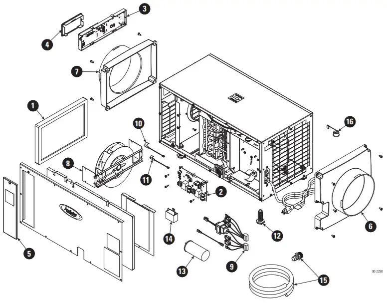
| No. | Part Description | Part No. |
| 1 | Filter, 8” x 11 .75” x 1” EZK | 5695 |
| 2 | Internal Control Board, Deh | 5444 |
| 3 | User Interface Assembly, Deh | 5445 |
| 4 | Wiring Access Door, AA Deh | 5446 |
| 5 | Door, Filter Access, AA Deh | 5696 |
| 6 | Outlet Duct Panel, Deh | 5698 |
| 7 | Inlet Duct Panel, AA Deh | 5699 |
| 8 | Fan with 6MFD Capacitor | 5694 |
| 9 | Wire Harness, Power, Deh | 5454 |
| 10 | Sensor, Low Temperature, Deh | 5455 |
| 11 | Sensor, High Temperature, Deh | 5456 |
| 12 | Leveling Foot, Deh | 5457 |
| 13 | Capacitor, 45MFD, 370VAC | 5458 |
| 14 | Capacitor, 6MFD, 250VAC | 5582 |
| 15 | Drain Tube + Fitting | 5692 |
| 16 | Compressor Overload Switch | 5697 |
| Not Shown | ||
| Condensate Pump with Tubing | 4856 |
AprilairePartners.comP.O. Box 1467Madison, WI 53701-1467800.334.6011 F: 608.257.4357Printed in the USA©2021 Aprilaire – Division of Research Products Corporation10015566 B2209249A 1.21
References
[xyz-ips snippet=”download-snippet”]