APT Middle Type Intelligent LCD Display User Manual
Tianjin APT Science and Technology Co., Ltd.
Display Specification
09/2018
Product: Middle Type Intelligent LCD DisplayModel: APT12LCD800S –UART -5SAbbreviation: 800S-UART
Client:Customer audit:
Supplier: Tianjin APT Science and Technology Co., Ltd.
1001, Building 5 HuaDing, No.1 HuaKe 3Road, Binhai hi-tech Industrial DevelopmentZone, Tianjin, ChinaTEL:+86 22 26345859FAX:+86 22 83719955
Email: [email protected]
Product Name
The Middle type intelligent LCD Display, model number as APT12LCD800S-UART-5S.
Supplier
Tianjin APT Science and Technology Co., Ltd.
Electrical Parameters
- 24V/36V/48V/52V battery output
- Rated operating current : 10mA
- Max operating current : 30mA
- Off leakage current < 1uA
- Output controller working current: 50mA
- Operating temperature : -30~70 ℃
- Storage temperature : -40~70 ℃
Dimensions & Materials
Display shell is ABS, transparent window is made with high strength Acrylic with stiffness equals as the tempered glass.
Dimensions: L90mm * W54mm * H13.3mm
Features
- Suitable for low temperature,Max -30 ℃.
- Ergonomic external button design, easy to operate.
- Speed display: AVG SPEED, MAX SPEED, AVERRAGE SPEED(Real-time).
- Kilometer/ Mile : Can be set as per customers’ habits.
- 9-level Assit : Up to users’ habit.
- Mileage indicator : Max trip distance(max 99,999.9)/ Odometer /Riding time
- Parameter settings: Multiple parameters can be set through computer USB port, including Assist level / Wheel diameter / Voltage / Speed limit, etc. For detailed, pls refer to separate computer parameter setting files.
LCD instructions
LCD display shown as below:
Function Description
Power On/Off
Press and hold Power button for 1 second, then display will work and controller power supply turn on. During the working mode, if press and hold Power button for 1 second, then display will stop and controller output will be cut off. If no further action to display within 5 minutes(could be set), display will cut off automatically and power output cut off.
Assist level selecting
Short press UP/DOWN button to change the assist level. Top assist level is 9, 1 is the lowest, when display turn on, automatically it will be level 1. 0 level is without any assistance.
Speed mode switch& Mileage mode switch
Short press POWER button can switch change the speed mode & mileage mode, data sequence is as:
Average Speed->Max Speed->Actual Speed->Single Trip->ODO-> Time.
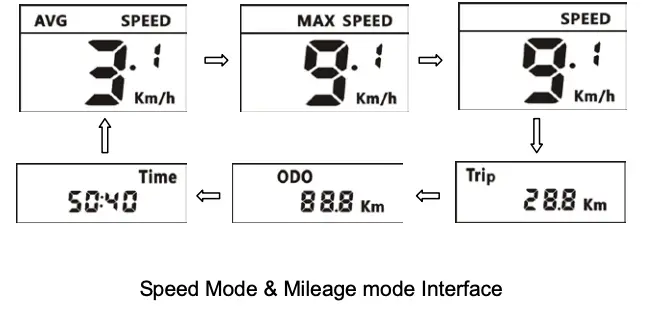
*If there is no operation for 5 seconds, display will return to Speed (Real-Time) display automatically.
Headlight/backlight On/Off
Press and hold UP button for 1 second , then headlight/backlight will turn on, if press UP button for 1 second again, then display backlight/headlight will turn off.
Battery Capacity Indication
5 bars in display to show battery capacity, if battery under voltage, then no bar in display, then battery needs to be charged immediately.
Parameter Setting
When system turn on, double press POWER button (press interval <0.3 second) can get into parameter setting state, under this, parameter could be set. And double press POWER button (press interval <0.3 second) to exit. In parameter setting state, when flashing, press UP/DOWN buttons to adjust parameters, short press POWER button to switch parameter items.
*The display will automatically exit parameters setting state if no operation for 10 seconds.
The order of parameters is as follows.
- Data cleanup:The location of speed displays symbol Cr,press UP/DOWN button to change no or yes.

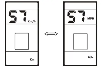
- Kilometer / Mile : The location of speed displays symbol S7, press UP/DOWN button to change between km/h / MPH (Km / Mile).
- Backlight brightness : The location of speed displays symbol bL1, press UP/DOWN button display symbol 1~5 to change the brightness of the backlight.1-darkest, 5-brightest.
- Auto off time : The location of speed displays symbol OFF, press UP/DOWN button to change the value from0 to 15, the number represent delay time (minutes) before display shutdown automatically.
- Wheel diameter: The location of speed displays symbol Wd, press UP/DOWN button to change between 16/18/20/22/24/26/27/28/700C/29, value represents the diameter of the wheel (inch). Wrong value for wheel diameter will cause speed & mileage abnormal.
- Voltage Setting : The location of speed displays symbol bU0, press UP/DOWN button to switch between 24V/36V/48V//52V/UbE, UbE means user-defined voltage setting, this parameter can be set through computer.
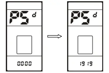
- Password/Speed Limit Setting : The location of speeds displays symbol PSd, require to input passwords, press UP/DOWN buttons to change the password value (0~9), short press POWER button to switch the password item, password is 4 digits, the default password is “1919“. Press POWER button when password adjustment is completed. Display will return to the Voltage set item if the password is incorrect. Correct password will enter the Speed Limit Setting item.
- Speed Limit Setting : The location of speed displays symbol SPL, the location of mileage displays speed limit value, the default value is 25km/h. Press UP/DOWN buttons to modify the value, the value can be set from 10 to 41km/h. Short press POWER button to enter the next item.The maximum speed is restricted by the motor and controller, probably couldn’t reach the setting value.
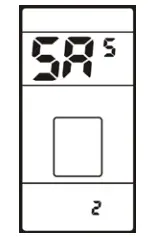
- Magnetic Pole numbers of speed sensor:The location of speed displays symbol HAL, the location of mileage displays magnetic pole number, press UP/DOWN buttons to modify the value. When setting finished, short press POWER to enter next setting.
- Direction of speed sensor: The location of speed displays symbol ASd, press UP/DOWN button rotate display symbol 0/1, 0 indicates forward, 1 indicates backward. When setting finished, short press POWER to enter next setting.
- Power Assistance Start Over Set Magnet Qty: The location of speed displays symbol SAS, the location of mileage shows pole number, press UP/DOWN buttons to modify the when power assistance start after certain qty of magnet. When setting finished, short press POWER to enter next setting.
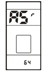
- Assistance level: The location of speed displays symbol ASr, the location of mileage shows assistance level value, press UP/DOWN buttons to modify the value. When setting finished, short press POWER to enter next setting.
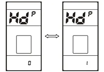
- Throttle set:The location of speed displays symbol HdP, press UP/DOWN button shows symbol 0~1 to change the throttle OFF or ON. When setting finished, short press POWER to enter next setting.
- Throttle 6KM set:The location of speed displays symbol Hd6, press UP/DOWN button shows symbol 0~1 to change the throttle 6km OFF or ON. When setting finished, short press POWER to enter next setting.
- Slow startup parameters: The location of speed displays symbol Sdr, the location of mileage displays value, press UP/DOWN button to modify the value.
- MAX Current Limit set: The location of speed displays symbol CUL, the location of mileage displays current limit value, the default value is 15A. Press UP/DOWN button to modify the value. When setting finished, short press POWER to enter next setting.
- Range of assist level setting: The location of speed displays symbol PAS, the location of mileage displays assist range, the default is UBE. Press UP/DOWN button to change the value from0-3 to UBE.
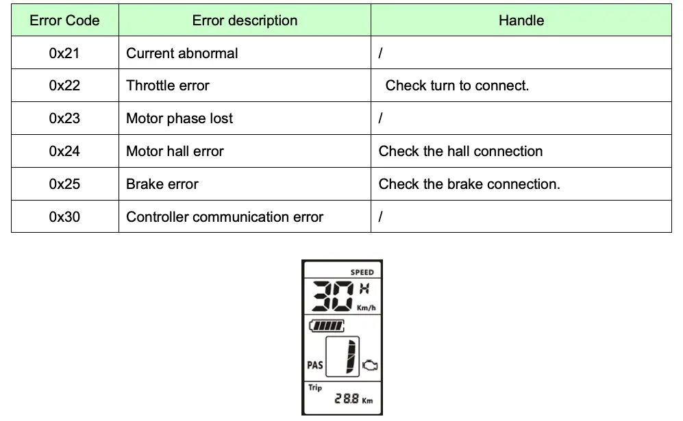
Error Code definition
800S-UART gives warning message when E-bike error, LCD display ![]() icon and the error code in speed position area, error code is from 21 E~30 E, the error codes definition as below table:
icon and the error code in speed position area, error code is from 21 E~30 E, the error codes definition as below table:
Assembly Instructions
Please pay attention to the screw’s torque value, damaged caused by excessive torque is not within the warranty.
There are 2 directions for the clamp installation, forward or backward.
Different assembly methods will need different cable length.
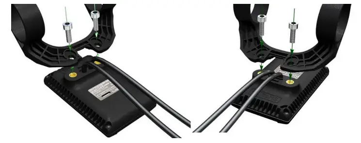
Clamps suit for 3 sizes of handlebar, 31.8mm, 25.4mm, 22.2mm, there are adaptor rings for 25.4mm and 22.2mm, adaptor ring must be assembled with the required directions, pay attention to the green arrow below.
Output Wire Instructions
- Red wire: Anode(24V/36V/48V/52V);
- Blue wire: Power cord to the controller;
- Black wire:GND;
- Green wire: RxD (controller -> display);
- Yellow wire: TxD (display -> controller);
Assistance Level Instructions
Assist level can be customized, the highest level is 9, common used assist level see the table below:
Certification
report this adCE / IP65 (water proof) / ROHS.
[xyz-ips snippet=”download-snippet”]