Aqua-Scope BVSZWE01 Ball Valve Servo
Quick-StartThis is a secure wireless Z-Wave Water Valve Motor Servo. For wireless operation it requires a Z-Wave capable gateway supporting European frequencies. To add the device, click the button three times in a row. Success is indicated by a green blinking LED. Complete the adding (inclusion) by following the instructions for the gateway. This device supports Z-Wave Smart Start. Please scan the QR Code on the device label before adding if your gateway supporting Smart Start.
Important safety information
Please read this manual carefully. Failure to follow the recommendations in this manual may be dangerous or may violate the law. The manufacturer, importer, distributor and seller shall not be liable for any loss or damage resulting from failure to comply with the instructions in this manual or any other material. Use this equipment only for its intended purpose. Follow the disposal instructions. Do not dispose of electronic equipment or batteries in a fire or near open heat sources.
What is Z-Wave?Z-Wave is the international wireless protocol for communication in the Smart Home. This device is suited for use in the region mentioned in the Quick-Start section.Z-Wave ensures a reliable communication by reconfirming every message (two-way communication) and every mains-powered node can act as a repeater for other nodes (meshed network) in case the receiver is not in direct wireless range of the transmitter.This device and every other certified Z-Wave device can be used together with any other certified Z-Wave device regardless of brand and origin as long as both are suited for the same frequency range.This device supports secure Z-Wave communication. It will communicate with other Z-Wave devices secure as long as the other device provides the same or a higher level of security. Otherwise it will automatically turn into a lower level of security to maintain backward compatibility.
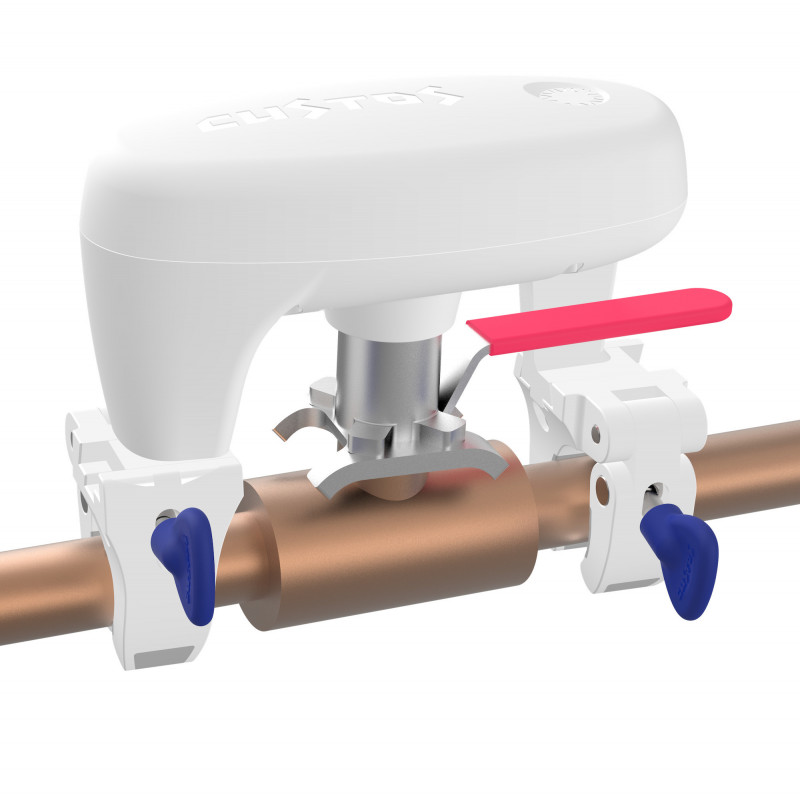
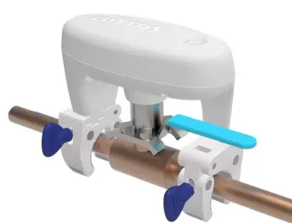
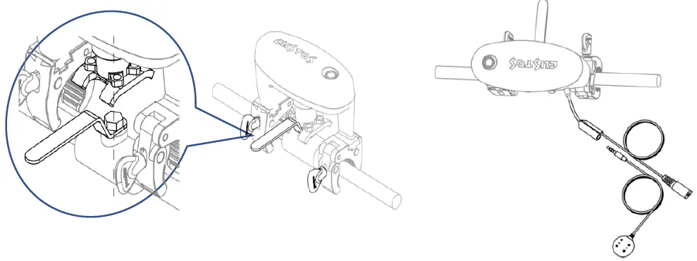
Product DescriptionThe BVS is a motor to retrofit existing and installed ball valves into smart water controlling devices. The motor is powered by a 12 V external power supply or – optionally – a battery block. The variable clamps allow mounting the device even in complex pipe installations, the patented motor coupling ensures easy installation and precise long-term operation. The device can operate in difficult environmental conditions, even submerged under water and allows directly connecting one additional local water sensor pad by cable.
The device can operate in two modes:
Stand-Alone: No further wireless connectivity is needed. A single click on the button opens and closes the valve. Clicking the button during open or close operation stops movement. The next click will continue the operation. Escaping water is detected by the external sensor pad and the valve it shut off accordingly. The button on the device allows clearing the alarm. Device in factory reset state operate in stand-alone mode without further configuration.
Z-Wave Network Mode: The device is added to a Z-Wave network as Z-Wave Binary Switch Device. Adding can be achieved using Smart Start or Classical Z-Wave Inclusion. All functions of the Stand-Alone mode remain active. Leakage or Temperature Alarms are forwarded to the Z-Wave Gateway and other Z-Wave device are able to control the motor.
CalibrationThe BSV is able to both measure the rotation angle and detect the end positions of the handle. It can therefore gently reach the end positions to avoid any friction and unneeded mechanical stress. Whenever the device is powered or repowered it will do a calibration run first. To start the calibration just hit the button once. You will witness some movements of the handle and after 10…20 seconds the device is ready to operate. Calibration requires that the BVS is mounted to a ball valve. The device will detect if no valve is present and stop calibration. In this case the operation of the handle (both by button and by wireless command) is disabled.
Prepare for Installation / ResetIn order to include (add) a Z-Wave device to a network it must be in factory default state. Please make sure to reset the device into factory default. You can do this by performing an Exclusion operation as described below in the manual. Every Z-Wave controller is able to perform this operation however it is recommended to use the primary controller of the previous network to make sure the very device is excluded properly from this network.
Reset to factory defaultThis device also allows to be reset without any involvement of a Z-Wave controller. This procedure should only be used when the primary controller is inoperable: Keep the button pressed for 10 seconds. Then click the button 5 times. The yellow LED will light up to confirm factory reset.
Installation
- Make sure the power is disconnected.
- Choose the right size of the fork according to the size of the valve handle.
- Make sure the two tightening knobs and the handle face opposite direction (handle must have clearance to move)
- Tighten clamps with hands while holding down the BVS.
- If needed – unplug the dust cover and connect the local Water Sensor Probe.
- Connect the DC Power Adapter to the power wire coming from the BVS and tighten the water seal.
- Plugin the power adaptor into 230 V power socket.

The BVS is designed for outdoor deployments. To prevent mis-operation by rain etc. users can disable the touch sense button. Once disabled the only accepted operation of the button is the reactivation. The operation of the touch sense button can also be enabled/disabled using Z-Wave configuration parameter #67. Enabling and disabling is performed by holding down the button for 3 seconds followed by three short clicks on the button.
Inclusion/ExclusionOn factory default the device does not belong to any Z-Wave network. The device needs to be added to an existing wireless network to communicate with the devices of this network. This process is also called Inclusion.Devices can also be removed from a network. This process is also called Exclusion. Both processes are initiated by the primary controller of the Z-Wave network. This controller is turned into inclusion respective exclusion mode. Inclusion and Exclusion is then performed doing a special manual action right on the device.AddingWhen using Smart start just scan the QR code on your device. When using classical Z-Wave inclusion, triple click the button. Success is indicated by a green LED blinking for one second plus two short beeps by the buzzerRemovingTriple click the button. Success is indicated by a green LED blinking for one second plus two short beeps by the buzzer.
Usage
Button UsageThe device has one single button with a three color Led built in. You can click on the button or keep the button pushed for some seconds. The BVS will help you counting the second by beeping every second.The device is designed for outdoor use and must prevent malfunction caused by water drops on the button. Hence, please push the button firmly (not too shy) even for clicking so that the touchless button will recognize your finger.
Local or remote open and close of the valveSingle click on the button starts the opening or closing action. Clicking the button during phase of movement stops the movement. Another click of the button resume operation. (Please note that first operation of valve after power on will always cause calibration. Refer to chapter ‘calibration’ for more details.)Z-Wave commands allow opening and closing of the valve using ON/OFF commands.
Local AlarmWhen the local sensor probe is attached it will detect water and cause an alarm. The alarm is reported to a Z-Wave controller – when in Z-Wave network mode – and it causes the valve to close. Blinking of red Led plus frequent sound of the buzzer indicate the alarm status. You can’t operate the valve anymore before alarm is cleared.To clear alarm perform two short clicks on the button (the buzzer will stop and the LED blinks green) and then keep the button pressed for two seconds (count two beeps). Triple green link of the LED confirms clearing the alarm.
Local SensorsThe device has built-in sensors that send sensor values to the Z-Wave Gateway when connected.
- Temperature Sensor Value
- Temperature Overheat Alarm (0x04-0x02, heat detected)
- External Sensor Probe
- Water Leak Alarm (0x05- 0x02 leak detected)
Quick trouble shootingHere are a few hints for network installation if things don’t work as expected.
- Make sure a device is in factory reset state before including. In doubt remove from network before adding to network again.
- If inclusion still fails, check if both devices use the same frequency.
- Remove all dead devices from associations. Otherwise you will see severe delays.
- Never use sleeping battery devices without a central controller.
- Do not poll FLIRS devices.
- Make sure to have enough mains powered device to benefit from the meshing.
Association – one device controls other devicesZ-Wave devices control other Z-Wave devices. The relationship between one device controlling another device is called association. In order to control a different device, the controlling device needs to maintain a list of devices that will receive controlling commands. These lists are called association groups and they are always related to certain events (e.g. button pressed, sensor triggers, …). In case of the event, all devices stored in the respective association group will receive the same wireless command wireless command, typically a ‘Basic Set’ Command.Association Groups:
| Number | Max Nodes | Description |
| 1 | 5 | Lifeline. All alarms and status information that shall be sent to the gateway |
| 2 | 5 | Switch Devices when Water Valve is operated (either local or by sensor o by wireless command) |
| 3 | 5 | Switch Devices when water leak was detected |
| 4 | 5 | Switch Devices when temperature raise above threshold |
| 5 | 5 | Switch Devices when temperature falls below threshold |
Configuration Parameters
Z-Wave products are supposed to work out of the box after inclusion, however certain configuration can adapt the function better to user needs or unlock further enhanced features. IMPORTANT: Controllers may only allow configuring signed values. In order to set values in the range 128 … 255 the value sent in the application shall be the desired value minus 256. For example: To set a parameter to 200 it may be needed to set a value of 200 minus 256 = minus 56. In case of a 2 byte value the same logic applies: Values greater than 32768 may needed to be given as negative values too.
Parameter 17: Water Valve Report ValueThis parameter defines how the water valve position is reported.Size: 1 byte, Default Value: 1
| Value | Description |
| 0 | Normal |
| 1 | Reversed |
Parameter 18: Command Sent into Association Group 2 on ONDefines what BASIC command Value to send into Association Group 2Size: 1 byte, Default Value: 1
| Value | Description |
| 0 | Disabled |
| 1 | Enabled Basic On (0xff) |
| 2 | Enabled, Basic Off (0x00) |
Parameter 19: Command Sent into Association Group 2 on OFFDefines what BASIC command Value to send into Association Group 2Size: 1 byte, Default Value: 2
| Value | Description |
| 0 | Disabled |
| 1 | Enabled Basic On (0xff) |
| 2 | Enabled, Basic Off (0x00) |
Parameter 33: Temperature Sensor ReportDefines if and how a temperature value is reported.Size: 1 byte, Default Value: 2
| Value | Description |
| 0 | Disabled |
| 1 | Report in Celsius |
| 2 | Report in Fahrenheit |
Parameter 34: Temperature Sensor Report ThresholdDefines the change in temperature value to cause unsolicited sending of an report.Size: 2 byte, Default Value: 0001
| Value | Description |
| 0x00-0xff | Value in Celsius (Example: 0x02 = 2 °C) |
| 0x100-
0x1ff |
Value in Fahrenheit (Example: 0x102 = 2 °F) |
Parameter 35: Temperature Sensor Report OffsetDefines a temperature offset for the reported temperature. This parameter can be used to compensate for certain temperature deviations.Size: 2 byte, Default Value: 0
| Value | Description |
| 0x00-0xff | Positive Deviation in Celsius (e.g. 0x02 = +2 °C) |
| 0x1000-
0x10ff |
Negative Deviation in Celsius (e.g. 0x02 = -2 °C) |
| 0x0100-
0x01ff |
Positive Deviation in Fahrenheit (e.g. 0x02 = +2 °F) |
| 0x1100-
0x11ff |
Negative Deviation in Fahrenheit (e.g. 0x02 = -2 °F) |
Parameter 36: Temperature Overheat TriggerSets the temperature to trigger and overheat alarm andSize: 2 byte, Default Value: 40 / 104
| Value | Description |
| 0x00-0xff | Value in Celsius (example: 0x02 = 2 °C) |
| 0x100-
0x1ff |
Value in Fahrenheit (Example: 0x102 = 2 °F) |
Parameter 37: Temperature Overhead Reset Trigger ValueSets the temperature to reset the overheat alarm andSize: 2 byte, Default Value: 40 / 104
| Value | Description |
| 0x00-0xff | Value in Celsius (Example: 0x02 = 2 °C) |
| 0x100-
0x1ff |
Value in Fahrenheit (Example: 0x102 = 2 °F) |
Parameter 38: Temperature Overhead Action ValueDefines what BASIC command Value to send into Association Group 4Size: 1 byte, Default Value: 0
| Value | Description |
| 0 | Disabled |
| 1 | Enabled Basic On (0xff) |
| 2 | Enabled, Basic Off (0x00) |
Parameter 39: Temperature Overhead Action Reset ValueDefines what BASIC command Value to send into Association Group 4Size: 1 byte, Default Value: 0
| Value | Description |
| 0 | Disabled |
| 1 | Enabled Basic On (0xff) |
| 2 | Enabled, Basic Off (0x00) |
Parameter 40: Freeze Trigger ValueSets the temperature threshold to cause a freeze alarmSize: 2 byte, Default Value: 0
| Value | Description |
| 0x00-0xff | Value in Celsius (Example: 0x02 = 2 °C) |
| 0x100-
0x1ff |
Value in Fahrenheit (Example: 0x102 = 2 °F) |
Parameter 41: Freeze Trigger Reset ValueSets the temperature threshold to reset a freeze alarmSize: 2 byte, Default Value: 40 / 104
| Value | Description |
| 0x00-0xff | Value in Celsius (Example: 0x02 = 2 °C) |
| 0x100-
0x1ff |
Value in Fahrenheit (Example: 0x102 = 2 °F) |
Parameter 42: Freeze Valve ActionThis parameter defines If detected freezing shall close the valveSize: 1 byte, Default Value: 1
| Value | Description |
| 0 | Disabled |
| 1 | Enabled |
Parameter 43: Freeze Association Action CommandDefines what BASIC command Value to send into Association Group 5Size: 1 byte, Default Value: 0
| Value | Description |
| 0 | Disabled |
| 1 | Enabled Basic On (0xff) |
| 2 | Enabled, Basic Off (0x00) |
Parameter 44: Freeze Association Reset CommandDefines what BASIC command Value to send into Association Group 5Size: 1 byte, Default Value: 0
| Value | Description |
| 0 | Disabled |
| 1 | Enabled Basic On (0xff) |
| 2 | Enabled, Basic Off (0x00) |
Parameter 49: Leak Detection Command ValueDefines what BASIC command Value to send into Association Group 3Size: 1 byte, Default Value: 1
| Value | Description |
| 0 | Disabled |
| 1 | Enabled Basic On (0xff) |
| 2 | Enabled, Basic Off (0x00) |
Parameter 50: Leak Detection Reset Command ValueDefines what BASIC command Value to send into Association Group 3Size: 1 byte, Default Value: 2
| Value | Description |
| 0 | Disabled |
| 1 | Enabled Basic On (0xff) |
| 2 | Enabled, Basic Off (0x00) |
Parameter 51: Water Leak Detection Valve ControlDefines if the valve shall be closed when a water leak alarm accursSize: 1 byte, Default Value: 1
| Value | Description |
| 0 | Disabled |
| 1 | Enabled |
Parameter 65: Buzzer enableDefines if built-in buzzer shall be activeSize: 1 byte, Default Value: 1
| Value | Description |
| 0 | Disabled |
| 1 | Enabled |
Parameter 66: LED Brightness LevelDefines the brightness level of LED in %Size: 1 byte, Default Value: 0x50
| Value | Description |
| 0-100 | Brightness level |
Parameter 67: Touch Sensor Key LockDefines if touch button is activeSize: 1 byte, Default Value: 1
| Value | Description |
| 0 | Disabled |
| 1 | Enabled |
Parameter 81: NotificationsDefines which notifications are activeSize: 1 byte, Default Value: 0x0d
| Bit | Description |
| 0 | Water Valve Report |
| 1 | Overheat Report |
| 2 | Freeze Report |
| 3 | Water Leak |
Technical Data
| Parameter | Value |
| Model No. | BVS-ZWU (US) / BVS-ZWE (EU) |
| Dimensions | 14.8 x 9.6 x 13.3mm |
| Weight | BVS Unit: 603g |
| Body Color | White |
| Knob Color | Blue |
| Waterproof and Dustproof | IP66 level / Outdoor deployment |
| Usage | For Indoor and Outdoor Water Valve On/Off |
| Operation Temperature | 14~122° F (-10 ~ +50°C) |
| Relative Humidity | 8% ~ 80% |
| Parameter | Value |
| Z-Wave Module | ZGM130S037HGN1 |
| Z-Wave RF Distance | 40m (Indoor) / 140m (Outdoor) |
| Region Frequency | EU: 868.42 & 869.85MHz |
| Motor Torque Power | Adaptive torque output max: 6n.m |
| Water Leak Sensor | Local Water Leak Sensor Probe |
| Temperature Sensor | Built-in MCP9700x, Range from -40°C to +125°C / (-40°F to +257°F) |
| Action Button | Touch Sense Button x 1 |
| LED Indicator | 3 colors LED. (Green, Yellow & Red) |
| Sound Indicator | Buzzer (Max. 85dB) |
| Power Supply | AC-DC: AC (110V 60Hz / 220V 50Hz); DC (12V / 1A) |
| Power Consumption | Standby: ~10mA @ 12VDC = 0.12W
Full Operation: Max ~700mA @ 12VDC = 8.4W |
| Parameter | Value |
| Wireless Technology | Z-Wave |
| Z-Wave Certification Type | Z-Wave Plus v2 Certification |
| Z-Wave SDK Version | v7.13.2 |
| Z-Wave Library | Enhanced 232 Slave |
| Z-Wave Role Type | Always On Slave |
| Device Type | Binary Switch |
| Generic Device Type | Switch Binary |
| Specific Device Type | Valve Open Close |
| Security Class | Non-Security, S0, S2 Unauthenticated and S2 Authenticated |
| SmartStart | Support: After powering on, SmartStart is auto activated if it’s out of Z-Wave network
when power on |
| Firmware Update | Support: Firmware upgrade support via RF, “Over The Air (OTA)” |
| Z-Wave Product ID | 0270.0001.000A |
| Power Down Memory | Support: Valve ON/OFF and Leak Alarm support suddenly power cut and restore
previous status |
Support and Contact
Should you encounter any problem, please give us an opportunity to address it before returning this product. Please check our website www.aqua-scope.com and particularly the support section for answers and help. You can also send a message to [email protected] While the information in this manual has been compiled with great care, it may not be deemed an assurance of product characteristics. Aqua-Scope shall be liable only to the degree specified in the terms of sale and delivery. The reproduction and distribution of the documentation and software supplied with this product and the use of its contents is subject to written authorization from Aqua-Scope. We reserve the right to make any alterations that arise as the result of technical development.Phone: +372 (0) 6248002Email: [email protected]Web: www.aqua-scope.com
Declaration of Conformity
Aqua-Scope Technology OÜ, Sakala 7-2, 10141 Tallinn, Republic of Estonia, The radio emitting device works on frequency 868…849 MHz with output power of 4 dBm. (2.5 mW)
 report this ad
Disposal Guidelines:Do not dispose of electrical appliances as unsorted municipal waste, use separate collection facilities. Contact your local government for information regarding the collection systems available. If electrical appliances are disposed of in landfills or dumps, hazardous substances can leak into the groundwater and get into the food chain, damaging health and well-being.![]()
References
[xyz-ips snippet=”download-snippet”]