AQUALISA iSys Digital Remote Control Installation Guide

Components


Literature not shown
Important information
The iSys Digital remote control is a remote button which provides a secondary method of ‘Start/stop’ for iSys Digital shower systems. When used with the iSys Digital diverter system, the remote can operate each outlet by pushing and holding the ‘Start/stop’ button for a few seconds as required. The remote control may be sited inside the showering area, as long as it is not subjected to continuous spray, or it can be sited outside the showering area – up to 10 metres from the Digital processor.
The iSys Digital remote control is not suitable for use with any other Aqualisa Digital product range.
THIS PRODUCT MUST BE INSTALLED BY A COMPETENT PERSON IN ACCORDANCE WITH ALL RELEVANT CURRENT WATER AND ELECTRICAL SUPPLY REGULATIONS.
ALL SHOWERS REQUIRING AN ELECTRICAL CONNECTION MUST BE INSTALLED BY A QUALIFIED PERSON FOLLOWING THE LATEST REVISION OF BS7671 (WIRING REGULATIONS) AND CERTIFIED TO CURRENT BUILDING REGULATIONS.
This product is suitable for domestic use only.This product is supplied complete with a 2 year guarantee.
Installation instructions
iSys Digital remote control
In addition to the guide below it is essential that the written instructions below are read and understood and that you have all the necessary components (shown overleaf) before commencing installation. Failure to install the product in accordance with these instructions may adversely affect the warranty terms and conditions. Do not undertake any part of this installation unless you are competent to do so. Prior to starting, ensure that you are familiar with the necessary plumbing regulations required to install the product correctly and safely.
THE DIGITAL PROCESSOR MUST BE ISOLATED FROM THE MAINS POWER SUPPLY PRIOR TO INSTALLING THE ISYS DIGITAL REMOTE CONTROL.
For use with single outlet iSys Digital shower systems
IF FITTING THIS PRODUCT WITH AN ISYS DIGITAL SINGLE OUTLET SHOWER SYSTEM, PLEASE FOLLOW THE FITTING INSTRUCTIONS BELOW.
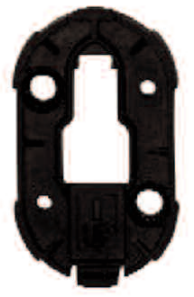
- Using the back plate as a template, mark the position of the fixing screws and a Ø16mm hole for the data cable entry point. The cable entry point should be made in the top right hand corner of the back plate recess, to ensure the two holes are kept separate.

- Prepare suitable wall fixings to accommodate no. 8 non-rusting 2 countersunk head screws of a suitable length (not included).
- Prepare a suitable route and install the 10m low voltage data cable leaving a working end of at least 70mm including the connector plug. The end of the data cable closest to the processor should terminate at a maximum of 500mm from the processor to allow for connection to the data cable connection block.DATA CABLES MUST BE PROTECTED BY SUITABLE SHEATHING OR CONDUIT IN THE EVENT OF SERVICING AND MAINTENANCE.
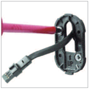
- Pull the data cable through before securing the back plate to the wall using suitable no. 8 non rusting countersunk screws.
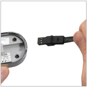
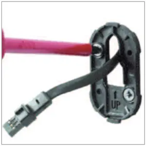
- Push the data cable plug into the back of the button fully home to ensure a water tight seal making sure the seal is no longer visible.
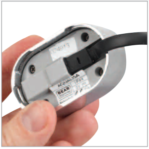
- Locate the slot at the top of the button assembly, onto the locating peg at the top of the back plate assembly, and lower the button into position.
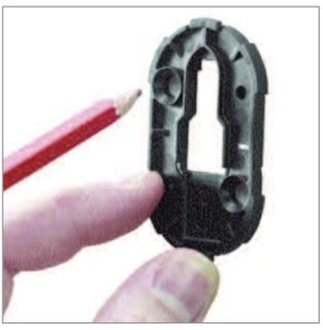
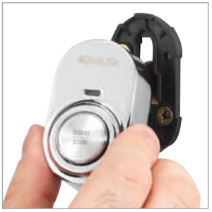
- Secure the button to the back plate by carefully but firmly pushing the button assembly onto the locking clip at the bottom of the back plate.To release the button, insert a small flat bladed screw driver into the small slot at the bottom of the button assembly, to release the locking clip, taking care to avoid damaging the plated surface. Carefully lift the button out and up off of the back plate top locating peg.BEFORE ANY ELECTRICAL ADJUSTMENT IS ATTEMPTED, THE ELECTRICITY SUPPLY MUST BE TURNED OFF AT THE MAINS SWITCH. ELECTRICAL INSTALLATION MAY ONLY BE CARRIED OUT BY A QUALIFIED PERSON.
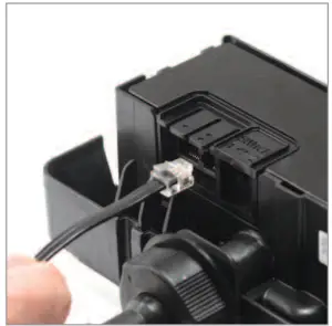
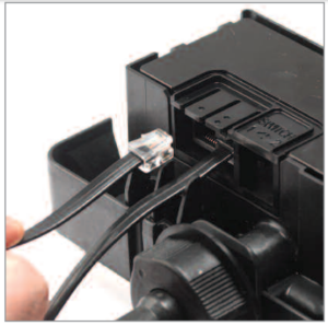
- The Digital processor features a secondary data cable socket next to the main data cable connection for use with the Digital remote control secondary ‘Start/stop’ button. Carefully snap and remove the entry pillar and connect the cable to the socket as shown.
- Prior to commissioning the iSys Digital remote control following the procedure overleaf, please refer to the installation instructions provided with the main iSys Digital product to complete the installation of the Digital processor.

 BEFORE ANY ELECTRICAL ADJUSTMENT IS ATTEMPTED, THE ELECTRICITY SUPPLY MUST BE TURNED OFF AT THE MAINS SWITCH. ELECTRICAL INSTALLATION MAY ONLY BE CARRIED OUT BY A QUALIFIED PERSON.
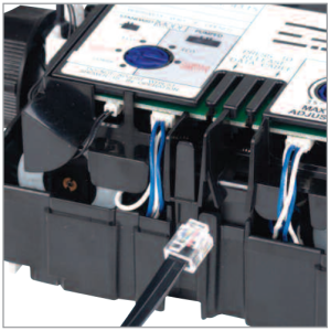
For use with iSys Digital Divert systems
IF FITTING THIS PRODUCT WITH AN ISYS DIGITAL DIVERT SHOWER SYSTEM, PLEASE FOLLOW THE FITTING INSTRUCTIONS BELOW.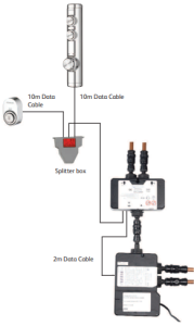
- Using the back plate as a template, mark the position of the fixing screws and a Ø16mm hole for the data cable entry point. The cable entry point should be made in the top right hand corner of the back plate recess, to ensure the two holes are kept separate.
- Prepare suitable wall fixings to accommodate no. 8 non-rusting countersunk head screws of a suitable length (not included).
- Prepare a suitable route and install the 10m low voltage data cable leaving a working end of at least 70mm including the connector plug. The end of the data cable closest to the splitter junction box should terminate at a maximum of 500mm from the splitter junction box to allow for connection to the data cable connection block.DATA CABLES MUST BE PROTECTED BY SUITABLE SHEATHING OR CONDUIT IN THE EVENT OF SERVICING AND MAINTENANCE.
- Pull the data cable through before securing the back plate to the wall using suitable no. 8 non rusting countersunk screws.
- Push the data cable plug into the back of the button fully home to ensure a water tight seal making sure the seal is no longer visible.
- Locate the slot at the top of the button assembly, onto the locating peg at the top of the back plate assembly, and lower the button into position.
- Secure the button to the back plate by carefully but firmly pushing the button assembly onto the locking clip at the bottom of the back plate.To release the button, insert a small flat bladed screw driver into the small slot at the bottom of the button assembly, to release the locking clip, taking care to avoid damaging the plated surface. Carefully lift the button out and up off of the back plate toplocating peg.To release the button, insert a small flat bladed screw driver into the small slot at the bottom of the button assembly, to release the locking clip, taking care to avoid damaging the plated surface. Carefully lift the button out and up off of the back plate top locating peg.
- Plug one end of the 2m data cable (supplied with the Digital Diverter) into the open entry port of the main processor box.
- Plug the other end of the 2m data cable (supplied with the Digital Diverter) into port 2 on the Digital Diverter.
- Plug the end of the attached data cable feeding from the splitter box into port 1 of the Digital Diverter.
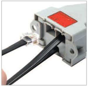
- Plug the end of the 10m low voltage data cable feeding from the main controller, as well as the end of the 10m low voltage data cable feeding from the remote button, into the two side by side entry ports on the splitter junction box as shown.PLEASE NOTE, THE 10M LOW VOLTAGE DATA CABLES CAN BE PLUGGED INTO EITHER OF THE SIDE BY SIDE ENTRY PORTS OF THE SPLITTER JUNCTION BOX, THIS WILL NOT AFFECT THE OPERATION OF THIS PRODUCT.
- Prior to commissioning the iSys Digital remote control following the procedure overleaf, please refer to the installation instructions provided with the main iSys Digital product to complete the installation of the Digital processor.iSys controllers are supplied with a temporary, clear protective film on the controls, please remove film once the product has been installed.


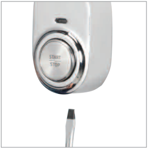
 To release the button, insert a small flat bladed screw driver into the small slot at the bottom of the button assembly, to release the locking clip, taking care to avoid damaging the plated surface. Carefully lift the button out and up off of the back plate top locating peg.
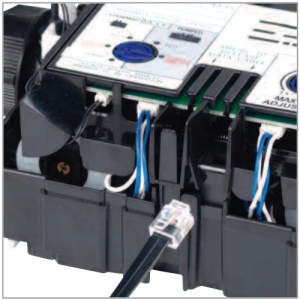

Aqualisa Products LimitedThe Flyer’s WayWesterham Kent TN16 1DECustomer helpline: 01959 560010Brochure Hotline: 0800 652 3669Website: www.aqualisa.co.ukEmail: [email protected]Republic of IrelandSales enquiries: 01-864-3363Service enquiries: 01-844-3212
Please note that calls may be recorded for training and quality purposesThe company reserves the right to alter, change or modify the product specifications without prior warning® Registered Trademark Aqualisa Products Limited
 report this ad
References
[xyz-ips snippet=”download-snippet”]