![]()
WIRED REMOTEINSTALLATIONGUIDE
IMPORTANT INFORMATION – ALL REMOTES
Safety informationThis appliance can be used by children aged from 3 years and above and persons with reduced physical, sensory or mental capabilities or lack of experience and knowledge if they have been given supervision or instruction concerning the use of the appliance in a safe way and understand the hazards involved.Children shall not play with the appliance.Cleaning and user maintenance shall not be made by children without supervision.These wired remotes provide a secondary method of ‘Start/Stop’ forVisage™ Smart and Aqualisa Smart Link™ shower systems. The wired remote may be sited inside the showering area, as long as it is not subjected to continuous spray, or it can be sited outside the showering area – up to 10 meters from the Aqualisa SmartValve ™ . IMPORTANT: CONTROLLERS AND REMOTES FROM DIFFERENT PRODUCT RANGES ARE NOT CROSS-COMPATIBLE.Contact the Aqualisa Customer Helpline for further information.THIS PRODUCT MUST BE INSTALLED BY A COMPETENT PERSON IN ACCORDANCE WITH ALL RELEVANT CURRENT WATER AND ELECTRICAL SUPPLY REGULATIONS.ALL PRODUCTS REQUIRING AN ELECTRICAL CONNECTION MUST BE INSTALLED BY A QUALIFIED PERSON FOLLOWING THE LATEST REVISION OF THE ELECTRICAL WIRING REGULATIONS, BOTH NATIONAL AND LOCAL, AND CERTIFIED TO CURRENT BUILDING REGULATIONS.
Cables that are chased into the wall must be protected by a suitably sized conduit or sheathing to allow for removal in the event of service and maintenance purposes. Failure to install this way may invalidate the warranty.Ensure that the conduit is run to avoid the wired remote fixing holes.Surface-mounted cables must also be protected by a suitable approved conduit, even in a loft, where there may be a risk of damage from vermin. The wired remote is supplied from a safe low voltage source. This product is suitable for domestic use only.The wired remote must not be installed in situations where the ambient temperature is likely to fall below 5ºC or rise above 40ºC.We do not recommend the use of wired remotes in steam therapy facilities.Aqualisa products are supplied complete with a 1-year guarantee that can be upgraded by registering the product with Aqualisa.See www.aqualisa.co.uk/guarantee for details.Please refer to the main installation guide’s Important Information section for further safety information.Declaration of conformityAqualisa Products Limited declares that the remote in conjunction with the Aqualisa SmartValve™, diverter, and main controller complies with the essential requirements and other relevant provisions of the Low Voltage Directive (2014/35/EU) and the EMC Directive (2014/30/EU).Continue overleaf for Visage™ Smart remote installation.
COMPONENTS AQUALISA SMART LINK ™
Before commencing installation, it is essential that the instructions below are read and understood and that you have all the necessary components. Prior to installation, ensure all additional guides supplied with this product are read and understood.Failure to install the product in accordance with these instructions may adversely affect the warranty terms and conditions. Do not undertake any part of this installation unless you are competent to do so. Prior to starting, ensure that you are familiar with the necessary plumbing and wiring regulations required to install the product correctly and safely. The Aqualisa SmartValve™ must be isolated from the mains power supply prior to installing the wired remote.
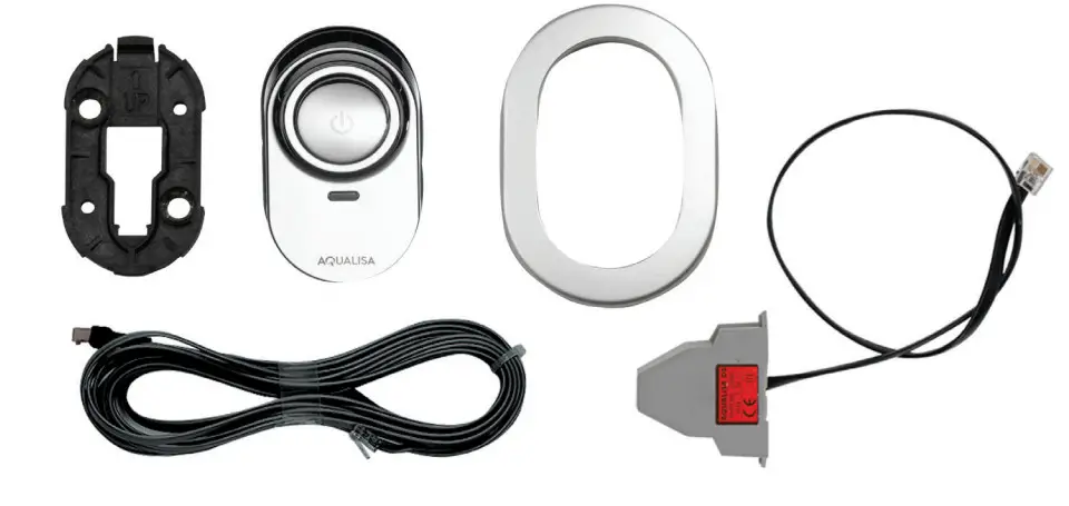
WIRED REMOTE COMPONENTS
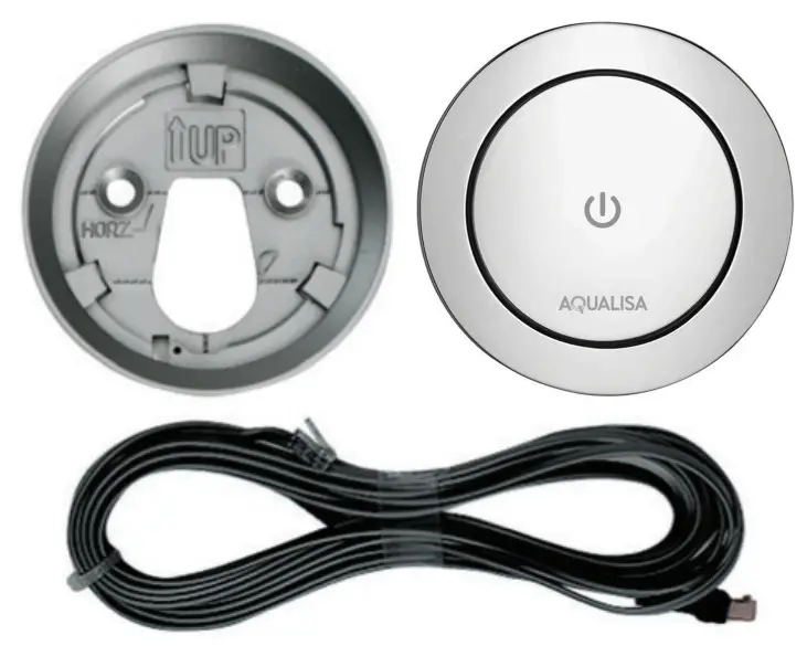
Aqualisa Smart Link™ components shown for illustrative purposes
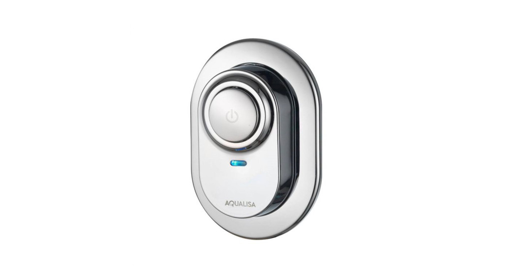
WIRED REMOTES

Aqualisa Smart Link™ shown for illustrative purposes
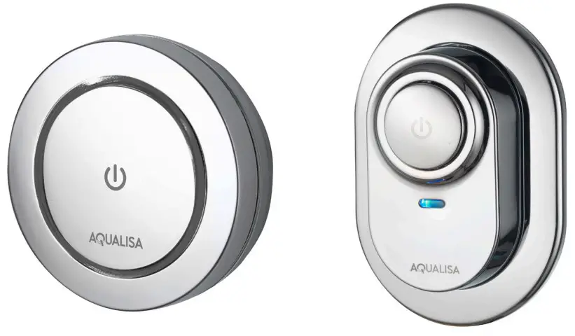
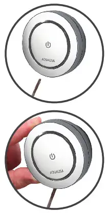
THERE ARE TWO VARIANTS OF AQUALISA SMART LINK™ REMOTES:![]() SINGLE OUTLET
SINGLE OUTLET![]() DUAL OUTLET (DIVERT)IMPORTANT: THESE ARE NOT CROSS-COMPATIBLE.
DUAL OUTLET (DIVERT)IMPORTANT: THESE ARE NOT CROSS-COMPATIBLE.
INSTALLATION OF AQUALISA SMART LINK ™ WIRED REMOTE
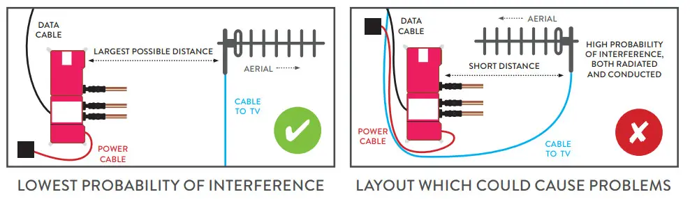
Digital TV InterferenceAlthough the Aqualisa SmartValve™ complies with all relevant EMC standards, if incorrectly sited, it may interfere with digital TV reception. Please follow the recommendations below to minimize this effect.See recommended layouts below.Images of Aqualisa SmartValve™ for illustration only, refer to the main installation guide for orientation.
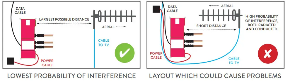
- Route cables separately, and as far apart from each other as possible.
- Aerial to point away from the Aqualisa SmartValve™.
- Ensure the distance between the Aqualisa SmartValve™ and the aerial is as large as possible.
Wiring Diagram – Single Outlet (Aqualisa Smart Link™)Aqualisa Smart Link™ is shown for illustrative purposes.
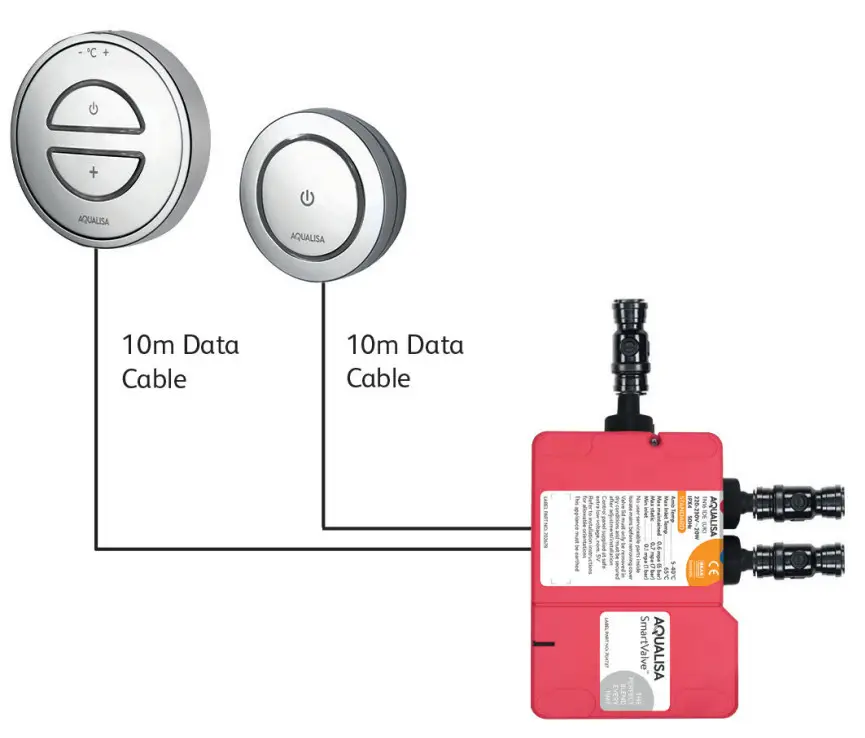
Cables must be run in conduit or trunking/sheathing.
Wiring Diagram – Dual Outlet (Divert) (Aqualisa Smart Link™)Aqualisa Smart Link™ is shown for illustrative purposes.
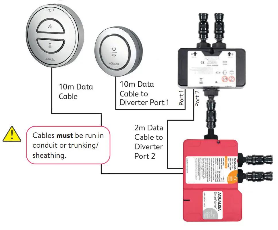
![]() N.B. The primary outlet is dictated by the “Switch mode” on the diverter. Refer to the Aqualisa SmartValve™ installation guide, sections: Diverter Outlet and Diverter Controller Matrix.
N.B. The primary outlet is dictated by the “Switch mode” on the diverter. Refer to the Aqualisa SmartValve™ installation guide, sections: Diverter Outlet and Diverter Controller Matrix.
- Using the backplate as a template, mark the position of the fixing screws and a Ø20mm hole for the data cable rear entry point. Prepare suitable wall fixings to accommodate no. 8 non-rusting countersunk head screws of a suitable length (not included).

- Prepare a suitable route and install the 10m low voltage data cable. On the AqualisaSmartValve™ or diverter side, allow sufficient length for plugging into the socket. On the wired remote side we recommend a minimum length of 70mm including the connector plug.Ensure the data cable is the correct way round as both ends differ in the type of connection used (transparent connector to the Aqualisa SmartValve™ or diverter). Data cables must be protected by suitable sheathing or conduit in the event of servicing and maintenance. Failure to install this way may invalidate the warranty. A cut-out is provided in the backplate to facilitate surface-sited cable entry if preferred.
- Apply a thin bead of silicone sealant in the mastic groove at the rear of the mounting plate and pull the data cable through before securing the back plate to the wall using suitable no. 8 non-rusting countersunk screws.
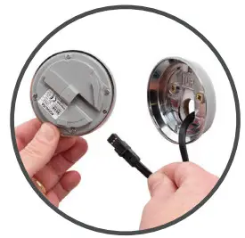
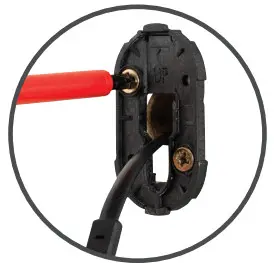
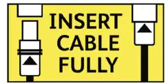
- Lining up the keyway, push the data cable plug into the back of the remote assembly, ensuring both rubber skirts are recessed into the connection (see diagram below), using a blunt flat-bladed screwdriver or similar tool if required. To make a watertight fitting, ensure the rubber seal is no longer visible.
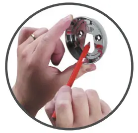
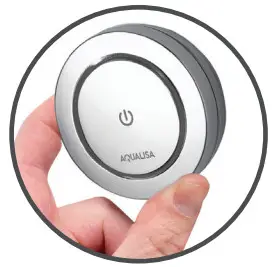
- Locate the remote assembly onto the backplate with the graphics in a diagonal position as illustrated. Rotate the remote clockwise so the graphics are in the horizontal position to lock the unit in place.To release the remote, insert a small flat-bladed screwdriver into the small opening at the 7 o’clock position to release the locking mechanism, and rotate the remote face anti-clockwise.Before any electrical adjustment is attempted, the electricity supply must be turned off at the mains switch. Electrical installation may only be carried out by a qualified person.
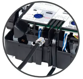
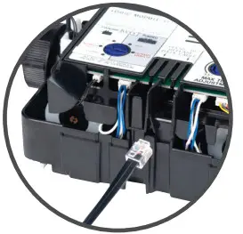
- For single outlet models, the Aqualisa SmartValve™ features a secondary data cable socket next to the main data cable connection for use with the remote. Carefully snap and remove the entry pillar and connect the cable into the socket as shown. For dual outlet (divert) models the transparent end of the wired remote cable plugs directly into port 1 of the diverter. This is indicated by the single dot.Aqualisa Smart Link™ dual outlet (divert) wired remotes can only be used with dual outlet (divert) products.Please refer to the Aqualisa SmartValve™ Installation Guide for further information.
- Prior to commissioning the wired remote, please refer to the installation instructions provided with the main product to complete the installation of the Aqualisa SmartValve™ and diverter (where supplied).

Commissioning1. Reconnect the power supply to the Aqualisa SmartValve™.2. Turn the shower system on using the main controller.The LED light ring will flash simultaneously with the remote light ring, until the desired temperature has been reached. When both LED lights to remain constant, turn the shower off using the main controller.3. Repeat the above process using the remote rather than the main controller ensuring the LED lights flash or remain constant simultaneously.
User guideSingle outlet system
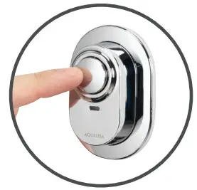
- Press the button on the wired remote to turn the shower on.
- The flashing to steady LED display advises when the temperature selected by the main controller has been reached.
- Turn the shower off either by pressing the main controller or remote button.

Dual outlet (divert) system
- Press the button on the wired remote to turn the shower on.
- The shower system will operate as determined by the outlet selected during the SmartValve™ installation – diverter controller matrix section.
- If required, push and hold the remote button for 3 seconds to stop the 1st outlet and start the 2nd outlet.
- The flashing to steady LED display advises when the temperature selected by the main controller has been reached.
- Turn the shower off either by pressing the main controller or remote button.

After installationRun through the wired remote operation with the user and hand them this guide, as well as the main installation and user guides, if applicable.Complete and post the guarantee card or register online at www.aqualisa.co.ukCleaning and maintenanceYour wired remote should be cleaned using only a soft cloth and washing up liquid.DO NOT USE ABRASIVE CLEANERSCleaning and maintenance should not be undertaken by children without supervision by a person responsible for their safety.
COMPONENTS VISAGE ™ SMART
Before commencing installation, it is essential that the instructions below are read and understood and that you have all the necessary components. Prior to installation, ensure all additional guides supplied with this product are read and understood.Failure to install the product in accordance with these instructions may adversely affect the warranty terms and conditions. Do not undertake any part of this installation unless you are competent to do so. Prior to starting, ensure that you are familiar with the necessary plumbing and wiring regulations required to install the product correctly and safely.The Aqualisa SmartValve™ must be isolated from the mains power supply prior to installing the wired remote.
VISAGE ™ SMART COMPONENTS
INSTALLATION OF VISAGE ™ SMART WIRED REMOTE
Digital TV InterferenceAlthough the Aqualisa SmartValve™ complies with all relevant EMC standards, if incorrectly sited, it may interfere with digital TV reception. Please follow the recommendations below to minimize this effect.See recommended layouts below.Images of Aqualisa SmartValve™ for illustration only, refer to the main installation guide for orientation.
- Route cables separately, and as far apart from each other as possible.
- Aerial to point away from the Aqualisa SmartValve™.
- Ensure the distance between the Aqualisa SmartValve™ and the aerial is as large as possible.
Wiring Diagram – Single Outlet Visage™ Smart
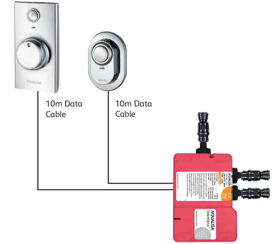
Cables must be run in conduit or trunking/sheathing.
Wiring Diagram – Dual Outlet (divert) Visage™ Smart
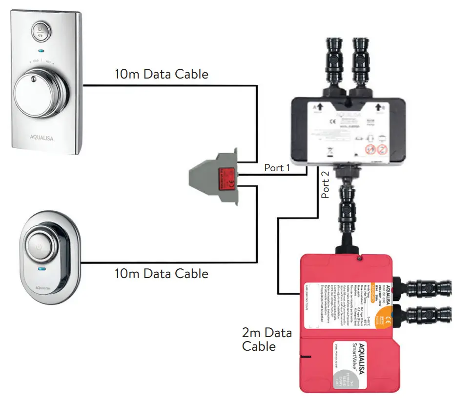
Cables must be run in conduit or trunking/sheathing.
 N.B. The primary outlet is dictated by the “Switch mode” on the diverter. Refer to the Aqualisa SmartValve™ installation guide, sections: Diverter Outlet and Diverter Primary Outlet Set Up.
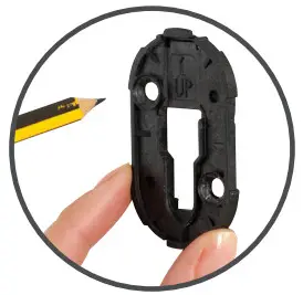
- Using the backplate as a template, mark the position of the fixing screws and a Ø16mm hole for the data cable entry point.The cable entry point should be made in the top right-hand corner of the backplate recess. This is to ensure sufficient distance is kept between the fixings and the cable entry hole.
- Prepare suitable wall fixings to accommodate no.8 non-rusting countersunk head screws of a suitable length (not included).
- Prepare a suitable route and install the 10m low voltage data cable. On the Aqualisa SmartValve™ or diverter side, allow sufficient length for plugging into the socket. On the wired remote side we recommend a minimum length of 70mm including the connector plug.Ensure the data cable is the correct way round as both ends differ in the type of connection used (transparent connector to the Aqualisa SmartValve™ or diverter). Data cables must be protected by suitable sheathing or conduit in the event of servicing and maintenance. Failure to install this way may invalidate the warranty.A cut-out is provided in the backplate to facilitate surface-sited cable entry if preferred.
- Pull the data cable through before securing the backplate to the wall using suitable no. 8 non-rusting countersunk screws.
- Lining up the keyway, push the data cable plug into the back of the remote assembly, ensuring both rubber skirts are recessed into the connection (see diagram below), using a blunt flat-bladed screwdriver or similar tool if required. To make a water-tight fitting, ensure the rubber seal is no longer visible.
- Locate the slot at the bottom of the button assembly, onto the locating peg at the bottom of the backplate assembly, and offer the button into position.
- Secure the button to the backplate by carefully but firmly pushing the button assembly onto the locking clip at the top of the backplate. To release the button, insert a small flat-bladed screwdriver into the slot at the top of the button assembly to release the locking clip, taking care to avoid damaging the plated surface. Carefully lift the button out and up off of the backplate bottom locating peg.
- Visage™ Smart comes with an optional wall plate. To secure this item, apply a thin bead of mastic to the groove at the rear of the wall plate. Place the wall plate into position and push flush to the finished wall surface, taking care to avoid any transfer of mastic from the wall plate onto the button assembly.WIRING SINGLE OUTLETBEFORE ANY ELECTRICAL ADJUSTMENT IS ATTEMPTED, THE ELECTRICITY SUPPLY MUST BE TURNED OFF AT THE MAIN SWITCH. ELECTRICAL INSTALLATION MAY ONLY BE CARRIED OUT BY A QUALIFIED PERSON.
- For single outlet models, the Aqualisa SmartValve™ features a secondary data cable socket next to the main data cable connection for use with the remote. Carefully snap and remove the entry pillar and connect the cable into the socket as shown.
- Prior to commissioning the wired remote, please refer to the installation instructions provided with the main product to complete the installation of the Aqualisa SmartValve™.WIRING DUAL OUTLET (DIVERT)BEFORE ANY ELECTRICAL ADJUSTMENT IS ATTEMPTED, THE ELECTRICITY SUPPLY MUST BE TURNED OFF AT THE MAIN SWITCH.ELECTRICAL INSTALLATION MAY ONLY BE CARRIED OUT BY A QUALIFIED PERSON.
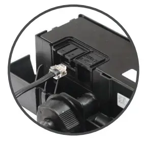
- Plug one end of the 2m data cable (supplied with the diverter) into the open entry port of the Aqualisa SmartValve™.
- Plug the other end of the 2m data cable (supplied with the diverter) into port 2 on the diverter, this is indicated by the double dot.
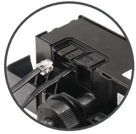
- Plugin the transparent connectors of both the 10m low voltage controller and remote cables into the splitter box (as shown). PLEASE NOTE, THE 10M LOW VOLTAGE DATA CABLES CAN BE PLUGGED INTO EITHER OF THE SIDE-BY-SIDE ENTRY PORTS OF THE SPLITTER JUNCTION BOX, THIS WILL NOT AFFECT THE OPERATION OF THIS PRODUCT.
- Plug the end of the data cable attached to the splitter box into port 1 of the digital diverter.
- Prior to commissioning the wired remote, please refer to the installation instructions provided with the main product to complete the installation of the Aqualisa SmartValve™.
 To release the button, insert a small flat-bladed screwdriver into the slot at the top of the button assembly to release the locking clip, taking care to avoid damaging the plated surface. Carefully lift the button out and up off of the backplate bottom locating peg.
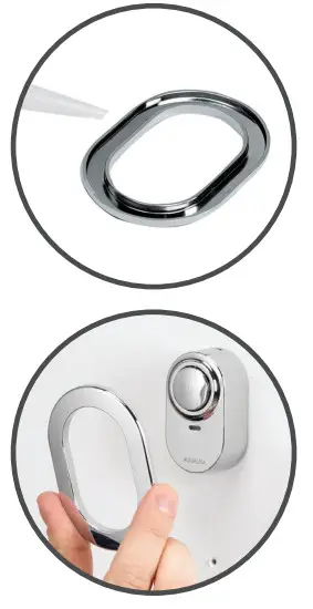 Place the wall plate into position and push flush to the finished wall surface, taking care to avoid any transfer of mastic from the wall plate onto the button assembly.WIRING SINGLE OUTLET
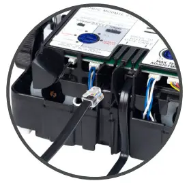
Commissioning
- Reconnect the power supply to the Aqualisa SmartValve™.
- Turn the shower system on using the main controller.The LED light will flash simultaneously with the remote control light until the desired temperature has been reached. When both LED lights to remain constant, turn the shower off using the main controller.
- Repeat the above process using the remote rather than the main controller ensuring the LED lights flash or remain constant simultaneously.
User guideSingle outlet system
- Press the button on the wired remote to turn the shower on.
- The flashing to steady LED display advises when the temperature selected by the main controller has been reached.
- Turn the shower off either by pressing the main controller or remote button.
Dual outlet (divert) system
- Press the button on the wired remote to turn the shower on.
- The shower system will operate as determined by the outlet selected during the diverter primary outlet set up (Visage™ Smart installation guide).
- If required, push and hold the remote button for 3 seconds to stop the 1st outlet and start the 2nd outlet.
- The flashing to steady LED display advises when the temperature selected by the main controller has been reached.
- Turn the shower off either by pressing the main controller or remote button.
After installationRun through the wired remote operation with the user and hand them this guide, as well as the main installation and user guides, if applicable.Complete and post the guarantee card or register online at www.aqualisa.co.uk Cleaning and maintenance Your wired remote should be cleaned using only a soft cloth and washing up liquid.DO NOT USE ABRASIVE CLEANERSCleaning and maintenance should not be undertaken by children without supervision by a person responsible for their safety.
Aqualisa Products LimitedThe Flyers WayWesterham Kent TN16 1DECustomer Helpline: 01959 560010Brochure Hotline: 0800 652 3669Website: www.aqualisa.co.ukEmail: [email protected]Republic of IrelandSales inquiries: 01-864-3363Service inquiries: 01-844-3212

Please note that calls may be recorded for training and quality purposes.The company reserves the right to alter, change or modify the product specifications without prior warning.™ Trademark of Aqualisa Products Limited.

report this ad
References
[xyz-ips snippet=”download-snippet”]