ARIES Mounting Brackets For Action Trac 3025175

WARNING: Improper electrical installation may result in personal injury. Unless you are familiar with the installation and handling of electrical systems, have this step performed by someone who has that familiarity.
Level of Difficulty
ModerateInstallation difficulty levels are based on time and effort involved and may vary depending on the installer level of expertise, condition of the vehicle and proper tools and equipment.
CAUTIONIf the step fails to actuate completely (open or closed), do not attempt to force the step open or close. Applying force in this condition will damage the product and void your warranty. Refer to the troubleshooting guide on the last page of the instruction manual to resolve potential issues.
NOTICE
- Visit www.ariesautomotive.com for a full-color copy of this instruction manual, as well as helpful videos, guides and much more!
- Before you begin installation, read all instructions thoroughly. Proper tools will improve the quality of installation and reduce the time required.
- ActionTrac™ Powered Running Boards feature a transportation mode cutoff switch to prevent battery drain. Switch to the off position if your vehicle is sitting idle for longer than one week.
- Periodic inspection of your product should be performed to ensure all wiring connections, hardware and / or components remain secure.
- To help prevent damage to the product or vehicle, refer to the specified torque specifications when securing hardware during the installation process.
Parts List
| 1 | Driver / left bracket A (1 notch) |
| 1 | Driver / left bracket B (2 notches) |
| 1 | Driver / left bracket C (3 notches) |
| 1 | Driver / left bracket D (4 notches) |
| 1 | Passenger / right bracket A (1 notch) |
| 1 | Passenger / right bracket B (2 notches) |
| 1 | Passenger / right bracket C (3 notches) |
| 1 | Passenger / right bracket D (4 notches) |
| 8 | T-Rails |
| 24 | Hex bolt, M8, black |
| 24 | Flat washer, M8, black |
| 8 | Lock washer, M8 |
| 16 | Serrated flange nut, M8 |
| 16 | Flat washer, 5/16” |
| 16 | Nylock nut, 5/16” |
| 4 | Door Sensor |
| 4 | Magnet |
| 2 | Alcohol wipe |
| 1 | Power switch |
| 1 | Circuit board |
| 1 | Anti-seize |
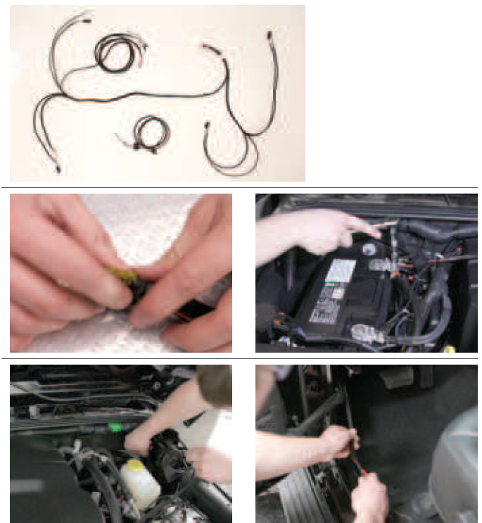
| 1 | Wire loom |
| 1 | Wiring harness, two-piece |
| 2 | LED light |
| 2 | LED light bracket |
| 2 | Rubber grommet, 1” |
| 4 | Double-sided foam tape, 3/4″ x 3/4″ |
| 4 | Double-sided tape, 3/4″ x 1″ |
| 4 | Double-sided tape, round |
| 8 | Cable tie, 8″ |
| 4 | Adhesive cable tie base |
| 1 | Mounting bracket for rocker switch |
Maintenance
No maintenance required on waterproof harness or water-resistant motors. If mud or dirt is built up on the steps, simply spray them off and let them air dry.Mild automotive detergent may be used to clean the product. Do not use dish detergent, abrasive cleaners, abrasive pads, wire brushes or other similar products that may damage the finish.
| Torque Specifications | |
| M8 bolt | 7 ft-lbs. |
| 5/16″ bolt | 7 ft-lbs. |
| Tools Required | |
| Ratchet | Socket set |
| Cable ties | Level |
Product Registration and Warranty
ARIES stands behind our products with industry-leading warranties. To get copies of the product warranties, register your purchase or provide feedback, visit: warranty.curtgroup.com/surveys
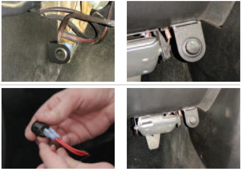
Step 1: Starting on the passenger side, locate the four mounting locations underneath the vehicle.Note: Each bracket is specific to a mounting location and side. Each bracket has notches cut into the vertical support – one notch is installed at the front mount location, four notches in the rear. Driver and passenger side are differentiated by the lower flange bend – these bends go toward the front of the vehicle.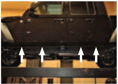
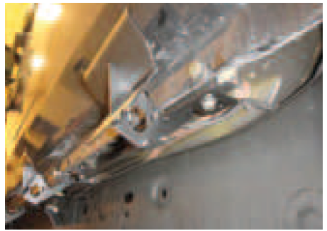
Step 2: Starting at the front driver-side mounting location, secure the mounting bracket in the two holes on the vehicle rocker panel using an M8 bolt, washer and flange nut.Once the bracket is attached, install one M8 bolt, lock washer and flat washer with anti-seize vertically through the slot in the bracket.Snug the hardware, but do not fully tighten.
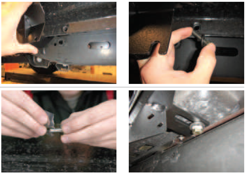
Step 3: Repeat step 2 for the remaining driver-side brackets.Repeat this entire process on the passenger side of the vehicle.
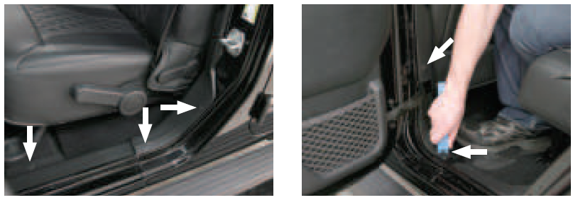
Step 4: Remove the fuse from the wiring harness before installing.Once the fuse is removed, take that section of the wiring harness and attach it to the battery. Route the opposite end of the harness through the firewall into the cab of the vehicle.Use a cable tie to secure the wiring harness in place once it is in the desired location.
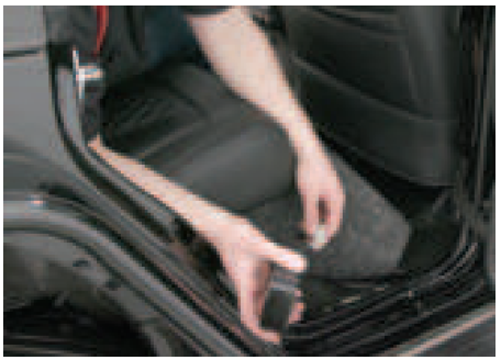
Step 5: Remove the fasteners securing the front and rear door trim panels on both sides of the vehicle. There are five clips on each side of the vehicle securing the trim panels, three for the front and two for the rear.Note: It may be easier to move the seats all the way back when removing the front trim panel and all the way forward when removing the rear trim panel.
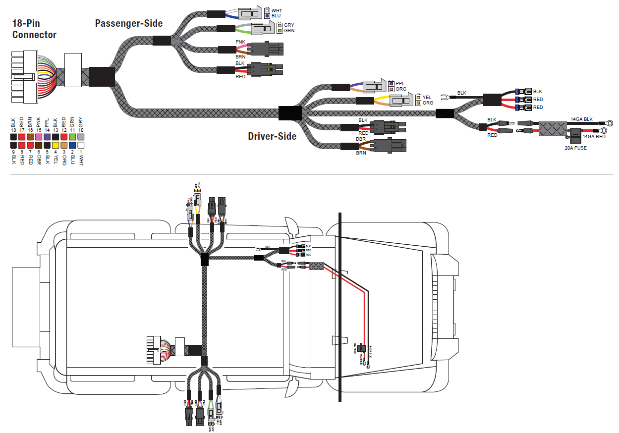
Step 6: Once the trim panels are removed, take the second section of wiring harness and route it under the carpet, through the vehicle, from the passenger-side rear to the desired location.Refer to the diagrams below.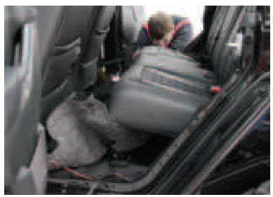
Wiring Locations
| Door sensor, rear | Purple / Orange |
| Door sensor, front | Yellow / Orange |
| LED light | Brown / Dark brown |
| Actuator | Black / Red |
| Door sensor, rear | White / Blue |
| Door sensor, front | Grey / Green |
| LED light | Pink / Brown |
| Actuator | Black / Red |
Step 7: On the driver side, take the power wire and sensor wire (orange / yellow) and route it to the front of the vehicle underneath the carpet.Take the driver-side rear actuator (red / black) and the LED light (brown / tan) and route it through the floor plug behind the driver seat.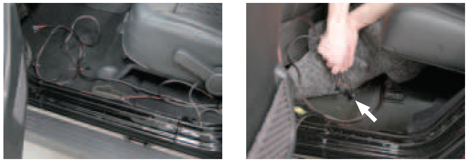
Step 8: On the passenger side, take the sensor wire (gray / green) and route it to the front of the vehicle underneath the carpet.Take the passenger-side rear actuator (red / black) and the LED light (pink / tan) and route it through the floor plug behind the passenger seat.
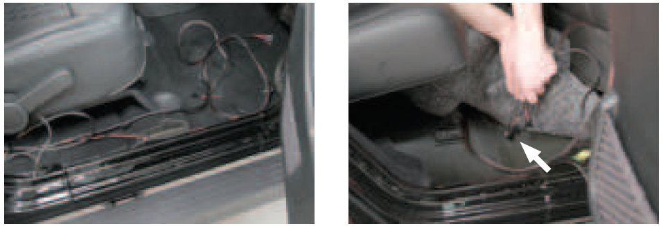
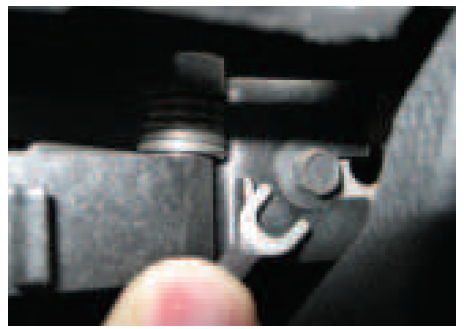
Step 9: With the rear wires inserted through the floor hole, cut a slot in the floor plug and re-insert it into the hole.
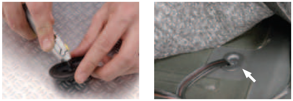
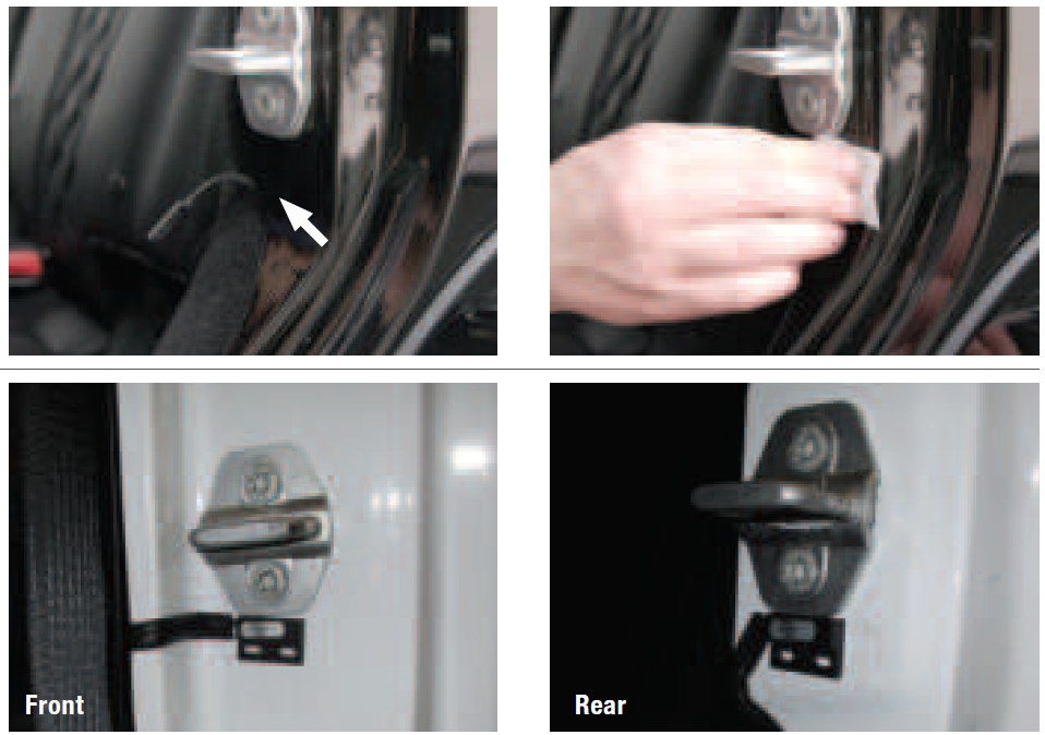
Step 10: Plug the door sensor into the wiring harness and route it up the door frame, under the carpet.Note: If installing a door delete switch, refer to part #3020000-INS at this time.Once the harness and sensor are routed to the desired locations, wipe the sensor and door with the provided alcohol wipe. Place the double-sided tape on the sensor and attach the sensor to the vehicle in the shown locations.Repeat this process for the other three doors.
NOTICE: Use of the door delete switch (part #3020000) requires manual operation of the boards. Failure to retract the boards when operating the vehicle could result in damage to the boards or vehicle.
Step 11: Temporarily position the supplied magnets on the doors in the recommended positions shown. Repeat this for the other three doors.
Note: On vehicles with aluminum body panels, non-marking tape may be used to temporarily secure the magnets.With the magnets in position complete the install of the ActionTrac™ running boards, power the system on, and test the boards by opening each door independently to ensure proper step function.Once all magnet locations are confirmed and the system is operating correctly, mark the magnet positions and permanently install using the round double sided adhesive.Note: If there are any issues with the step function refer to the ‘Troubleshooting’ section on the last page of this installation manual.
Step 12: Locate a spot to mount the power switch bracket. The bracket can be attached using either the 3/4″ double sided tape squares, screws (not provided), or by using a factory screw if one exists in a suitable location.
WARNING: If using screws confirm there are no wires behind the panel.NOTICE: Connect the two red wires to the silver terminals and the black wire to the bronze terminal.
Step 13: Locate a suitable location to connect the ground wire for the LED on the switch behind the dash panel.
Step 14: Once all wiring is installed, plug in the circuit board and place it underneath the carpet in a suitable location. Ensure the control module will not interfere with seat movement after install.Note: To complete the installation, refer to the manual included with your side bars / running boards.
TROUBLESHOOTING
| Condition | Possible Cause | Possible Solutions | Additional Information |
| Boards do not open when the door is opened | Power switch is off | Confirm that the main power switch is in the on position and has power. | — |
| Poor battery connection | Confirm the positive and negative connection on the battery are secure. | — | |
| Fuse is blown or removed | Confirm that the fuse is plugged in and not blown. | — | |
| Control module not connected | Confirm that the control module is plugged in. | — | |
| Board not connected | Confirm that the board connections are plugged in and secure. | — | |
| Door sensors not connected | Confirm that the door sensors are plugged in. | — | |
| Bad motor | Replace the board. | To check the motor function, apply 12 volts directly to the motor leads. If the board does not open, swap the leads and try again. If the board opens, the motor is good and swapping the leads back will cycle the board closed. | |
| Faulty control module | Replace the control module. | In rare cases, the programming of the control module may be faulty. Replace if the control module is receiving power
but the boards are not functioning properly. |
|
| Boards open with the front/rear door, but not the other | Door sensor disconnected | Confirm that the door sensor is plugged in. | — |
| Bad door sensor | Replace the sensor. | To check for a bad sensor, disconnect the sensor and check for continuity with a multi-meter. The sensor is normally a closed switch and should have continuity without the magnet present and should not have continuity when the magnet is placed near the sensor. | |
| Board is open and will not close | Magnet misalignment | Adjust the magnet position. | Disconnect both sensors and the board should close. Connect only one door sensor and test.
If the board closes, the alignment for that door is good. Connect the second sensor and repeat. |
| Bad door sensor | Replace the sensor. | To check for a bad sensor, disconnect the sensor and check for continuity with a multi-meter. The sensor is normally a closed switch and should have continuity without the magnet present and should not have continuity when the magnet is placed near the sensor. | |
|
Boards squeak when opening/closing |
Metal on metal contact | Apply graphite lubricant to all pivot points. | If excessive squeaking still occurs, check for worn out bushings or obvious areas of metal on metal contact. |
|
LED light does not turn on when the step is open |
LED not connected | Confirm that the LED connection is plugged in and secure. | — |
| Faulty LED | Inspect the LED and wiring harness for damage. | To test LED functionality, apply 12 volts directly to the LED. If the LED will not turn on
when directly connected, it will need to be replaced. |
|
| Boards function opposite to how they should (door open board closed, door closed board open) | Incorrect sensors | Replace the sensors. | To check for an incorrect sensor, disconnect the sensor and check for continuity with a multi-meter. The sensor is normally a closed switch and should have continuity without the magnet present and should not have continuity when the magnet is placed near the sensor. |
| Motor harness polarity reversed | Replace the board. | If sensors are confirmed to be correct (normally closed) and board still operates in reverse, the motor electrical harness may be reversed. | |
| After quick succession of cycling the boards
multiple times, the boards no longer open. |
A programed safety limit has been reached. | Using the main switch, power off the boards for 5-10 seconds and turn back on.
The boards should cycle when turned back on. |
The LED will flash 8 times when this issue occurs. |
| Boards do not open when both front and rear doors are opened simultaneously | Software limitation | Close the doors and open them individually. | A software limitation will prevent the boards from opening if both the front and rear door are opened simultaneously. Closing the doors and opening them one at a time will reset the board. |

References
[xyz-ips snippet=”download-snippet”]