
![]() Unvented water heater
Unvented water heater
![]() “Enactment of Directive 2012/19/EU governing electrical and electronic waste (WEEE)”The barred bin symbol on the appliance and its packaging indicate that the product must be scrapped separately from other waste at the end of its service life. The user must therefore hand the equipment over to a sorted waste disposal facility for electro-technical and electronic equipment at the end of its service life.Alternatively, he may return the equipment to the retailer at the time of purchase of a new equivalent type of appliance. The electronic equipment of size less than 25 cm can be handed over to any electronics equipment retailer whose sales area is at least 400 m2 for disposal free of charge and without any obligation to purchase a new product. Sorted waste collection for recycling, treatment, and environmentally compatible scrapping contributes to the prevention of damage to the environment and promotes reuse/recycling.
“Enactment of Directive 2012/19/EU governing electrical and electronic waste (WEEE)”The barred bin symbol on the appliance and its packaging indicate that the product must be scrapped separately from other waste at the end of its service life. The user must therefore hand the equipment over to a sorted waste disposal facility for electro-technical and electronic equipment at the end of its service life.Alternatively, he may return the equipment to the retailer at the time of purchase of a new equivalent type of appliance. The electronic equipment of size less than 25 cm can be handed over to any electronics equipment retailer whose sales area is at least 400 m2 for disposal free of charge and without any obligation to purchase a new product. Sorted waste collection for recycling, treatment, and environmentally compatible scrapping contributes to the prevention of damage to the environment and promotes reuse/recycling.
GENERAL SAFETY INSTRUCTIONS
CAUTION!
- This manual is an integral part of the product. Keep it with care with the appliance, and hand it on to the next user/owner in case of a change of property.
- Read the instructions and warnings in this manual carefully, they contain important information regarding safe installation, use, and maintenance.
- The appliance must be installed and commissioned by a qualified technician in accordance with local legislation and health and safety regulations.All power circuits must be shut off before you open the front panel and access the electrical components.
- DO NOT use the appliance for any other than its specified use. The manufacturer is not liable for damage resulting from improper or incorrect use or failure to observe the instructions given in this manual.
- Incorrect installation can result in damage to property and injury to persons and animals; the manufacturer is not liable for the consequences.
- DO NOT leave the packaging materials (staples, plastic bags, expanded polystyrene, etc.) within the reach of children – they can cause serious injury.
- The appliance may not be used by persons under 8 years of age, with reduced physical, sensory or mental capacity, or lacking the requisite experience and familiarity, unless under supervision or following the instruction in the safe use of the appliance and the hazards attendant on such use. DO NOT permit children to play with the appliance. User cleaning and maintenance may not be done by unsupervised children.
- DO NOT touch the appliance when barefoot or if any part of your body is wet.
- Any repairs, maintenance, plumbing, and the electrical connection must be done by qualified technicians using original spare parts only. Failure to observe the above instructions can compromise the safety of the appliance and relieves the manufacturer of any liability for the consequences.
- The hot water temperature is regulated by a thermostat which also acts as a resettable safety device to prevent dangerous overheating.
- The electrical connection must be done as indicated in this manual.
- If the appliance is equipped with a power cord, the latter may only be replaced by an authorized service center or a professional technician.
- Do not tamper with the overpressure safety device, if supplied together with the appliance; trip it from time to time to ensure that it is not jammed and to remove any scale deposits. In countries that have enacted EN 1487, the appliance’s intake pipe must be equipped with a safety device compliant with the said standard, calibrated to a maximum pressure of 0.7 MPa, including at least a cock, check valve, safety valve, and hydraulic load cutout.
- It is normal that water to drip from the overpressure safety device and EN 1487 safety unit when the appliance is heating. For this reason, one must install a drain, open to the air, with a continuously downwards sloping pipe, in an area not subject to subzero temperatures. Make sure to drain the appliance when it is out of service or in an area subject to subzero temperatures.
- Make sure to drain the appliance when it is out of service or in an area subject to subzero temperatures. 1
- Water heated to over 50° C can cause immediate serious burns if delivered directly to the taps. Children, disabled persons, and the aged are, particularly at risk. We recommend installing a thermostatic mixer valve on the water delivery line, marked with a red collar.
- Do not leave flammable materials in contact with or in the vicinity of the appliance.
Symbols:
|
Symbol |
Meaning |
| Failure to observe this warning can result in injury, which may even be fatal in certain circumstances | |
| Failure to observe this warning can result in damage or injury, even serious in certain circumstances, to property, plants, and animals | |
| Observe the product’s general and specific safety instructions. |
GENERAL SAFETY STANDARDS
|
Ref. |
Warning | Risk |
Symbol |
| 1 | Do not open the appliance or remove it from its installation | Electrocution hazard due to the presence of live electrical equipment Personal injury – burns caused by overheated components and wounds caused by sharp edges | |
| 2 | Do not start or stop the appliance by inserting/puffing the power plug | Electrocution hazard due to damage to the power cord, its plug, or the socket | |
| 3 | Do not damage the power cord | Electrocution hazard due to bare live wires | |
| 4 | Do not leave objects on the appliance | Personal injury due to objects falling off the appliance as a result of vibration | |
| Damage to the appliance or other property due to objects falling off the appliance as a result of vibration | |||
| 5 | Do not climb onto the appliance | Personal injury due to falling off the appliance | |
| Damage to the appliance or other property due to the appliance itself detaching from its mounting |
|
||
| 6 | Do not clean the appliance without having first switched it off, pulled its power plug, or shut off its power switch | Electrocution hazard due to the presence of live electrical equipment | |
| 7 | Install the appliance to a solid wall that is not subject to vibration | The danger of the appliance falling off the wall due to structural collapse, or noisy operation | |
| Q
‘ |
Make the electrical hookup with cables of adequate cross-section | The danger of fire due to overheating of undersized electrical wires | |
| 9 | Restore all safety and control functions after working on the appliance and check that they are operational before returning it to service | Damage or blocking of the appliance due to improper control |
|
| 10 | Drain all components containing hot water, using the bleed cocks, before handling them | Danger of burns | |
| 11 | Descale the system as given in the product’s “safety sheer; when doing so, ventilate the room, wear safety clothing, make sure not to mix products, and protect the appliance itself and any adjacent objects | Personal injury due to contact of the skin and eyes with acid, inhalation, or ingestion of noxious chemicals |
|
| Damage to the appliance and adjacent objects due to corrosion by acid | |||
| 12 | Do not use insecticides, solvents, or aggressive detergents to clean the appliance | Damage to plastic and painted parts and assemblies |
|
Anti-legionella recommendations (European standard CEN/TR 16355)
Information
Legionella is a small bacterium, of stick-like form, and is found naturally in freshwater.Legionnaire’s disease is a serious pulmonary infection caused by inhalation of the Legionella pneumophilia bacterium and other species of Legionella. The bacterium is frequently to be found in the plumbing of houses, hotels, and water used in A/C and air cooling systems. The most effective measure against infection is to prevent the bacterium from proliferating in water circuits.European standard CEN/TR 16355 provides guidelines for preventing the proliferation of Legionella in drinking water systems, without substituting applicable local legislation.
General recommendations
“Conditions favorable to the proliferation of Legionella”. The following conditions are favorable to the proliferation of Legionella:
- Water temperature in the range 25 – 50 °C. To reduce the proliferation of Legionella, the water temperature be kept with these limits prevent them from growing or reduce their growth to a minimum. If this is not possible, the drinking water system must be sanitized thermally;
- Stagnant water. To prevent water from stagnating for a long time, the drinking water system must be flushed or made to run abundantly at least once a week;
- Nutrients, biofilms, and sediment in the circuit, including boilers, etc. Sediment may promote the proliferation of Legionella and should be regularly eliminated from water storage devices, boilers, and expansion/holding tanks (for instance, once a year).
As regards storage heater like the present, if:
- the appliance is switched off for several months at a time or
- the water temperature is kept constant in the range of 25 – 50°C,
the Legionella bacterium may grow inside the tank.In such circumstances, to reduce the proliferation of the bacterium, one must run a thermal sanitization cycle.Electromechanical storage heaters are sold with a thermostat set to a temperature higher than 60°C, which permits a thermal sanitization cycle to be run to reduce the proliferation of Legionella in the tank. This cycle is suited to use in domestic hot water systems and complies with the guidelines for the prevention of Legionella given in Table 2 of standard CEN/TR 16355 (see below).
Table 2 – Types of hot water system
|
Separate hot and cold water |
Mixed hot and cold water |
|||||||||
|
Nostorage |
Storage | No storageupline of themixer valves | Storage uplineof the mixervalves |
No storageupline of themixer valves |
||||||
|
.No.circulationof hot water |
Circulationof hot water | Nocirculationof mixedwater | Circulationof mixedwater | Nocirculationof mixedwater | Circulationof mixedwater | Nocirculationof mixedwater | Circulationof mixedwater | Nocirculationof mixedwater |
Circulationof mixedwater |
|
|
Ref. in Enclosure C |
C.1 |
C.2 | C.3 | C.4 | C.5 | C.6 | C.7 | C.8 | C.9 |
C.10 |
| Temperature |
– |
≥L’ 50°Ce | in storageheatera | 50 C e | thermal disinfectiond | thermal disinfectiond | in storageheatera | ≥50 °C e thermaldisinfectiond | thermaldisinfectiond |
thermaldisinfectiond |
| Stagnation | – | ≤3 1 b | – | ≤3 1 b | – | ≤3 1 b | – | ≤3 1 b | – | ≤3 1 b |
| Sediment | – | – | removec | removec | – | – | removec | removec | – | – |
| a Temperature ≥55°C all day or at least lh a day ≥60°C.b Volume of water contained in the pipes between the circulation system and the most distant tap.c Remove the sediment from the storage heater as required by local conditions. but no less frequently than once a year.d Thermal disinfection for 20 minutes at 60°C. for 10 minutes at 65°C or 5 minutes at 70°C at all delivery points at least once a week.e The water temperature in the circulation circuit may not fall below 50°C.– Not required |
However, the thermal disinfection cycle does not kill all Legionella bacteria in the storage tank. It follows that if the water temperature setting is less than 55°C, the Legionella bacterium infection may reoccur.Caution: the water temperature in the tank can cause immediate serious burns. Children, disabled persons, and the aged are particularly at risk of burns. Check the water temperature before taking a bath or shower.
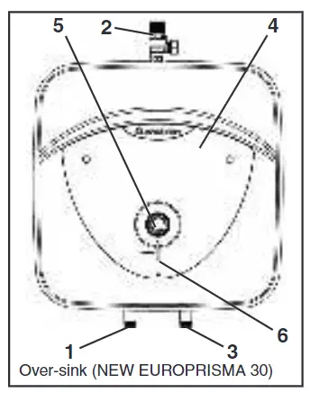
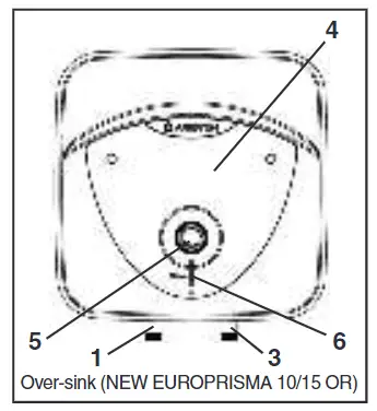
Description of water heater
 |
 |
 |
- Hot water outlet (1/2” male BSP)
- Temperature and pressure relief valve (30 liters only)
- Coldwater inlet (1/2” male BSP)
- Control cover
- Regulation knob
- Heating neon
TECHNICAL SPECIFICATIONS
|
Product information |
|||||
| Product range | 10 | 15 | 30 | ||
| Weight (kg) | 6,6 | 7,4 | 12,8 | ||
| Installation | Oversink | Undersink | Oversink | Undersink | Oversink |
| Model | Refer to the nameplate | ||||
| Qelec (kWh) | 2,442 | 3,080 | 2,525 | 3,026 | 2,775 |
| Load profile | XXS | S | |||
| Lwa | 15 dB | ||||
| nWH | 35,5% | 29,4% | 34,6% | 29,9% | 32,1% |
| Capacity (L) | 10 | 15 | 30 | ||
| Heat loss | – | – | – | – | 0.75 kWh/day |
| Heat up times (15–60°C) | – | – | – | – | 30 minutes |
| Weights when full (kg) | 17 | 17 | 23 | 23 | 43 |
| maximum inlet pressure | 3.5bar | 3.5bar | 3.5bar | 3.5bar | 3.5bar |
| maximum operating pressure | 6bar | 6bar | 6bar | 6bar | 6bar |
The power consumption data in the table and the other information given in the Product Data Sheet (Enclosure A to this manual) are defined in relation to EU Directives 812/2013 and 814/2013.Products equipped with regulator knobs have the thermostat positioned in the setting condition at its set <ready to use> position shown in the Data Sheet (Enclosure A), used by the manufacturer to declare the appliance’s energy class.This appliance is conforming with the international electrical safety standards IEC 60335-1 and IEC 60335-2-21.The CE marking of the appliances attests to its conformity to the following EC Directives, of which it satisfies the essential requisites:
- LVD Low Voltage Directive: EN 60335-1, EN 60335-2-21, EN 60529, EN 62233, EN 50106.
- EMC Electro-Magnetic Compatibility: EN 55014-1, EN 55014-2, EN 61000-3-2, EN61000-3-3.
- RoHS2 Risk of Hazardous Substances: EN 50581.
- ERP Energy-related Products: EN 50440.
- EN 12897:2006
User instructions
PLEASE KEEP THIS BOOKLET FOR FUTURE REFERENCEThe heater is insulated to a high standard therefore it may be left on all the time. The temperature of the water may be adjusted by turning the knob on the front of the heater, allow half an hour for the temperature to stabilize between settings. The maximum temperature is achieved with the knob turned fully clockwise. The <<E>> mark on the regulation knob indicates an <<economy>> setting and corresponds to a water temperature of 55 – 60°C. In hard water areas, we recommended a max. 60°C. The neon light shows when the heating element is working, under the control of the thermostat. If in doubt ring Ariston Thermo UK Ltd. Technical department 03332407777 Customer service department 03332408777.Note: The water heater does not have an “off” or “low” setting.Water Regulations and ByelawsThese regulations and bylaws ensure a good supply of wholesome water, and that only approved materials, pipes, and fittings are used to convey water.Building RegulationsThese are statutory documents and take priority over all other regulations and recommendations. The installation of an unvented hot water system of over 15 liters is classified as a “Controlled Service” and Regulation G3 applies. To meet the requirements of the regulation, installation of an unvented system should be undertaken by a “competent installer”. All installations of unvented hot water storage systems having a capacity of more than 15 liters should be notified to the relevant Local Authority by means of building notice or by the submission of full plans. It is important to note that it is a criminal offense to install an unvented hot water storage system over 15 liters without notifying the Local Authority.DeliveryThe EP models are supplied with the following:
| EP unvented water heater (with factory-fitted T&P model 30L) | x1 |
| Wall bracket | x1 |
| Pressure relief valve set at 6 bar | x1 |
| Dielectric junctions | x2 |
| Tundish (model 30L only) | x1 |
| Expansion Vessel (model 30L only) | x1 |
| Check Valve (model 30L only) | x1 |
| Pressure reducing valve (model 30L only) | x1 |
Important note: Dielectric junctions must be fitted to all models as they prevent an electrolytic reaction and safeguard against potential aggressive corrosion.
How the heater works
The heating element is controlled by a thermostat that senses the water temperature. The operating temperature can be adjusted by the regulation knob on the front of the heater.In addition to the thermostat, there is a thermal cut-out which is set to switch off the power to the element if the thermostat fails and the water temperature rises too high. Once the cut-out operates it can only be reset manually (this should be carried out by the installer – see maintenance).A magnesium anode is provided to prevent corrosion of the water container. The 30L model has a temperature and pressure relief valve on top of the heater which is a safety device to back up the thermostat and thermal cut-out. It works by sensing an excess water temperature or pressure and releasing the hot water to the discharge tundish and drain.The heater will only work in the vertical position as the element is shaped to heat the water at the bottom of the tank. The inlet pipe needs to deliver cold water to the bottom of the tank and the hot water outlet draws water from the top of the tank.When water is heated it expands, in a small unvented water heater of this type the expansion can normally be accommodated back into the cold water mains (not model 30L). Where this is not possible the installer will need to fit a set of cold water controls.Note: If a valve i.e. a nonreturn valve, water meter, pressure reducing valve, or any type of valve or fitting that acts as a non-return valve is installed on the cold water mains, this will prevent expansion. Therefore it will be necessary to install an expansion vessel (see pages 12&13 figs 2 & 3).Note: If in doubt always install a pressure reducing valve (limited to 3.5bar) and expansion vessel.
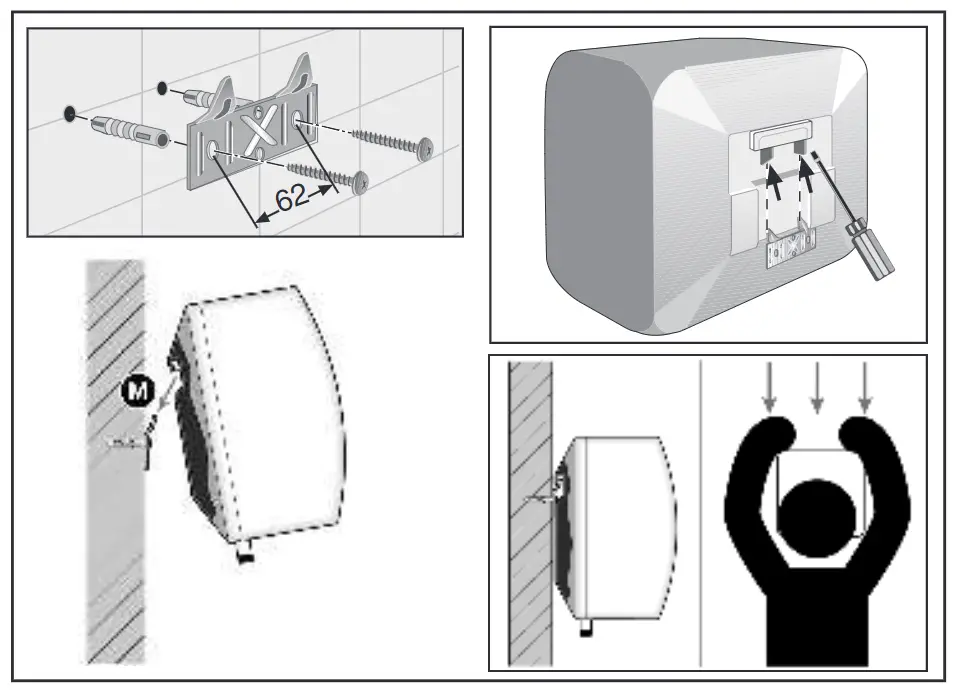
Installation instructions
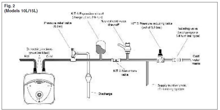
Before installing the heater read these instructions in full. If you are unsure please contact our technical service department (03332407777).Note: For further information please refer to the flow chart on page 19 which gives guidance on choosing controls.The installation must comply with all relevant Water Regulations/Byelaws and Building Regulations. The installer should check with the local water authority for confirmation of the maximum water supply pressure.a) SITING & FIXING WARNING:The appliance should be left packed until it is ready to be installed. When unpacking the 30 L model take care not to damage the temperature and pressure relief valve on the top of the heater. A drain has to be provided for any water discharged through the safety valves.Access to the heater is not normally needed on a day-to-day basis, but 300mm clearance to the front of the water heater should be kept for servicing and maintenance A cold water supply pressure between 1 and 3.5 bar is required (if the mains pressure is above 3.5 bar a pressure reducing valve must be installed).Please note that turning down the stop-cock will reduce flow not pressure.The outlet pressure from the reducing valve (if supplied) is 3.5 bar. A 240 VAC; 3 kW single-phase electrical supply is required. Position the heater against the wall and mark the position of the hooked wall bracket. Fasten the wall bracket to the wall using suitable screws and wall plugs (ensure that the wall is suitable to support the unit, allowing for the extra weight of water when it is full). Hang the heater on the bracket making sure that the heater is pulled well down onto the bracket, if necessary by forcing the hooks into the foam insulation. Ensure the unit is accessible and maintains sufficient clearances to allow for service and maintenance. Ensure the unit is installed in a place where freezing will not occur. Ensure a suitable low-level drain-off cock is installed on the hot and cold plumbing system.b) PLUMBING WARNING:The outlet from the temperature and pressure relief valve/pressure relief valve must not be for any other purpose. Take great care not to allow any swarf into the pipework or fittings, as this might impair the operation of the safety valve(s). The water connection may be carried out as per the following:1) Using the feed pipe to accommodate expansion (Schedule 2, Section 6: Paragraph 15 of the Water Supply (Water Fittings) Regulations 1999 and the Water Byelaws 2000, Scotland) (Fig. 1).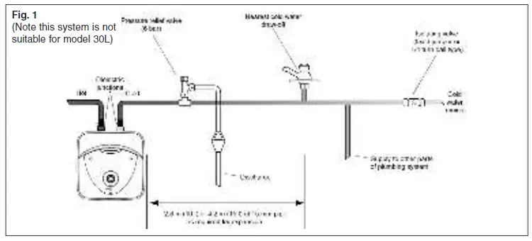 Do not fit any stop cocks or isolating valves within the distance required for expansion. If a pressure reducing valve is needed, due to a mains pressure of over 3.5 bar, an expansion control kit must be fitted regardless of expansion pipework installed. The expansion distances quoted are for 15mm pipes and can be approximately halved for 22mm pipes.2) Using a set of expansion controls (Fig. 2 & 3).
 |
 |
The model 30L is covered under the Building Regulations and therefore it is not possible to accommodate the expansion water within the system pipework and consequently, a set of expansion controls must be installed.Note: The discharge from relief valves must be made in a safe and conspicuous manner; therefore a tundish (Kit C) is available for 10 and 15-liter units if required.Please note that in all cases the dielectric junctions must be connected to the heater before any other connection is made (these prevent an electrolytic reaction).Only the use of copper pipe is recommended for connection to the heater.If any other material is used it must be able to withstand 90°C at 7 bar pressure for long periods.No valve must be fitted between the expansion/pressure relief valve and the water heater.All other required safety components to install the model 30L are supplied as a kit with the appliance: 15mm pressure reducing valve set at 3.5bar.The expansion vessel (charge pressure set at 3.5bar)”c) DISCHARGE PIPEWORK NOTE:The following guidelines refer to Building Regulation G3. It is good practice to follow these guidelines for all relief valve discharge pipework.
- The tundish must be vertical and fitted within 600 mm of the temperature & pressure relief valve and must be located with the cylinder. The tundish must also be in a position visible to the occupants and positioned away from any electrical devices. The discharge pipe from the tundish should terminate in a safe place where there is no risk to persons in the vicinity of the discharge and be of metal.
- Discharge pipes from the temperature & pressure relief and pressure relief valve may be joined together.
- The pipe diameter must be at least one pipe size larger than the nominal outlet size of the safety device unless its total equivalent hydraulic resistance exceeds that of a straight pipe 9 m long. i.e. Discharge pipes between 9 m and 18 m equivalent resistance length should be at least 2 sizes larger than the nominal outlet size of the safety device. Between 18 m and 27 m at least 3 times larger, and so on. Bends must be taken into account in calculating the flow resistance. See fig..5 and Table 2.
- The discharge pipe must have a vertical section of pipe at least 300 mm in length, below the tundish before any elbows or bends in the pipework.
- The discharge pipe must be installed with a continuous fall.
- The discharge must be visible at both the tundish and the final point of discharge, but where this is not possible or practically difficult; there should be clear visibility at one or other of these locations.Examples of acceptance are:i) Ideally below a fixed grating and above the water seal in a trapped gully.ii) Downward discharges at a low level; i.e. up to 100 mm above external surfaces such as car parks, hard standings, grassed areas, etc.These are acceptable providing that where children may play or otherwise come into contact with discharges, a wire cage or similar guard is positioned to prevent contact, whilst maintaining visibility.iii) Discharges at a high level; i.e. into a metal hopper and metal downpipe with the end of the discharge pipe clearly visible (tundish visible or not). Or onto a roof capableFig.. 4Suggest ways of terminating discharge pipes safely
 of withstanding high-temperature discharges of water 3 m from any plastic guttering systems that would collect such a discharge (tundish visible).iv) Where a single pipe serves a number of discharges, such as in blocks of flats, the number served should be limited to not more than 6 systems so that any installation can be traced reasonably easily.The single common discharge pipe should be at least one pipe size large than the largest individual discharge pipe to be connected. If unvented hot water storage systems are installed where discharges from safety devices may not be apparent i.e. in dwellings occupied by the blind, infirm or disabled people, consideration should be given to the installation of an electronically operated device to warn when discharge takes place. Note: The discharge will consist of scalding water and steam. Asphalt, roofing felt and non-metallic rainwater goods may be damaged by such discharges.
Table 2Sizing of the copper discharge pipe “D2” for common temperature valve outlets.
| Valve outlet size | Minimum size ofdischarge pipe D1* | Minimum size ofdischarge pipe D2*from tundish | Maximumresistance allowed,expressed as alength of pipe (i.e.no elbow or bends) | Resistance createdby each elbow orbend |
| G 1/2 | 15 mm | 22 mm | Up to 9 m | 0.8 m |
| 28 mm | Up to 18 m | 1.0 m | ||
| 35 mm | Up to 27 m | 1.4 m | ||
| G 3/4 | 22 mm | 28 mm | Up to 9 m | 1.0 m |
| 35 mm | Up to 18 m | 1.4 m | ||
| 42 mm | Up to 27 m | 1.7 m | ||
|
G 1 |
28 mm | 35 mm | Up to 9 m | 1.4 m |
| 42 mm | Up to 18 m | 1.7 m | ||
| 54 mm | Up to 27 m | 2.3 m |
Worked exampleThe example below is for a G 1/2″ temperature & pressure relief valve with a discharge pipe (D2) having 4 no. elbows and length of 7 m from the tundish to the point of discharge.From Table 2Maximum resistance allowed for a straight length of 22 mm copper discharge pipe (D2) from G 1/2″ T & P valve is 9 m. Subtract the resistance for 4 no. 22 mm elbows at 0.8 m each = 3.2 m.Therefore the maximum permitted length equates to: 5.8 m.As 5.8 m is less than the actual length of 7 m, therefore, calculate the next largest size.Maximum resistance allowed for a straight length of 28 mm pipe (D2) from G 1/2″ T & P valve equates to 18 m.Subtract the resistance for 4 no. 28 mm elbow at 1.0 m each = 4 m.Therefore the maximum permitted length equates to 14 m As the actual length is 7 m, a 28 mm (D2) copper pipe will be satisfactory.d) ELECTRICAL WARNING:The appliance must be earthed The electrical installation must be in line with the current I.E.E. wiring regulations.A mains supply of 240 VAC 3 kW (13 amps) is required (Fig. 5)Heat-resisting cable, round 3 core 1.5 mm (to BS 6141 table 8) should be used to connect to the electrical supply through either:– a 13 amp socket to BS 1363; or– a double pole fused isolating switch with a contact separation of 3 mm minimum on each pole.The cable enters the terminal compartment through a tube embedded in the foaminsulation, the entrance to this tube is on the rear right-hand side at the bottom.Flexible cables are color-coded as follows:Brown-live BlueBlue – neutralGreen and yellow-earth

Fig..5 EP 10/15 and EP 30 R 3KW wiring diagram
To enter into the terminal compartment unscrew the 2 screws on the cover. (To access the screws, remove the decorative caps on the front control access panel).e) COMMISSIONING
- Check that all the necessary components are supplied and for those not factory fitted, that they are the type recommended by the manufacturer for the particular water heater.
- Check that the water heater/components are undamaged.
- Check that the discharge pipe is plumbed so that it falls continuously and that no taps, valves, or other shut-off devices are installed in the pipe.
- Check that the discharge pipe drains safely to waste and is readily visible.
- Check, in the case where some components are not factory fitted, that they are marked so as to refer to the warning label on the water heater.
- Open all outlet taps.
- Turn on the mains water supply.
- Close taps in turn as water flow stabilize with no air bubbles.
- Check for leaks. – Check that no water is passing through the safety valve(s).
- Test the operation of the safety valve(s) by lifting/turning the lever/knob, and observing that water flows through and safely to waste.
- Switch on electricity and set the thermostat to 60°C to reduce the build-up of scale in hard water areas.
- Check the water heats up. – Check that <<warning to user label>> is secure and visible on the heater and related warning labels are fitted to the controls.
- Demonstrate operation to the user, including operation of safety valve(s) and what to do if it/they operate(s).
- Give this handbook to the user and discuss future maintenance.
- Drain and refill the entire system ensuring it is flushed in accordance with BS6700.
Maintenance
a) For the user In order to obtain the best performance from the heater, the sacrificial anode must be checked every year and replaced as necessary.If the heating element is heavily coated with the scale we recommend descaling and removing any lime deposit from the heater at the time of this inspection. Where the additional cold water controls are fitted, the expansion vessel will need to be recharged by the installer.Important note: The heater must be serviced annually. Failure to service which includes inspection and replacement of the sacrificial anode will invalidate the warranty.b) For the installerWARNING: Switch off the power firstAccess to the electrical components, the magnesium anode, and water container is gained by unscrewing the 2 screws on the front cover.If the thermal cut-out has operated the cause must be found before resetting.To drain the heater close the service valve and:i) for under-sink models disconnect pipes and removed the heater from the wall.ii) for over-sink models undo the cold water supply pipe and open a hot water tap. The heating element may be removed (after taking out the thermostat vials on model 30 L) by undoing the M6 nut. The assembly should then be turned through 90° anti-clockwise to ease removal from the water container. Once the element is free from the water container the anode may then be inspected and removed if necessary.When reassembling the cover make sure that the regulation knob is coupled with the thermostat.Check controls (where fitted) as per the following:
- Line strainer – with the water supply turned off remove the screen from the strainer and clean of any detritus;
- Expansion vessel – with the water supply turned off and taps open, check the expansion vessel pressure and top up as necessary;
- Temperature & pressure relief valve – with the water supply turned on, check manually by lifting the test lever/turning the test knob (ensure valve closes after testing);
- Expansion relief valve check manually by turning the test knob (ensure valve closes after testing);
- Discharge pipes (D1) – from both temperature & pressure relief and expansion relief valve for obstructions;
- Tundish & discharge pipe (D2)- open either valve gradually to produce a full bore discharge into tundish and D2 without any back pressure;
- Pressure reducing valve – check that the correct outlet pressure is being maintained by recording the pressure at an in-line terminal fitting i.e. tap.
Fault finding
- Pressure and temperature valve dripping/running all the time.Cause: Thermal cut-out and thermostat have failed (this is only the case if the water being discharged is near to boiling).Mains pressure is too high. A pressure-reducing valve must be fitted (see fig. 3).
- Pressure relief valve dripping/running all the time.Cause: Mains pressure is above 3.5 bar. A pressure-reducing valve must be fitted (see fig. 2).
- Dripping while unit heating.Cause: Not enough pipework for expansion; or stop-cock, non-return valve, or pressure reducing valve has been fitted on the cold mains supply (see fig. 2). If an expansion vessel has been fitted, the charge may have failed.
- No hot water.Cause: Thermal cut-out has operated. The heating element has burnt out. The thermostat is faulty.
- Milky water.Cause: This is a result of heavily limed and oxygenated water being heated. This is harmless and the cause is the water or a loose jumper washer in the outlet tap and not the heater itself.
- No water at all.Cause: Valve incorrectly fitted. Debris in the mains.The mains water supply turned off.
- Grey metallic deposit in the waterCause: Corrosion of the sacrificial anode.(Note: Corrosion of the sacrificial anode is normal operation of the unit)
- Rapid depletion of the sacrificial anode (see 7)Cause: Di-electric junctions not fitted Water softener fitted on the incoming supply to the water heater (Softened will cause the anode to deplete more rapidly than hard water)
Note Whilst Ariston does not advise against the use of water softener devices, the end-user must be advised that rapid depletion of the sacrificial anode may occur as a result of the softened water which can result in metallic grey deposit in the water.
 WE MAKE USE OF RECYCLED PAPER
Manufactured by:Ariston Thermo S.p.A.Viale Aristide Merloni, 45 60044 Fabriano (AN) Tel. (+ 39) 0732 .6011 ariston.comCommercial subsidiary:Ariston Thermo UK Ltd Artisan Building Hillbottom Road High Wycombe HP12 4HJwww.ariston.co.uke-mail: inf[email protected]Customer Service: 0333 240 8777Technical Advice: 0333 240 7777
 420010616600 0415
References
[xyz-ips snippet=”download-snippet”]