
Armacost RibbonFlex Home Smart/Wi-Fi LED Tape Light Kit
SAFETY INFORMATION
- DANGER: Risk of eye damage. Do not stare directly at the LED chips of this LED strip.
- CAUTION: Do not power LED tape while coiled on reel.
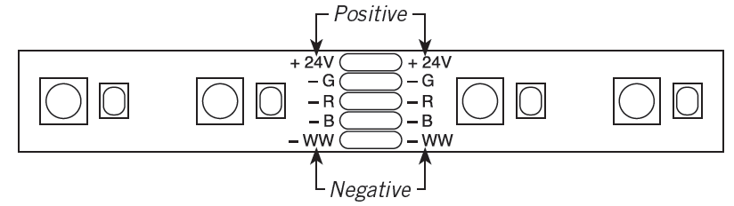
- IMPORTANT: Always observe polarity for 24-volt connections, positive (+) to positive and negative (–) to negative.
- IMPORTANT: Do not install Class 2 low voltage wiring in the same runs as AC main power. If AC and low voltage wires cross, keep them at 90- degree angles. Use only insulated staples, plastic ties, or wire support clips to secure cords and wires.
- NOTICE: LED flexible tape lighting rating: 24VDC 1A.
- Only use the 24-volt LED lighting power supply which has been provided with this kit.
- Do not bend, crush or pull the cable. Protect from sharp edges, oil and heat.
- For indoor/dry location use only.
- Ensure the connectors are securely fastened before operating the tape.
- Electrical waste should not be disposed of with household waste. Please recycle where facilities exist.
Two-year limited warranty
WHAT IS COVEREDThe manufacturer warrants this fixture to be free from defects in materials and workmanship for a period of two (2) years from date of purchase.This warranty applies only to the original consumer purchaser and onlyto products used in normal use and service. If this product is found to be defective, the manufacturer’s only obligation, and your exclusive remedy, is the repair or replacement of the product at the manufacturer’s discretion, provided that the product has not been damaged through misuse, abuse, accident, modifications, alteration, neglect, or mishandling. This warranty shall not apply to any product that is found to have been improperly installed, set-up, or used in any way not in accordance with the instructions supplied with the product. This warranty shall not apply to a failure of the product as a result of an accident, misuse, abuse, negligence, alteration, faulty installation, or any other failure not relating to faulty material or workmanship. This warranty shall not apply to the finish on any portion of the product, such as surface and/or weathering, as this is considered normal wear and tear.WHAT IS NOT COVEREDThe manufacturer does not warrant and specifically disclaims any warranty, whether expressed or implied, of fitness for a particular purpose, other than the warranty contained herein. The manufacturer specifically disclaims any liability and shall not be liable for any consequential or incidental loss or damage, including but not limited to any labor/ expense costs involved in the replacement or repair of said product.Contact customer support at 410-354-6000, [email protected], or visit armacostlighting.com/support.
Installation considerations
- Where will you locate your power supply?
- How will you run and conceal the wires to your LED tape lighting?
- What is the best mounting position for the LED tape light to achieve your desired effect?
- See the section titled “Mounting options” for cabinet lighting placement tips.
PACKAGE CONTENTS

INSTALLATION
Cutting the tape light (optional)
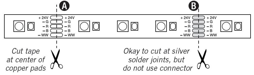
- To use the included connectors, cut the LED tape with scissors in the center of a copper pad (position A) as shown, or attach the connector to the copper pad found at the end of the tape.
- The tape can also be cut at silver solder joints (position B), but this cut point should be used for soldered connections only.

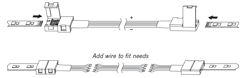
- Use a wire lead connector to make turns and go around corners. They can also be spliced and extended for gaps of any size. 18-20 AWG wire is recommended for custom lengths (not included).
- IMPORTANT: Make sure to observe polarity when making connections, positive to positive and negative to negative. Check to see that the wire colors and the polarity markings printed on the tape line up.
NOTE: Be sure all 24-volt connections are secure and protected from electrical shorting. Options include electrical tape, small wire nuts, crimp connectors, etc.
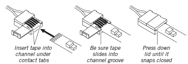
How to use included connectors
- The wire lead connectors are used to join two sections of LED tape.
- Open the lid of the connector opposite the wire.
- Peel about 1/4 inch of the paper from the LED strip adhesive backing at the connection point.
- Use a gentle side-to-side motion to slide the strip into the connector, making sure the tape slides under the internal connector contact points.
- Perform a power test to be sure the connection is secure. If the LEDs flicker or do not light, repeat the steps in this guide.
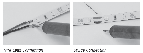
Soldering the LED tape (optional)
- Soldering is another method for joining wires to the tape light and joining sections of tape light directly together.
Preparing the assembly location
Power the LED tape lighting and temporarily hold or tape into position with painter’s tape or masking tape – do not remove the adhesive paper backing.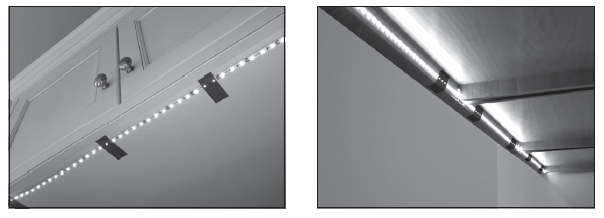
- Adjust the lighting to various angles and positions to get the desired level of illumination and lighting appearance. If the LEDs create undesirable light spots on walls, or reflections, reposition the tape light strip farther away from surfaces or try a different mounting angle.
- Once you have determined your final mounting position, remove any dirt and dust present where the tape will be applied. Mounting surfaces should be clean, completely dry, and as dust-free as possible. For best results, install when temperatures are above 60ºF (15ºC). When installing on painted surfaces, paint should be fully cured based on manufacturer’s cure time.
Installing the LED strip
- Working from one end to the other, remove the paper backing protecting the adhesive and fi rmly press the LED tape down with your fi ngers or a clean cloth, taking care not to press on the individual LEDs.
- Support and secure the power cables leading to the tape light with the included wire support clips.
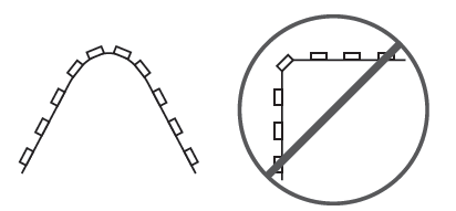
- NOTE: Although the LED tape can be installed in curved and irregular spaces, avoid sharp bends or bending on the solder joints as you could damage the LED tape light. If an LED is inadvertently damaged and fails to light, the remaining LEDs will continue to operate.
Installing the power supply
- IMPORTANT: Do not power the LED tape while on the reel, as the LEDs will overheat.
- Connect the AC power cord to a live outlet.
- If connected to a switched outlet, be sure the power is switched ON for proper remote operation.
MOUNTING OPTIONS
- To surface mount the LED tape light under a set of cabinets in one continuous run, you may need to drill a 1/2 in. hole through any cabinet side lip that may be present. Install LED tape light through the hole and surface mount as a continuous run.
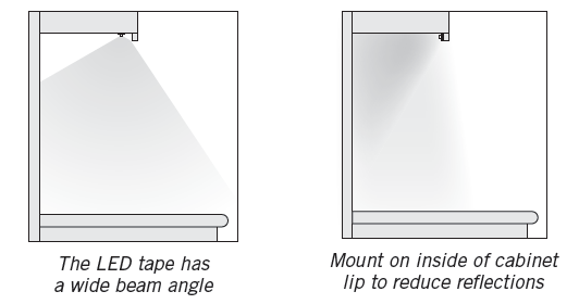
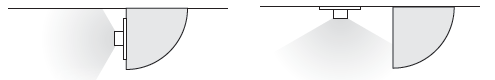
- For maximum light output and to focus light on the work surface, mount the tape light 1-2 inches behind the front cabinet lip. This mounting position works best with dull or matte finished countertops.
- To eliminate bright spots from highly reflective countertops, mount the tape light on the inside back of the cabinet lip frame facing towards your backsplash. Because of the wide beam angle of the tape light, this mounting position will still provide ample lighting.
- When mounting under a cabinet or a shelf with no lip to hide the LED tape light strip, create a visual barrier using a piece of quarter round molding or any angle trim to hide the LEDs.
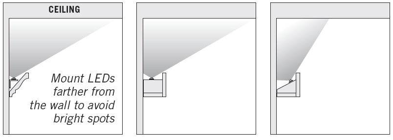
Creating above cabinet uplighting
- Most cabinet tops have uneven surfaces. To create indirect uplighting over cabinets, simply mount the LED tape on any rigid strip (e.g., thin lattice or corner guard molding) and place on top of cabinets. Angle the strip position to achieve the desired illumination.
- For a seamless glow and to avoid bright light spots, move the LED tape light strip further from adjacent walls.

OPERATION
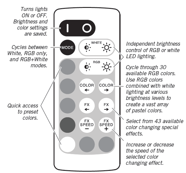
Functions of the remote
- Pull out the plastic battery barrier sheet from the battery compartment located on the bottom of the remote.
- The remote does not require line-of-sight to operate the lights. Range will vary depending on your building structure and where the receiver on the tape light is mounted.
- The remote can operate up to 50 feet in optimal conditions, but each installation has unique variables that may affect range.
Pairing multiple kits
The remote in each kit comes paired with the tape light. For larger installations, multiple kits can be paired together for control by a single remote.PAIRING
- Unplug the power supply for the kit that is to be paired. Wait 5 seconds.
- Plug in the power supply, then within 10 seconds press and hold the red color preset and the RGB brightness up buttons on the remote at the same time.
- The lights will flash to indicate a successful pairing This operate with the remote used in this procedure. Repeat with other kits and remotes.
- NOTE: Dynamic effects will not stay synchronized between multiple receivers.

TO RETURN TO SINGLE-REMOTE OPERATION
For each kit, perform the following steps using a unique remote:
- Unplug the power supply for the kit that is to be returned to single-remote operation.
- Plug in the power supply, then within 10 seconds press and hold the red color preset and the RGB brightness up buttons at the same time.
- (The lights will flash to indicate the signal has been received)
- Perform the two steps above a second time to complete the process
TO RESET TO FACTORY DEFAULTTo reset the Wi-Fi setting and remote control pairing:
- Unplug the receiver. Plug in after five seconds.
- Press the purple color preset and the FX SPEED+ keys simultaneously for about three seconds, within ten seconds of the receiver being powered on.
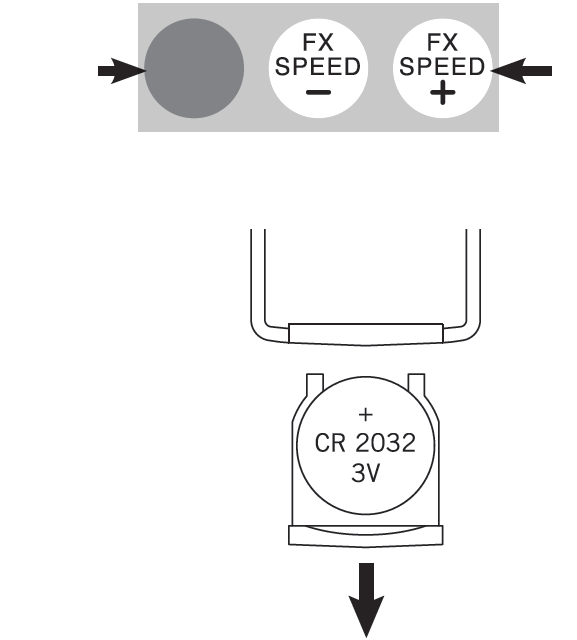
Changing the battery
- To replace the battery, push in the tab on the side of the battery tray, and pull the tray out of the remote. Refer to the instructions on the back of the remote.
- Always purchase the correct size and grade of battery that is most suitable for the intended use.
- Ensure the battery is installed correctly with regard to polarity (+ and –).
- Remove battery from the equipment when it is not being used for an extended period of time.
- Remove used batteries promptly.
- WARNING: The remote contains a CR2032 DC 3V button battery. If swallowed, it could cause severe injury or death within 2 hours. Seek medical attention immediately.
Setting up a Wi-Fi connection
Install the Tuya app (available at the iOS and Google Play stores) to set up a Wi-Fi connection. Before setup, make sure the controller is in factory default mode and not connected to other wireless routers.
CARE AND CLEANING
- To clean the light, use a clean dry or slightly damp cloth.
- Do not use cleaners with chemicals, solvents or harsh abrasives as damage to the light strip may occur.
TROUBLESHOOTING
The LED strip will not light.
- The power supply does not have power. Make sure the plug is fully inserted into a live 120-volt outlet. Check connections and circuit breaker if direct wiring.
- Batteries in the remote are dead, improperly installed, or the battery protector has not been removed. Make sure the battery protective strip is removed. Check that the orientation and type of battery are correct and that the battery is not depleted.
- The remote is too far from the receiver. The remote can operate up to 50 feet in optimal conditions, but each installation has unique variables that may affect range.
Only part of the LED strip lights.
- A connection point is faulty. Check for secure connections at the point that is not lit. Confirm that polarity is the same between the lit and unlit segments.
The fuse blows or a circuit breaker trips when the light is turned on.
- A wire is exposed. Discontinue use of the lamp. Unplug the unit from the wall. Contact a qualified electrician.
FCC STATEMENT
This device complies with part 15 of the FCC Rules. Operation is subject to the following two conditions:
- This device may not cause harmful interference, and
- this device must accept any interference received, including interference that may cause undesired operation.
CAUTION: Any changes or modifications not expressly approved by the party responsible for compliance could void the user’s authority to operate the equipment.NOTE: This equipment has been tested and found to comply with the limits for a Class B digital device, pursuant to part 15 of the FCC Rules. These limits are designed to provide reasonable protection against harmful interference in a residential installation. This equipment generates, uses and can radiate radio frequency energy and, if not installed and used in accordance with the instructions, may cause harmful interference to radio communications. However, there is no guarantee that interference will not occur in a particular installation. If this equipment does cause harmful interference to radio or television reception, which can be determined by turning the equipment off and on, the user is encouraged to try to correct the interference by one or more of the following measures:
- Reorient or relocate the receiving antenna.
- Increase the separation between the equipment and receiver.
- Connect the equipment into an outlet on a circuit different from that to which the receiver is connected.
- Consult the dealer or an experienced radio/TV technician for help.
CUSTOMER SUPPORT
Email: [email protected] | Phone: 410-354-6000 Monday–Friday, 9 a.m.–5 p.m., EST
![]()
Baltimore, Marylandarmacostlighting.com© 2020 Armacost Lighting. All rights reserved.
References
[xyz-ips snippet=”download-snippet”]