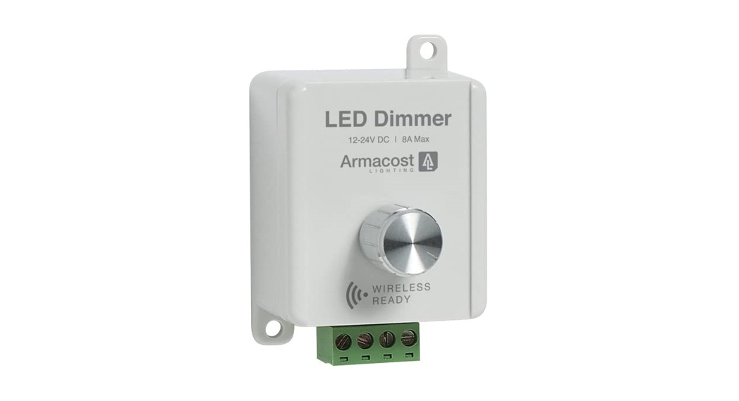
Remote Touch LED DimmerModel TDAL14, Item # 511121

- Provides full range brightness control of low-voltage, white LED lighting with a touch of the finger
- Stainless steel sensor disk provides discreet switching and dimming for many applications
- Works with both 12-volt DC and 24-volt DC LED lighting
- Dimming will save energy and extend LED life
Important
This dimmer works on body capacitance, the naturally occurring electrical energy stored within the human body. The dimmer sensor detects minute changes in electromagnetism to turn on/off and dim your lighting. Where you mount the touch sensor and sensor dimmer module can influence the sensitivity and functionality of this device.
- For best results, the Remote Touch LED Dimmer should be electrically isolated from other devices. Keep your power supply a few feet away from the sensor and dimmer module.
- Radio devices, AC motors, transformers, power supplies, and electrical appliances can generate interference, which may cause inconsistent sensitivity to the touch operation. Keep sensor and wire lead away from these devices if possible.
- Although the sensor is designed to mount to non-conductive surfaces, such as wood and plastics, it may also work on some metal surfaces.
- Always test the device in your desired location to make sure it functions properly.
- If the touch sensor operates intermittently or has reduced sensitivity, completely remove power to the unit for 5 seconds, then reset and try again. If the issue persists, try moving the dimmer module and sensor wire to a new location.
- The lead wire to the sensor should be kept as short as possible. Note: If you touch the wire, it can also turn on/off your lighting; this is normal.
Warning
- For use only with 12-volt DC or 24-volt DC low-voltage, single color LED lighting. Do not connect this device to a 120-volt AC current.
- Use only with 12-volt or 24-volt DC constant voltage electronic power supplies. Not compatible with magnetic power supplies or low-voltage power supplies with AC output.
- Do not exceed 96 watts of lighting when used with 12-volt LEDs or 192 watts when used with 24-volt LEDs.
- Use only insulated staples or plastic ties to secure cords and wires. Route and secure wires so they will not be pinched or damaged.
- For dry location use; keep away from water.
SPECIFICATIONS
Input Voltage …………………………………………………………….12- or 24-volt DCOutput Current ……………………………………………………………………………. 8AMax Load with 12-volt DC Lighting …………………………………………… 96 wattsMax Load with 24-volt DC Lighting …………………………………………. 192 wattsDimming Technology ………………………………… Pulse Width Modulation (PWM)Switch Type …………………………………………………………… Touch CapacitanceCountry of Origin ………………………………………………………………………China
Limited one-year warranty. Improper installation, improper powering, abuse, or failure to use this device for its intended purpose will void warranty. Proof of purchase is required for all returns. Questions? Email [email protected].
![]()

INSTALLATION GUIDELINES
After selecting the location for the remote touch sensor disk, begin by routing the bare touch sensor wire through any walls or cabinetry necessary to reach your point of control. Cut the sensor wire to the length needed for your application – do not coil extra wire. A cut sensor wire can be spliced back together to restore full lead length. The 48 in. wire lead maximum should be observed to ensure consistent operation. Lengths beyond this point may reduce the sensitivity of the dimmer operation.
Installing the touch sensor disk
- The sensor disk is designed to be surface or counter-sunk/flush-mounted.
- The sensor wire can run along the mounting surface or through a small hole to the back of the disk. For a professional flush-mount installation, use a standard 1 in.Forstner drill bit to create a recess in which to insert the touch sensor disk. Your mounting surface should be drilled out to a depth of approximately 1/16 in.
Connecting the sensor wire to the sensor disk
Peel one side of the adhesive disk, strip the end of the sensor wire, then attach the stripped end of the wire to the sticky side of the adhesive disk. Fan out the individual strands of the wire to maximize contact area on the sensor disk. Stick the wires on the dull side of the stainless steel disk. When properly mounted, the bare sensor wire strands should be sandwiched between the touch sensor disk and the adhesive disk. For wire run through your mounting surface, run the wire through the center hole of the adhesive disk from the opposite side before adhering it to the metal sensor disk.
Painting the sensor disk
The sensor disk is made of high-quality stainless steel to provide a professional finish that will not rust or tarnish. However, in some applications, you may want to paint the disk to match the finish of your cabinetry. Armacost Lighting recommends using spray paint specifically made for metal. Use a light coat of paint. Do not paint the backside of the disk to which the sensor wire will be attached.
Not using the sensor disk
The sensor wire can be attached to many metals, such as a cabinet pull, for discreet control of your LED lighting. Compatible hardware includes copper, brass, and most ferrous metals. Aluminum and aluminum alloys will not work.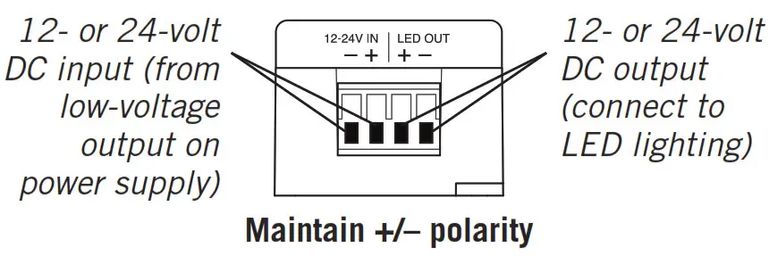
report this ad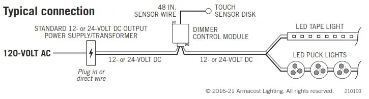
[xyz-ips snippet=”download-snippet”]