aruba 503H Hospitality Access Points Installation Guide
The Aruba AP-503H Access Points are high-performance, multi-radio wireless devices that can be deployed in either controller-based (AOS) or controller-less (Instant) modes in hospitality and branch or teleworker deployments. The Aruba AP-503H Hospitality Access Points support the full 802.11ax (Wi-Fi 6) feature set with dual 2×2 MIMO radios, deliver locationing functions, and can serve as a flexible IOT gateway, delivered through the built-in BLE and 802.15.4 radio.
A variety of mounting scenarios are supported by a range of mount kits (sold separately). Make sure to purchase the correct mount kit for the intended deployment of the AP.
Hardware Overview
The following sections outline the hardware components of the Aruba AP-503H Access Points.
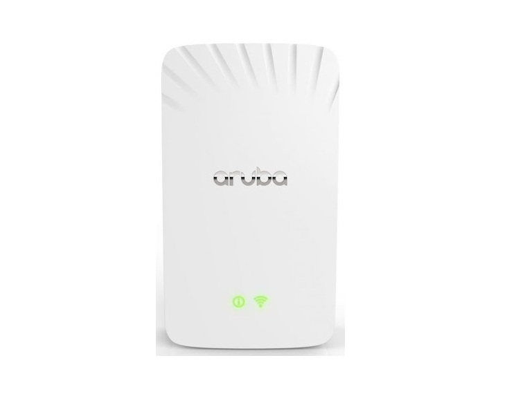
Figure 1 AP-503H (front view)
Figure 2 AP-503H (side and rear view)
Figure 3 AP-503H (bottom view)
LEDs
The hidden LED displays located on the front panel of the access point indicate the following functions:
System Status
The System Status LED indicates the operating condition of the access point, See Table 1.
Table 1 System Status LEDs
| Color/State | Meaning |
| Off | Device powered off |
| Green- blinking 1 | Device booting, not ready |
| Green- solid | Device ready, fully functional, no network restrictions |
| Green- flashing pattern 12 | Device ready, fully functional, uplink negotiated in sub-optimal speed (<1Gbps) |
| Green- flashing pattern 23 | Deep sleep mode |
| Red | System error condition – Immediate attention required |
- Blinking: one second on/one second off, 2 second cycle.
- Flashing Pattern 1: mostly on, briefly off, 2 second cycle.
- Flashing Pattern 2: mostly off, briefly on, 2 second cycle.
Radio Status
The Radio Status LED indicates the operating mode of the access point’s radios. See Table 2.
Table 2 Radio Status LEDs
| Color/State | Meaning |
| Off | AP powered off, or both radios disabled |
| Green- solid | Both radios enabled in access mode |
| Green- blinking | One radio enabled in access mode, other disabled |
| Amber- solid | Both radios enabled in monitor mode |
| Amber- blinking | One radio enabled in monitor mode, other disabled |
| Green/Amber- alternating1 | Green: one radio in access mode Amber: one radio in monitor mode |
Alternating: one second each color, 2 second cycle.
LED Display Settings
The LEDs have three operating modes that can be selected in the system management software:
- Default mode: Refer to Table 1 and Table 2
- Off mode: LEDs are off
- Blink mode: LEDs blink green
Force the LEDs into off mode and back to software defined mode by pressing the reset button for a short duration. Warning: pressing the reset button for longer than 10 seconds may cause the AP to reset and return to factory default state.
Console Port
The 5-pin Micro-B connector is located on the back of this device. Use the proprietary AP-CBL-SERU cable for direct management of this device when connected to a laptop or serial console (a standard USB cable cannot be used for this interface). For pin-out details, refer to Figure 4.
Figure 4 Micro-B Port Pin-out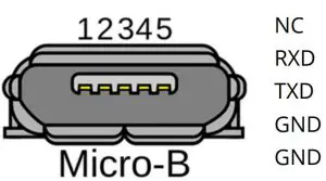
Ethernet Ports
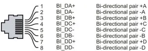
The Aruba AP-503H access points are equipped with one active uplink Ethernet port E0, shown in Figure 2. The port is 10/100/1000 Base-T, auto-sensing MDI/MDX, which supports uplink connectivity when linked by an Ethernet cable. Refer to Figure 5 for a detailed port pin-out. The Aruba AP-503H access points support downlink network connectivity through E1-E2 Ethernet ports. The ports are 10/100/1000Base-T auto-sensing MDI/MDX.
Figure 5 AP-503H (Ethernet Port)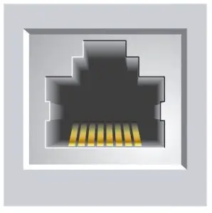
Physical Security Options
- A Kensington Lock Slot is available with the desktop mount accessory
- A security screw hole can be used with the mounting bracket
Reset Button
The reset button located on the side of the device (showed in Figure 2) can be used to reset the access point to factory default settings or turn off/on the LED display.
- Use one of the following methods to reset the access point to factory default settings:
- To reset during normal operation:
- Hold the reset button for more than 10 seconds while the access point is running.
- Release the reset button.
- To reset during power up, hold the reset button while the access point is powering up. The system status LED will flash again within 15 seconds indicating that the reset is completed. The access point will now continue to boot with the factory default settings.
- To toggle the LED display between Off and Normal:During the normal operation of the access point, shortly press and release the reset button using a small, narrow object, such as a paperclip.
Bluetooth Low Energy / Zigbee Radio
Aruba AP-503H Access Points are equipped with an integrated BLE and Zigbee radio that provides the following capabilities:
- location and asset-tracking applications
- wireless console access
- IoT gateway applications
Power
Ethernet port E0 supports PoE-in (AP is a class 3 802.3af PoE-PD device), allowing the device to draw power from compliant PoE power sources. If PoE is not available, the access point has a 12V DC power input to support an AC-to-DC power adapter (sold separately). When both PoE and DC power sources are available, the DC power source takes priority.
Before You Begin
Refer to the sections below before beginning the installation process.
FCC Statement: Improper termination of access points installed in the United States configured to non-US model controllers will be in violation of the FCC grant of equipment authorization. Any such wilful or intentional violation may result in a requirement by the FCC for immediate termination of operation and may be subject to forfeiture (47 CFR 1.80).
Pre-Installation Checklist
Before installing your Aruba AP-503H Access Points, be sure that you have the following (not included with the AP):
- A mount kit compatible with the AP and mount surface
- A Cat5E or better UTP cable with network accessOptional items:
- A compatible power adapter with cord
- A compatible PoE midspan injector with power cord
- An AP-CBL-SERU console cableAlso, make sure at least one of the following network services is supported:
- Aruba AP-503H access points Discovery Protocol (ADP)
- DNS server with an “A” record
- DHCP Server with vendor-specific options
Note: Aruba Networks, in compliance with governmental requirements, has designed the Aruba AP-503H Access Points so that only authorized network administrators can change the settings. For more information about access point configuration, refer to the Access Point Software Quick Start Guide.
Identifying Specific Installation Locations
Use the access point placement map generated by Aruba AP-503H access points RF Plan software application to determine the proper installation location(s). Each location should be as close as possible to the center of the intended coverage area and should be free from obstructions or obvious sources of interference. These RF absorbers/reflectors/interference sources will impact RF propagation and should be accounted for during the planning phase and adjusted for in RF plan.
Identifying Known RF Absorbers/Reflectors/Interference Sources
Identifying known RF absorbers, reflectors, and interference sources while in the field during the installation phase is critical. Make sure that these sources are taken into consideration when you attach an access point to its fixed location. RF absorbers include:
- Cement/concrete—Old concrete has high levels of water dissipation, which dries out the concrete, allowing for potential RF propagation. New concrete has high levels of water concentration in the concrete, blocking RF signals.
- Natural Items—Fish tanks, water fountains, ponds, and trees
- BrickRF reflectors include:
- Metal Objects—Metal pans between floors, rebar, fire doors, air conditioning/heating ducts, mesh windows, blinds, chain link fences (depending on aperture size), refrigerators, racks, shelves, and filing cabinets.
- Do not place an access point between two air conditioning/heating ducts. Make sure that access points are placed below ducts to avoid RF disturbances.RF interference sources include:
- Microwave ovens and other 2.4 or 5 GHz objects (such as cordless phones)
- Cordless headset such as those used in call centers or lunch rooms.
![]() RF Radiation Exposure Statement: This equipment complies with RF radiation exposure limits. This equipment should be installed and operated with a minimum distance of 7.87 inches (20cm) between the radiator and your body for 2.4 GHz and 5 GHz operations. This transmitter must not be co-located or operating in conjunction with any other antenna or transmitter.
RF Radiation Exposure Statement: This equipment complies with RF radiation exposure limits. This equipment should be installed and operated with a minimum distance of 7.87 inches (20cm) between the radiator and your body for 2.4 GHz and 5 GHz operations. This transmitter must not be co-located or operating in conjunction with any other antenna or transmitter.
![]() Portable RF communications equipment should be used no closer than 30 cm (12 inches) to any part of the access point. Otherwise, degradation of the performance of this equipment could result.
Portable RF communications equipment should be used no closer than 30 cm (12 inches) to any part of the access point. Otherwise, degradation of the performance of this equipment could result.
Access Point Installation
![]() All Aruba access points should be professionally installed by an Aruba-Certified Mobility Professional (ACMP). The installer is responsible for ensuring that grounding is available and meets applicable national and electrical codes. Failure to properly install this product may result in physical injury and/or damage to property.
All Aruba access points should be professionally installed by an Aruba-Certified Mobility Professional (ACMP). The installer is responsible for ensuring that grounding is available and meets applicable national and electrical codes. Failure to properly install this product may result in physical injury and/or damage to property.
![]() For indoor use only. The access point, AC adapter, and all connected cables are not to be installed outdoors. This stationary device is intended for stationary use in partly temperature controlled weather-protected environments (class 3.2 per ETSI 300 019).
For indoor use only. The access point, AC adapter, and all connected cables are not to be installed outdoors. This stationary device is intended for stationary use in partly temperature controlled weather-protected environments (class 3.2 per ETSI 300 019).
Software
Aruba AP-503H access points require ArubaOS or ArubaInstant 8.7.1.0 or later. For instructions on choosing operating modes and initial software configuration, refer to the Access Point Software Quick Start Guide.
![]() Aruba access points are classified as radio transmission devices, and are subject to government regulations of the host country. The network administrator(s) is/are responsible for ensuring that configuration and operation of this equipment is in compliance with their country’s regulations. For a complete list of approved channels in your country, refer to the Aruba Downloadable Regulatory Table at www.arubanetworks.com/techdocs/DRT/ Default.htm.
Aruba access points are classified as radio transmission devices, and are subject to government regulations of the host country. The network administrator(s) is/are responsible for ensuring that configuration and operation of this equipment is in compliance with their country’s regulations. For a complete list of approved channels in your country, refer to the Aruba Downloadable Regulatory Table at www.arubanetworks.com/techdocs/DRT/ Default.htm.
Verifying Post-Installation Connectivity
The integrated LED on the access point can be used to verify that the access point is receiving power and initializing successfully (see Table 1 and Table 2). Refer to the Access Point Software Quick Start Guide for further details on verifying post-installation network connectivity.
Electrical and Environmental Specifications
For additional specifications on this product, please refer to the product data sheet at www.arubanetworks.com/ products/networking/access-points/.
Electrical
- Ethernet:
- E0: 10/100/1000 Base-T auto-sensing MDI/MDX
- IEEE 802.3i (10 Base-T) IEEE 802.3u (100 Base-T). IEEE 802.3ab (1000 Base-T)
- Power:
- Power over Ethernet IEEE 802.3af
- 12V DC power interface, support powering through AC-to-DC power adapter
- Maximum power consumption: Refer to datasheet
Note: If a power adapter other than the Aruba-approved adapter is used in the US or Canada, it should be NRTL listed, with an output rated 12V DC, minimum 1.045A, marked “LPS” and “Class 2,” and suitable for plugging into a standard power receptacle in the US and Canada.
Environmental
- Operating:
- Temperature: 0°C to +40°C (+32°F to +122°F)
- Humidity: 5% to 93% non-condensing
- Storage and transport:
- Temperature: -40°C to +70°C (-40°F to +158°F)
- Humidity: 5% to 93% non-condensing
![]() Caution: For indoor use only. The access point, AC adapter, and all connected cables are not to be installed outdoors. This stationary device is intended for stationary use in indoor temperature controlled and weather-protected environments (ETSI Class 3.1per ETSI 300 019).
Caution: For indoor use only. The access point, AC adapter, and all connected cables are not to be installed outdoors. This stationary device is intended for stationary use in indoor temperature controlled and weather-protected environments (ETSI Class 3.1per ETSI 300 019).
Regulatory Information
For the purpose of identification needed for regulatory compliance certifications, this product has been assigned a unique regulatory model number (RMN). The regulatory model number can be found on the product nameplate label, along with all required approval markings and information. When requesting compliance information for this product, always refer to this regulatory model number. The regulatory model number is not the marketing name or model number of the product.
- AP-503H RMN: APINH503
Aruba Networks provides a multi-language document that contains country specific restrictions and additional safety and regulatory information for all Aruba access points. This document can be viewed or downloaded at www.arubanetworks.com.
![]() Caution: Changes or modifications to this unit not expressly approved by the party responsible for regulatory compliance could void the user’s authority to operate this equipment.
Caution: Changes or modifications to this unit not expressly approved by the party responsible for regulatory compliance could void the user’s authority to operate this equipment.
Industry Canada
This Class B digital apparatus meets all of the requirements of the Canadian Interference-Causing Equipment Regulations.
This device contains licence-exempt transmitter(s)/receiver(s) that comply with Innovation, Science and Economic Development Canada’s licence-exempt RSS(s). Operation is subject to the following two conditions: (1) This device may not cause interference; and (2) This device must accept any interference, including interference that may cause undesired operation of the device. When operated in 5.15 to 5.25 GHz frequency range, this device is restricted to indoor use to reduce the potential for harmful interference with co-channel Mobile Satellite Systems.
European Union Regulatory Conformity
The Declaration of Conformity made under RED 2014/53/EU is available for viewing at: www.hpe.com/eu/ certificates. Find and select the document that corresponds to your device’s model number as it is indicated on the product label. Compliance is only assured if the Aruba approved accessories as listed in the ordering guide are used. https://www.arubanetworks.com/assets/og/OG_AP-500HSeries.pdf.
Wireless Channel Restrictions
5150-5350MHz band is limited to indoor only in the following countries; Austria (AT), Belgium (BE), Bulgaria (BG), Croatia (HR), Cyprus (CY), Czech Republic (CZ), Denmark (DK), Estonia (EE), Finland (FI), France (FR), Germany (DE), Greece (GR), Hungary (HU), Iceland (IS), Ireland (IE), Italy (IT), Latvia (LV), Liechtenstein (LI), Lithuania (LT), Luxembourg (LU), Malta (MT), Netherlands (NL), Norway (NO), Poland (PL), Portugal (PT), Romania (RO), Slovakia (SK), Slovenia (SL), Spain (ES), Sweden (SE), Switzerland (CH), Turkey (TR), United Kingdom (UK).
Table 3 RF Power Limits for BLE, Zigbee, and WiFi
| Radio | Frequency Range MHz | Max EIRP |
| BLE/Zigbee | 2402-2480 | 9 dBm |
| Wi-Fi | 2412-2472 | 20 dBm |
| 5150-5250 | 23 dBm | |
| 5250-5350 | 23 dBm | |
| 5470-5725 | 30 dBm | |
| 5725-5850 | 14 dBm |
![]() Caution: Lower power radio LAN product operating in 2.4 GHz and 5 GHz bands. Please refer to the Aruba AP-503H access points OS User Guide/Instant User Guide for details on restrictions.
Caution: Lower power radio LAN product operating in 2.4 GHz and 5 GHz bands. Please refer to the Aruba AP-503H access points OS User Guide/Instant User Guide for details on restrictions.
Morocco
Singapore
Russia
United States
This equipment has been tested and found to comply with the limits for a Class B digital device, pursuant to Part 15 of the FCC Rules. These limits are designed to provide reasonable protection against harmful interference in a residential installation. This equipment generates, uses, and can radiate radio frequency energy and, if not installed and used in accordance with the instructions, may cause harmful interference to radio communications. However, there is no guarantee that interference will not occur in a particular installation. If this equipment does cause harmful interference to radio or television reception, which can be determined by turning the equipment off and on, the user is encouraged to try to correct the interference by one or more of the following measures:
- Reorient or relocate the receiving antenna.
- Increase the separation between the equipment and receiver.
- Connect the equipment into an outlet on a circuit that is different from that to which the receiver is connected. Consult the dealer or an experienced radio or television technician for help.
Improper termination of access points installed in the United States configured to a non-US model controller is a violation of the FCC grant of equipment authorization. Any such willful or intentional violation may result in a requirement by the FCC for immediate termination of operation and may be subject to forfeiture (47 CFR 1.80).
The network administrator(s) is/are responsible for ensuring that this device operates in accordance with local/ regional laws of the host domain.
Medical
- Equipment not suitable for use in the presence of flammable mixtures.
- Connect to only IEC 60950-1 or IEC 60601-1 3rd edition certified products and power sources. The end user is responsible for the resulting medical system complies with the requirements of IEC 60601-1 3rd edition.
- Wipe with a dry cloth, no additional maintenance required.
- No serviceable parts, the unit must be sent back to the manufacturer for repair.
- No modifications are allowed without Aruba AP-503H access points approval.
This product has not been qualified as a Medical Device under EU Directive 92/42/EEC. When deployed in medical environments it must be inaccessible to patients. If integrated as a component into a Medical Device, the integrator is responsible for ensuring that the requirements of 92/42/EEC are met.
Contact Aruba
| Main Site | www.arubanetworks.com |
| Support Site | asp.arubanetworks.com |
| Airheads Social Forums and Knowledge Base | www.community.arubanetworks.com/ |
| North America Telephone | 1-800-943-4526 (toll free)
1-408-754-1200 |
| International Telephone | www.arubanetworks.com/support-services/contact-support/ |
| Software Licensing Site | www.hpe.com/networking/support |
| End-of-Life Information | www.arubanetworks.com/support-services/end-of-life/ |
| Security Incident Response Team (SIRT) | Site: www.arubanetworks.com/support-service/security-bulletins/Email: ar[email protected] |
Copyright
© Copyright 2020 Hewlett Packard Enterprise Development LP
Open Source Code
This product includes code licensed under the GNU General PublicLicense, the GNU Lesser General Public License, and/or certain other open source licenses.
A complete machine-readable copy of the source code corresponding to such code is available upon request. This offer is valid to anyone in receipt of this information and shall expire three years following the date of the final distribution of this product version by Hewlett Packard Enterprise Company.
To obtain such source code, send a check or money order in the amount of US$10.00 to:Hewlett Packard Enterprise Company Attn: General Counsel 6280 America Center Dr. San Jose, CA 95002 USA
Warranty
This hardware product is protected by an Aruba warranty. For more details visit www.hpe.com/us/en/support.html
References
Page Expired
Access Points | Aruba
Aruba | Enterprise Networking and Security Solutions
Hewlett Packard Enterprise (HPE) | EUROPE
My Networking | HPE® Official Site
My Networking | HPE® Official Site
Aruba | Enterprise Networking and Security Solutions
Contact Support | Aruba
HPE Support Center
End of life | Aruba
Regulations certificates | Hewlett Packard Enterprise
Aruba Support Portal
arubanetworks.com/techdocs/DRT/Default.htm
End of life | Aruba
Contact Support | Aruba
Hewlett Packard Enterprise (HPE) | EUROPE
Access Points | Aruba
Contact Support | Aruba
Contact Support | Aruba
arubanetworks.com/techdocs/DRT/Default.htm
Regulations certificates | Hewlett Packard Enterprise
Aruba | Enterprise Networking and Security Solutions
Page Expired
End of life | Aruba
My Networking | HPE® Official Site
HPE Support Center
Aruba | Enterprise Networking and Security Solutions
My Networking | HPE® Official Site
Aruba Support Portal
End of life | Aruba
[xyz-ips snippet=”download-snippet”]