User ManualHLS-71 SeriesIntelligent Audio Switcher
Introduction
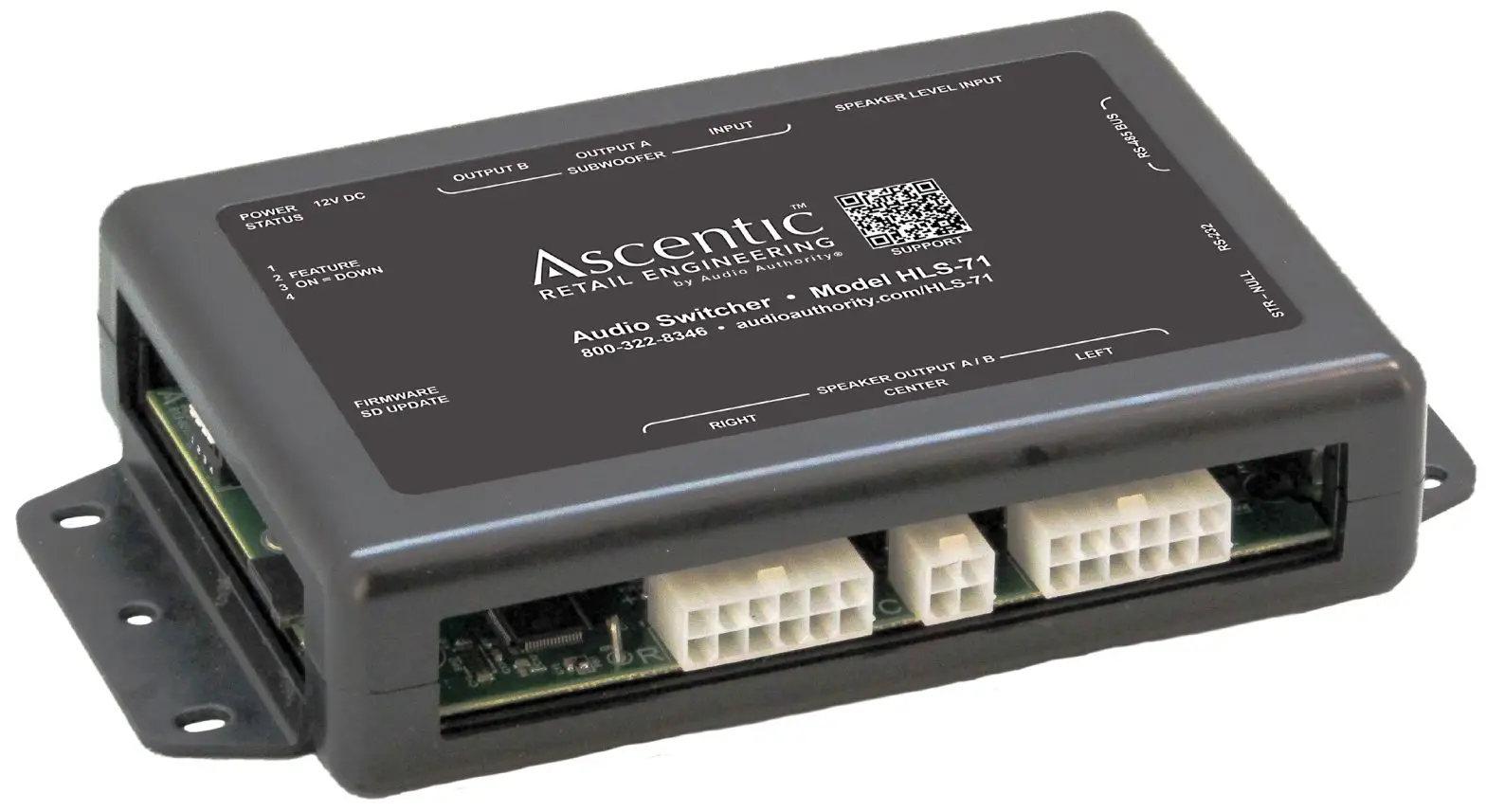
The HLS-71 Intelligent Audio Switcher controls 7.1 channel audio systems between two sets of outputs. This device also monitors system health, with optional network control and monitoring capabilities. The HLS-71 mounts directly to a flat surface using the mounting flanges on the case.
Features
- Switches up to seven channels of High-Level audio and one LFE audio channel between two outputs.
- Measures input voltage, current draw, and peak current draw for device health monitoring.
- Optional IP version (HLS-71-IP) enables remote access to device functions, configuration, and event logs.
- Firmware updated via microSD.
Communication
The HLS-71 Intelligent Audio Switcher has the default device ID 7. It can send and receive serial commands via RS-485 at 57600 Baud, 8-N-1, and half-duplex; and via RS-232 at 115200 Baud, 8-N-1, and full-duplex. Both configuration ports utilize a modular RJ-45 jack with the following pinouts:
RS-485 Pinout:
| Pin # | Function | Pin # | Function |
| P1 | Orange White – Ground | P5 | Blue White – Switched Power Bus (12V Dev Only) |
| P2 | Orange – Ground | P6 | Green – Data B Negative |
| P3 | Green White – Data A Positive | P7 | Brown White – Ground |
| P4 | Blue – Switched Power Bus (12V Devices Only) | P8 | Brown – Ground |
RS-232 Pinout:
| Pin # | Function | Pin # | Function |
| P1 | Orange White – Ground | 135 | |
| P2 | Orange – Ground | P6 | Green – RX or TX |
| P3 | Green White- TX or RX | P7 | Brown White-Ground |
| P4 | P8 | Brown – Ground |
RS-232 Commands
| Commands | Command Format | Response |
| REBOOT | (DEV=7:RE130011 | |
| ANALOGON | (DEV=7:ANALOG=14:0N) | |
| ANALOG OFF | [DEV=7:ANALOG.#: OFF) | |
| RESET DEFAULTS | [DEV=7:RESET: DEFAULT] | |
| GET CURRENT | [DEV=7:CURRENT=11,10W?) | (DEV=7:CURRENT=1:NOW=S) |
| GET MAX CURRENT | [DEV=7:CURRENT=110AX?) | (DEV=7:CURRENT=1:MAX=S) |
| GET MIN CURRENT | [DEV=7:CURRENT=1:MIN?] | (DEV=7:CURRENT=1:MIN=S) |
| RESET CURRENT | [DEV=7:CURRENT=1:RESET] | |
| GET VOLTAGE | [DEV=7:VOLTAGE=1:NOW?] | (DEV=7:VOLTAGE=1:NOW=S) |
| GET MAX VOLTAGE | [DEV=7;VOLTAGE=1:MAX?] | (DEV=7:VOLTAGE=1:MAX=S) |
| GET MIN VOLTAGE | [DEV=7:VOLTAGE= 1:MIN?) | (DEV=7:VOLTAGE=1:MIN=S) |
| RESET VOLTAGE | [DEV=7:VOLTAGE=1;RESET] | |
| APP VERSION | [DEV=7:APP: VERSION?] | (DEV=7:APP: VERSION=S) |
| BOOTLOADER VER | [DEV=7:BOOT: VERSION?) | (DEV=7:BOOT: VERSION=S) |
Quick Start Instructions
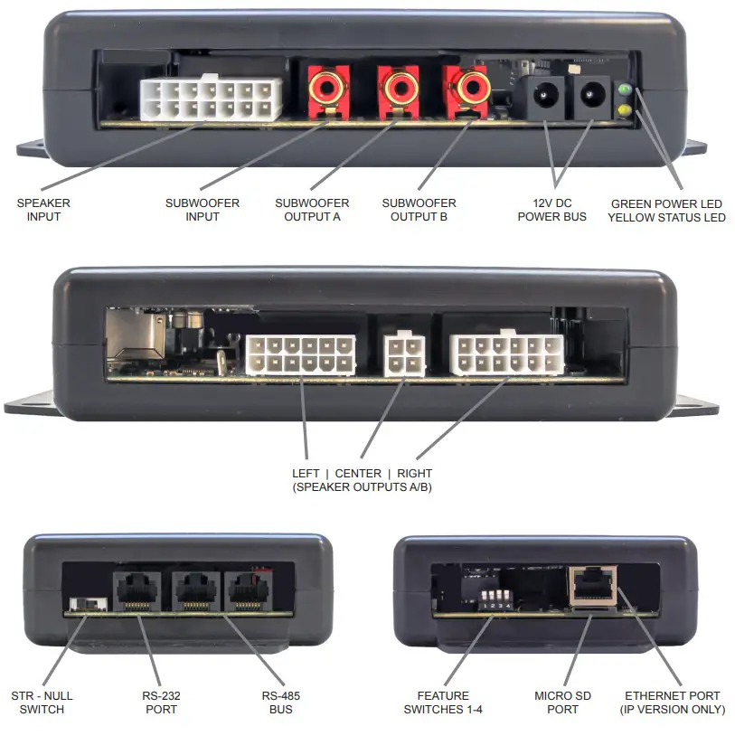
- Connect the receiver harness from “Speaker Level Input” on the HLS device to AVR outputs.
- Connect the speaker harness from the “Left/Right/Center Speaker Output A/B” connections on the HLS device to the appropriate speakers.
- Open a serial terminal – 115200 8-N-1. Toggle Null/Straight switch if needed to correct signal polarity.
- Send analog switch commands to device 7 (default) to enable or disable a position.
Troubleshooting
No RS-232 Communication:
- Ensure connections are fully seated.
- Ensure devices are using the correct protocol settings.
- Ensure the Null/Straight selector is set correctly.
No Ethernet Connectivity (IP version only)
- Ensure connections are fully seated.
- Ensure the end device is powered on with Ethernet enabled.
- Power cycle all devices to clear out previous TCP connections.
Example System:
HLS-71-IP With Speakers and SubwoofersThis display uses audio to attract and communicate. It leverages the HLS-71-IP module’s high-level audio output options to demonstrate two different products. All audio outputs can play either digital or analog audio, depending on the requirements of the device. The Ethernet port interfaces with the network to receive commands and output analytics; with the added capability to control and monitor the system remotely. The HLS-71-IP receives power via an MH2-4K media hub.
Firmware Update Process
The HLS-71 series is updatable through the microSD port utilizing a card with FAT-32 formatting (preferred).Below are the steps outlining the firmware update process:
- Copy new firmware “.FWU” file onto a blank microSD card (FAT-32 format preferred). Insert FirmwareUpdate SD into the device with device power disconnected.
- Apply power to the device, monitoring the power LED Indicator.
- When the power LED indicator returns to a slow blink, the update is complete.
- To verify the firmware update, send the firmware version query listed in the Commands List (see above) and ensure the response matches the firmware version expected.
Power Specification
Power Entry Port: 2x barrel jack connectors (5.5 x 2.1mm, bussed, center positive)Voltage: +12V DCNo-Load Current:HLS-71: 16mAHLS-71-IP: 145mAMaximum Load Current:HLS-71: 175mAHLS-71-IP: 350 mAMaximum Current Output:RS-485 Bus: 1.25 A @ 12.0VDC
Mechanical Details
Case Type: Ascentic universal case, molded ABSCase Dimensions: W x L x H7.5” x 4.1” x 1.5” 190mm x 104mm x 38mmMounting Locations: molded flangesCenterline Holes: 2x 0.165” (4.5mm) diameterSlots: 4x 0.165” x 0.28” (4.5mm x 7mm)1.0” (25.4mm) above/below centerline holes.
report this ad
http://audioauthority.com/HLS-71-IPAscetic is a trademark of Audio Authority Corp.2048 Mercer Road, Lexington, Kentucky 40511-1071800-322-8346 • 859-233-4599 • Fax: 859-233-4510www.audioauthority.com • [email protected]E-21720210120
References
[xyz-ips snippet=”download-snippet”]