
![]()
USER MANUALIpool Net ControllerINTELLIGENT NETWORK CONTROLLERto Control the Pool Technology with Smartphone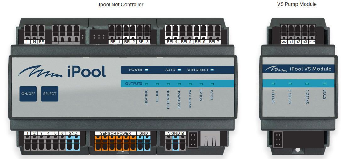
 General Safety Information
This user manual has basic information that should be observed during assembly, start-up, operation, and maintenance. Therefore, this user manual must be read by installers and operators prior to assembly and start/up, and must be accessible to every user of this unit. Additionally, all further safety information in this document absolutely must be observed. Read and follow all instructions. In order to minimise the danger of injury, do not allow children to use this product. Hazards from non-compliance with safety information. Non-compliance with safety information can result in hazards to persons, the environment, and the equipment. Non-compliance with safety information will result in a forfeit of any potential right to damage compensation.
Non-Observance of Safety InstructionsFailure to observe the safety instructions given in this User Manual can result in damage to Device and/or health and property, including environment.Failure to observe the safety instructions and information given in this User Manual shall result in exclusion or restriction of the prospective right to compensation for damage.
Insufficient Qualification of Person Using the DeviceHazards in the event of insufficiently qualified personnel, potential consequence: Injury, heavy material damage.
- The system operator must ensure compliance with the required qualification level.
- Any and all work may only be performed by correspondingly qualified personnel.
- Access to the system must be prevented for insufficiently qualified persons, e.g. via access codes and passwords.
Non-compliance with informational textThere is a great deal of informational text indicating hazards and their avoidance. Not observing informational text may lead to hazards. Potential consequence: gravest degree of injury, heavy material damage.
- Read all informational text carefully.
- Cancel the process if you are unable to exclude all potential hazards.
Use of Device New FunctionsBecause of the continued development, a Ipool Net Controller® unit may contain functions, which are not completely described in this version of the user manual. The use of such new or extended functions without a profound and secure understanding by the operator may result in malfunctions and severe problems. Potential consequence: Injury, heavy material damage.
- Make sure to get a profound and secure understanding of a function and relevant boundary conditions, before you start to use it.
- Check for an updated version of the user manual or additional documentation available for the relevant functions.
- Make use of the integrated help function of the Ipool Net Controller® to get detailed information on functions and their parameter settings.
- In case it should not be possible to get a profound and secure understanding of a function based on the available documentation, do not use this function.
Conditions to be Met before You Start Using DeviceMake sure you have a newest and updated version of the user manual and other documentation for all functions of the unit. Use and read the integrated help features. In case of not understanding the information about certain features of the unit, do not use these features.
Box Content
| Power supply | 110-240 VAC / 50 Hz / 60 Hz |
| Input power | 10 VA |
| Overvoltage category | II |
| Protection degree | IP30 |
| Climatic resistance | +5 to +40°C |
| Weight | 800 g |
| Installation | wall DIN rail mounting |
| Relay output contacts | max 230 V / 1 A, potential free contact – NO |
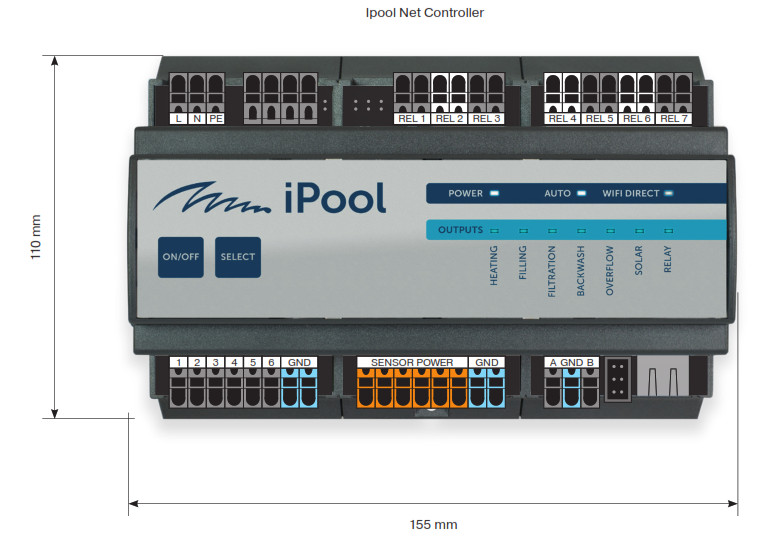
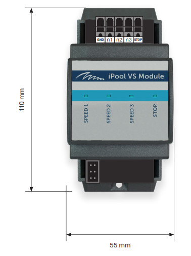
| Dimensions | 155 x 110 x 60 mm and 55 x 110 x 60 mm |
| Sensor power supply | 6 x 18 VDC / max 50mA |
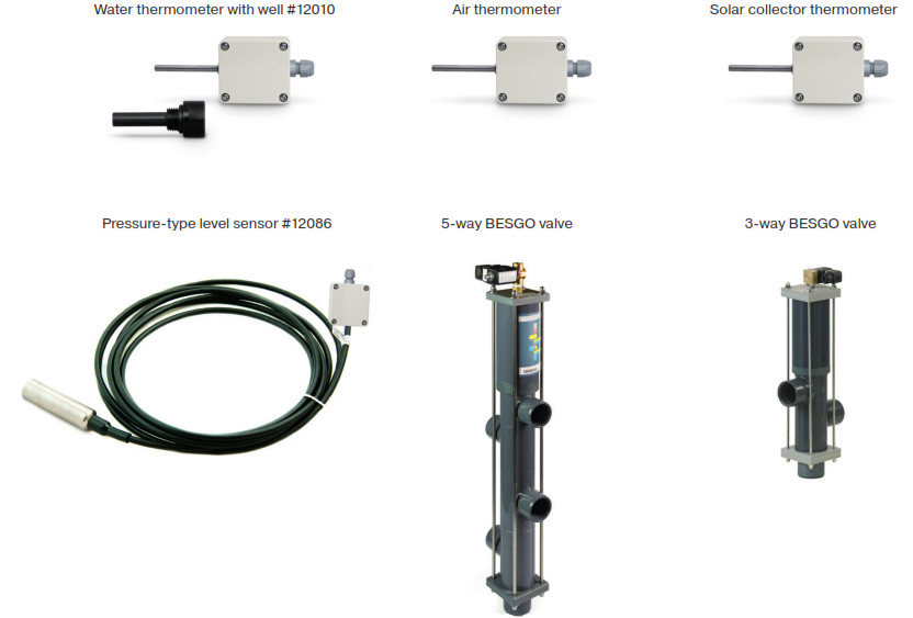
Accessories Available for Purchase
Ipool Net Controller
The network controller to control the pool technology. The Ipool Net Controller network controller is able to control and adjust all the pool technology elements. The Ipool Net Controller can be adjusted and controlled by means of the perfectly designed user-friendly application via the internet. In case of an internet failure, it is possible to establish connection to the controller directly through the WIFI Direct. The Ipool Net Controller is intended for the DIN rail mounting directly into the switchboard.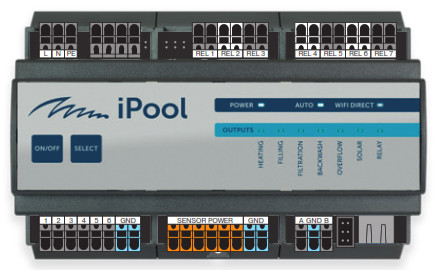
Basic Functions.
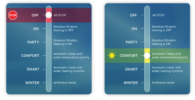
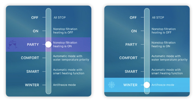
The Ipool Net Controller has capacity for 6 preset basic pool operation modes.
![]() OFF All is switched off.
OFF All is switched off.
![]() ON The circulating pump is switched on at speed 2 (variable pumps can be set to 3 speeds) and heating switched off.
ON The circulating pump is switched on at speed 2 (variable pumps can be set to 3 speeds) and heating switched off.
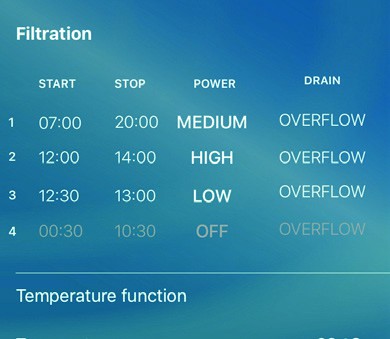
![]() COMFORT This mode is intended for routine pool operation when the priority is to achieve the required temperature. This mode alow to preset four filtering periods in the day when you can preset the pumping power and select if to use the overflow or the bottom drainage.
COMFORT This mode is intended for routine pool operation when the priority is to achieve the required temperature. This mode alow to preset four filtering periods in the day when you can preset the pumping power and select if to use the overflow or the bottom drainage.
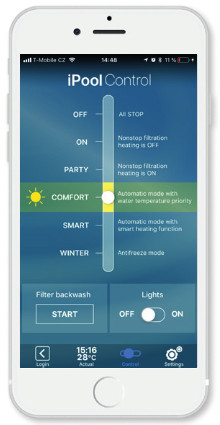
![]() PARTY This mode switches the circulating pump at the speed 2 and heating the required temperature. This mode has no time functions.
PARTY This mode switches the circulating pump at the speed 2 and heating the required temperature. This mode has no time functions.![]() SMART The same as COMFORT mode together with SMART Heating function.
SMART The same as COMFORT mode together with SMART Heating function.![]() WINTER To enable this function is necessary to install the outdoor thermometer.
WINTER To enable this function is necessary to install the outdoor thermometer.
- If outdoor temperature drops below 0 °C the circulating pump is switched on.
- After 15 minutes system check the water temperature .
- If the water temperature is still below the preset freezing temperature (e.g. 4 °C), the relay switchesthe heating on.
- After the preset temperature is reached, the circulating pump stops. Next test of pool temperature and the circulating pump start will follow in 6 hours.
Terminal Board
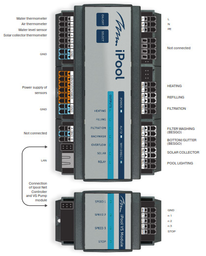
Electrical Connection
Control and Settings
Manual Button OperationFor easier installation and necessary events…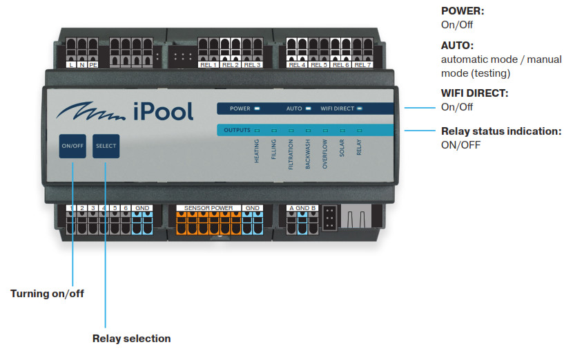
Initial startIpool Net Controller will turn to standard operating mode SMART with factory settings after the initial connection of power supply. After repeated switching on the unit continue in the original mode preset by user.LED Power shines signalize connected power supplyLED Power does not shine the power supply is disconnectedLED Auto shines Ipool Net Controller works in standard operating mode with automatic control.LED Auto does not shine Ipool Net Controller works in manual modeLED WiFi shines signalize WiFidirect network is ON.LED WiFi blinks to wifidirect is connected acting user. At this case are commands from mobile application connected by wifidirect in priority to LAN connection event he LAN connection is available.
Manual modeIt is possible to use buttons at the front panel of Ipool Net Controller for simple control in testing operation when necessary to check function of connected components or in extreme cases when there is no available connection to Ipool Net Controller by application.Press the button ON/OFF for switching the Ipool Net Controller off or on. Ipool Net Controller switches all outputs off and after switching on will continue in the preset mode.Press the SELECT button to enter the manual mode. Ipool Net Controller will switch off all outputs and blue LED at the (HEATING) output start blinking. You can switch on or off the selected output by pressing SELECT button and move to next output. This way you can switch on or off all outputs. There will not blink any blue LED after eighth press of SELECT button and you can leave Ipool Net Controller or in manual mode or by pressing ON/OFF button return to automatic mode.
Control with iPool Control Application
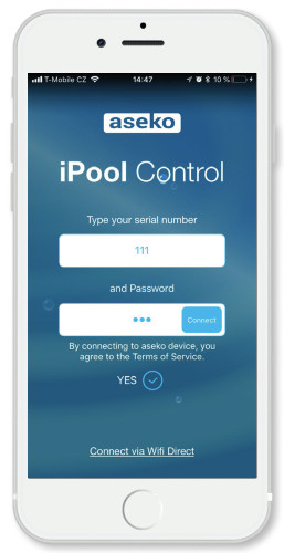 iPool Control InstallationInstall the iPool Control application from App Store on iOS device.Prior to the first connection to the Ipool Net Controller, confirm your acceptance of “Ipool Net Controller Terms and Conditions”.Serial numberEnter the serial number of your Ipool Net Controller.PasswordWhen signing in for the first time, choose a password you will use. Ipool Net Controller will remember the password. From this moment use the serial number and this password to log in to your Ipool Net Controller.E-mailProvide a valid e-mail address to which you have access. E-mail address serves to remind the forgotten password.Forgotten passwordTo recover a forgotten password, click for reminding the password.Connecting via Wifi DirectTo connect to Ipool Net Controller via Wifi Direct, you must be within range of the Ipool Net Controller internal antenna (approx. 3 m).Click “Connect via Wifi Direct” to open the iPool Connect window.Click on ,,Go to settings Wifi”.A list of Wifi networks will show up, find your Ipool Net Controller serial number, select it and connect. Return to the iPool Control application.
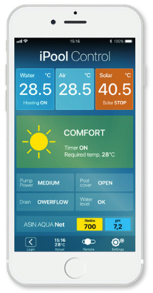
Current status
The screen provides all the important information about the current status of your pool and the connected components controlled by Ipool Net Controller.
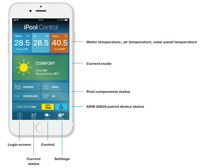
Control
The screen serves to switch between operation modes of your pool controlled via Ipool Net Controller.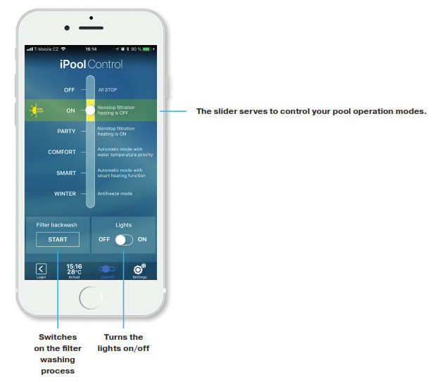

Settings
The screen serves to set the Ipool Net Controller and characteristic of each mode including the filtration timer.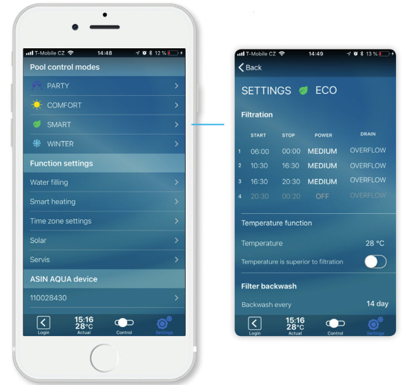

SMART Heating
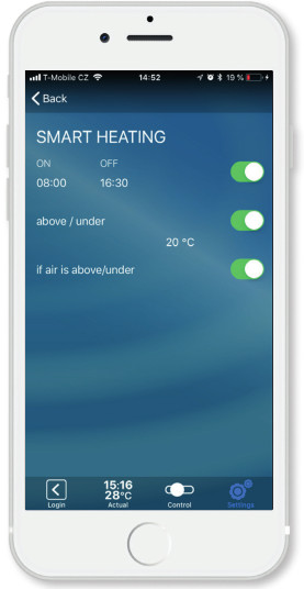 Heating Time AdjustmentThis function allows to adjust time of heating operation. This is particularly useful for switching on the heat pumps that have higher efficiency during the day time when outdoor temperature is higher.
Adjustment of Temperature above/below which Heating is in OperationThis function allow you to customize the pool heating and achieve the highest possible efficiency of the heat pump. “I heat just when the outdoor. temperature is higher than ……, or I heat just till the outdoor temperature reaches …… .” The high-accuracy electronic thermometer is used for water temperature measurement. It should be installed to the inlet pipe comming from the pool. Never install it downstream of the heat exchanger. Significant distortion of temperature would occur. When temperature drops below the required value, the relay No. 1 switches on the heat source (heat pump, electric heating, gas boiler circulating pump).
Temperature Control Takes Priority over Filtration ControlIf you select the temperature control to take priority over the filtration timer, heating, as well as the circulating pump, will be in operation even after the adjusted time of filtering. The circulation pump will stop after the required temperature is achieved. It will restart at next preset period of the timer.
Measuring the level and Automatic water Refilling
The water level is measured by the pressure-dependent level sensor. This allows very easy installation by inserting the sensor into the storage reservoir or skimmer. Water Level is controlled at four adjustable height levels that are easily entered in centimetres. The level sensor cable must not be broken anywhere in order to prevent the balancing tube that is a part of the cable from being clogged.
OVER – too much water in the overflow tank
When this level is reached:
- The circulating pump starts
- If the automatic filter washing is enabled, one filter washing cycle starts.OK – required level Refilling stopsON – level at which pool refilling starts after 10 seconds during which the level is permanently below this value in order to prevent oscillatingSmall amount of water
The circulating pump, as well as heating, will be disabledMaximum Refilling TimeThe maximum refilling time acts as protection for case of any failure of the level measuring. This function will switch off the pool refilling after the adjusted time has elapsed regardless of a level sensor signal.
Automatic Filter Washing
 Automatic Filter Washing
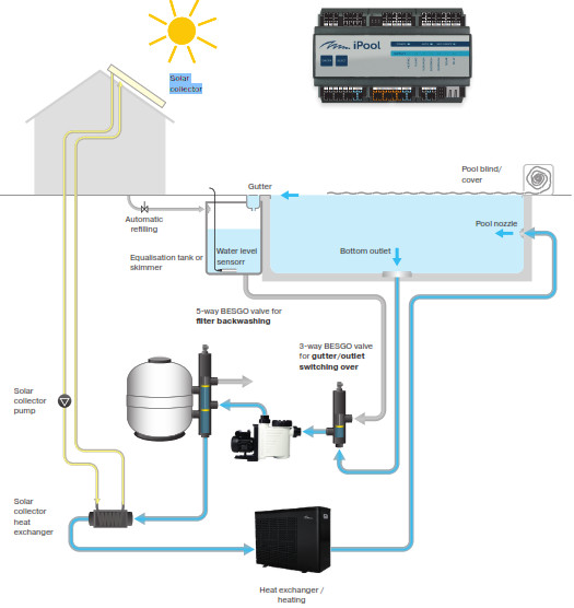
The automatic washing function ensures the filter washing on a regular basis in the preselected intervals. To enable this function is necessary to use the automatic 5-way BESGO valve. Its moving controlled by the relay No. 4 switching on/off. When the relay switches on, the BESGO valve is activated and moved to the required position by the action of pressure water or air. See the BESGO manual.
 Overflow/Bottom Switching OverTo use this function, it is necessary to install the 3-way BESGO switching-over valve. It is possible to make a decision whether water shall circulate through the overflow or the bottom drainage. If a closed blind control signal appears at the (logic) input No. 5, the relay No. 5 closes and the overflow is switched over to the bottom drainage.
 Variable-speed Pump ControlThe Ipool Net Controller with the additional ASIN Pump module enable to control the circulating pumps with a SPECK and PENTAIR variable drive. Power of such pump (1 or 2) can be selected at preset periods in individual modes. In case of backwashing, the pump is running at speed 3. Individual speeds 1, 2, 3 are adjusted directly on the pump according to the respective pump manual.
Solar
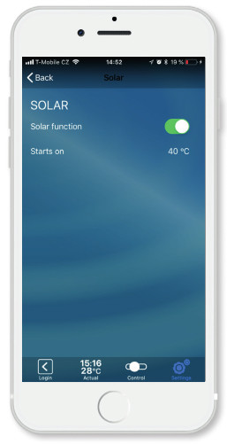 Solar
SolarThe Ipool Net Controller allows control of the solar heating. To enable this function is necessary to install the outdoor thermometer to the solar collector. At the preset temperature of the solar collector, e.g. 40°C will solar system circulating pump (relay No. 6) as well as the filter pump start on. This start takes absolute priority over other settings in order to prevent the solar collector from being overheated.
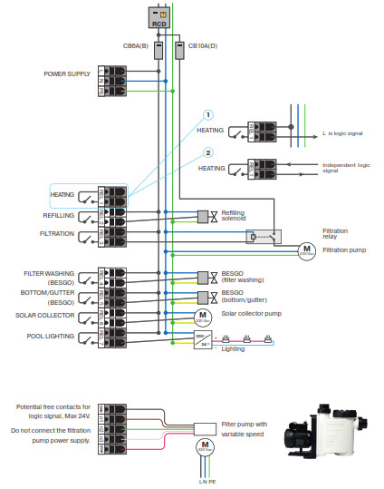
Installation
Controller Ipool Net Controller is to be installed to switchboard or wall-mounted box at DIN-Rail 35 mm. Diagram of terminal blocks and wiring is below. Provide connection and wiring only in if the unit is switched OFF or disconnected from power supply! Wiring of relay outputs may be realized by wire with maximum of 2,5 mm2. Maximum relay load is 230 V AC / 1A. Power supply cable by CYKY 2×1,5 should be equipped by single pole circuit breaker 6A/250V, characteristic B signed as Ipool Net Controller. Do not forget to add suitable current protector, for example, 16A(B)/30mA.
Maintenance
Controller system and connected sensors does not require any special maintenance. Protect all vent outlets against overlapping.
Safety
Connection of power supply must be provided by person with corresponding qualification. Opening the unit cover or change of any components of the unit is prohibited.
Servis
In case of need any additional info or service, contact the manufacturer:ASEKO, spol. s r.o.Vídeská 340, Vestec u Prahy, 252 50IC: 40766471, DIC: CZ40766471Telefon: +420 244 912 210, +420 603 500 940E-mail: [email protected]
References
[xyz-ips snippet=”download-snippet”]