
ASR DBO433 Differential Barometer/Altimeter OEM Module User Manual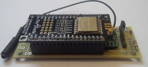
Features
- Integrated MCU
- Corrected atmospheric pressure readings
- Derived elevations with customizable datum
- Multi-node capable
- Simple serial interface
- Metric or Imperial output units
Application Examples
- Indoor elevations
- Building pressurization monitoring
- Multi-node telemetry networks
- Altitude reference for UAVs
Overview
The DBOxxx series differential barometer/altimeter (patent pending) OEM module provides atmospheric pressures and derived elevations at a rover using corrections transmitted from a stationary base. In traditional systems elevations are calculated based on pressure readings for a stand alone unit and are subject to the errors inherent with environmental changes in pressure. This versatile engine offers three modes of operation detailed below.
Modes
A) Determining a floating rover elevations based on corrections (black arrow) from a fixed base. In this application the rover outputs a corrected elevation as it is raised or lowered relative to the ambient atmospheric pressure (blue arrows). When used inside an enclosed space such as a building both units must be located within. Multiple rovers can use the same base.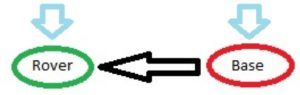
B) Determining a fixed rover pressure difference based on corrections (black arrow) from a fixed base. In this application the rover outputs a corrected pressure (grey arrow) inside an enclosed space such as a building (grey rectangle) relative to the ambient atmospheric pressure (blue arrows). The base must be located outside the enclosed space. Multiple rovers can use the same base.
C) Multi-node telemetry. In this application the rover receives remote uncorrected pressures and temperatures from multiple bases. The pressure data is absolute and not differentially corrected.
Specifications
- Differential Pressure Accuracy: +/- 0.041 mbar (+/- 36cm) RMS
- Absolute Pressure Accuracy: +/- 1.5 mbar
- Temperature Accuracy: +/- 0.8C @ 25C
- Operating Temperature: -20C to 70C
- Current (base): 10-60mA peak @ 5VDC (DBO433/DBO915), 10-75mA peak @ 5VDC (DBO868)
- Current (rover): 20mA @ 5VDC
- Dimensions (L x W x H): 82mm x 32mm x 18mm
- Range: 1Km (DBO433/DBO915), 5Km (DBO868)
- Voltage: 3.8 – 15 VDC
- Weight: 30g
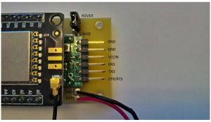
Pinout
| Pin | Description |
| ROVER | Rover mode jumper selection |
| BASE | Base mode jumper selection |
| GND | Ground |
| VCCIN | Regulated supply (3.3 VDC) |
| RXD | Serial data in |
| TXD | Serial data out |
| DTR/RTS | Serial flow control |
| BAT+ | Battery supply (3.8 – 15 VDC) |
Serial communication parameters are 9600bps (N,8,1). The DTR/RTS signal pin is only required to update the firmware.
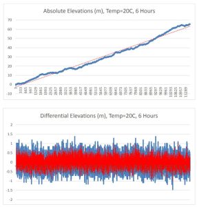
Typical Characteristics
Modules were stationary for testing at a set fixed datum elevation of 0m.
Commands
The general command syntax is command,{x{,y}} followed by CR+LF.
| Command | Description |
| 1,x | Set NetID, both base and rover must match. Valid range is x=0 to 999. |
| 2,x | Set NodeID, every NodeID on NetID must be unique. Valid range is x=0 to 999. |
| 3,x | Set Units. Metric x=0 (mb,m, C), Imperial x=1 (inHg,ft, F)). |
| 4,x,y | Average Elevation Datum and Base NodeID (differential mode preset, rover only). Valid Elevation Datum range is x=-9999.99 to 9999.99. Valid Base NodeID range is y=0 to 999 |
| 5 | Set Elevation Datum and Base NodeID from 4 (differential mode , rover only) |
| 6 | Clear Elevation Datum (absolute mode, rover only). |
| 7, x | Set inverse elevations (differential mode, rover only). Disabled x=0 (default), Enabled x=1. |
Output
On initialization the unit will send the string ASR DBOxxx v y.y where:
- xxx: model number (433,868 or 915 MHz)
- y.y: firmware revision number
Base output format is as follows:
- NetID,NodeID,B,Units,Local Pressure, Local Elevation, Local Temperature*Checksum
Rover output (absolute mode default) format is as follows:
- NetID,NodeID,R,Units,Local Pressure, Local Elevation, Local Temperature*Checksum
Rover output (available base telemetry) format is as follows:
- NetID,BaseNodeID,T,Units,Remote Pressure, Remote Elevation, Remote Temperature*Checksum
Rover output (differential mode) format is as follows, output will be ,A, (preset) until set:
- Pressure,Pressure Residual, Local Elevation, Remote Elevation, Local Elevation Datum,Differential Elevation, Elevation Residual, Local Temperature,Remote Temperature *Checksum.Checksum is a hex value calculated by applying XOR on each character in the string up to but not including the asterix.
Base NodeID must be an available node in the rover telemetry stream output for commands 4 and 5 to output differential results.
Command 7,1 is used to inverse the differential elevations at the rover when the base is moving relative to a stationary rover in mode A. When enabled the BaseNodeID in the differential output will be preceded by a negative sign. Sending 7,0 will set the module back to noninversed output (default). This would be useful in an application such as an altitude reference for a UAV where the base is onboard and transmitting results to a stationary rover on the ground.
Setup
The following is the initial setup procedure:
- Select BASE jumper position on base.
- Send 1,NetID to base.
- Send 2,NodeID to base.
- Select ROVER jumper position on rover.
- Send 1,NetID to rover.
- Send 2,NodeID to rover.
- Send 3,Units to rover.
- Send 4,Elevation Datum,Base NodeID to rover.
- Send 5, to rover (once datum residuals are acceptable in step 8).
NetID, NodeID and Units settings are persistent and will be retained when power cycled. Only steps 8-9 above are required for a differential solution on subsequent power-ups.
Do not move the modules during the calibration in step 8.
Demo Software
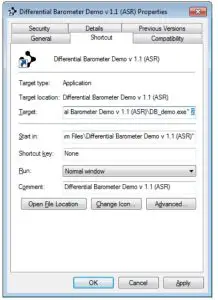
The Differential Barometer Demo software is available for download on our website at https://www.asr-web.com/support and allows users to evaluate the capabilities of the system. The DB_demo.exe file is invoked with a single parameter which specifies the serial port number to use. After installation right-click the shortcut and select “Properties”, under the “Shortcut” tab enter the port number after the “Target” path as highlighted below then click the “OK” button. In Windows 10 click and drag the shortcut to the desktop first.
When connected to the base, pressure and elevation graphs are absolute readings. Only the base temperature is displayed in this mode. The range corresponding to 0 on the graphs is shown in brackets in each title. The left buttons on the bottom left will be labeled “NetID (x)” where x is the current NetID and “NodeID (y)” where y is the current NodeID . To set a new NetID or NodeID enter it into the corresponding text box and click the button. The current Unitscan be changed on the bottom. In this mode the “Datum” button and “ NodeID” combo boxes are disabled. The “Reset” button the right will clear the graphs.
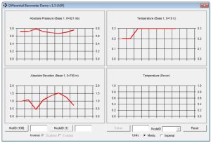
When connected to the rover, pressure and elevation graphs are absolute readings until a datum is set. Only the rover temperature is displayed in this mode. The range corresponding to 0 on the graphs is shown in brackets in each title. The left buttons on the bottom left will be labeled “NetID (x)” where x is the current NetID and “NodeID (y)” where y is the current NodeID. To set a new NetID or NodeID enter it into the corresponding text box and click the button. The current Units can be changed on the bottom. In this mode the “Datum” button and “NodeID” combo boxes on the bottom right are disabled until base telemetry is received on the same NetID. The “Reset” button to the right will clear the graphs.
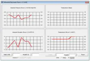
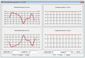
When base telemetry is available the “Datum” button and “NodeID” combo box on the bottom right will become enabled. Absolute readings for available base telemetry can be viewed by choosing the Base NodeID using the “NodeID” combo box. To set the Elevation Datum enter it into the text box and click the “Datum” button. After the “Datum” button is clicked it will change to “Adjust (x)” where x is the current Elevation Residual as an average deviation from the preset datum, do not move the units during the calibration. To set the Elevation Datum click the “Adjust (x)” button and the label will change to “Datum (y)” where y is the current Elevation Datum and differential data will be displayed. In this mode both base and rover temperatures are displayed.
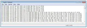
A log.txt file in the application directory stores the output with a date/time stamp.
Firmware Updates
Firmware updates are available for download on our website at https://www.asrweb.com/support.
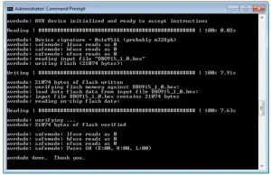
The following is the firmware update procedure:
- Connect the OEM module to a USB-serial converter, the DSR/DTR line must be used.
- Connect USB-serial converter to a port on your local machine.
- Unzip the package.
- Launch a command window.
- Change the directory to the location of the package.
- Invoke update.bat with a single parameter which specifies the serial port number to use.
References
[xyz-ips snippet=”download-snippet”]