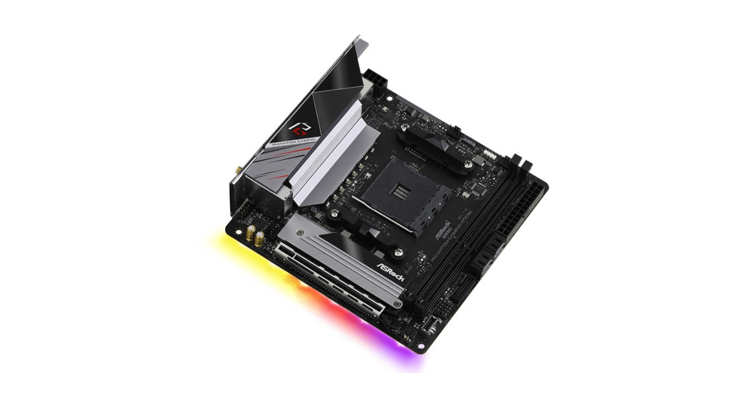
Phantom Gaming-ITX/ax B550
Version 1.0 Published May 2020 Copyright©2020 ASRock INC. All rights reserved.Copyright Notice:No part of this documentation may be reproduced, transcribed, transmitted, or translated in any language, in any form or by any means, except duplication of documentation by the purchaser for backup purpose, without written consent of ASRock Inc.Products and corporate names appearing in this documentation may or may not be registered trademarks or copyrights of their respective companies, and are used only for identification or explanation and to the owners’ benefit, without intent to infringe.Disclaimer:Specifications and information contained in this documentation are furnished for informational use only and subject to change without notice, and should not be constructed as a commitment by ASRock. ASRock assumes no responsibility for any errors or omissions that may appear in this documentation.With respect to the contents of this documentation, ASRock does not provide warranty of any kind, either expressed or implied, including but not limited to the implied warranties or conditions of merchantability or fitness for a particular purpose.In no event shall ASRock, its directors, officers, employees, or agents be liable for any indirect, special, incidental, or consequential damages (including damages for loss of profits, loss of business, loss of data, interruption of business and the like), even if ASRock has been advised of the possibility of such damages arising from any defect or error in the documentation or product.This device complies with Part 15 of the FCC Rules. Operation is subject to the following two conditions: (1) this device may not cause harmful interference, and (2) this device must accept any interference received, including interference thatmay cause undesired operation.CALIFORNIA, USA ONLYThe Lithium battery adopted on this motherboard contains Perchlorate, a toxic substance controlled in Perchlorate Best Management Practices (BMP) regulations passed by the California Legislature. When you discard the Lithium battery in California, USA, please follow the related regulations in advance. “Perchlorate Material-special handling may apply, see www.dtsc.ca.gov/hazardouswaste/ perchlorate”ASRock Website: http://www.asrock.com
AUSTRALIA ONLYOur goods come with guarantees that cannot be excluded under the Australian Consumer Law. You are entitled to a replacement or refund for a major failure and compensation for any other reasonably foreseeable loss or damage caused by our goods. You are also entitled to have the goods repaired or replaced if the goods fail to be of acceptable quality and the failure does not amount to a major failure. If you require assistance please call ASRock Tel : +886-2-28965588 ext.123 (Standard International call charges apply)The terms HDMI® and HDMI High-Definition Multimedia Interface, and the HDMI logo are trademarks or registered trademarks of HDMI Licensing LLC in the United States and other countries.
CE WarningThis device complies with directive 2014/53/EU issued by the Commision of the European Community. This equipment complies with EU radiation exposure limits set forth for an uncontrolled environment. This equipment should be installed and operated with minimum distance 20cm between the radiator & your body.Operations in the 5.15-5.35GHz band are restricted to indoor usage only.
Radio transmit power per transceiver type
Function WiFiBluetooth
Frequency 2400-2483.5 MHz 5150-5250 MHz 5250-5350 MHz5470-5725 MHz 2400-2483.5 MHz
Maximum Output Power (EIRP)18.5 + / -1.5 dbm 21.5 + / -1.5 dbm 18.5 + / -1.5 dbm (no TPC) 21.5 + / -1.5 dbm (TPC) 25.5 + / -1.5 dbm (no TPC) 28.5 + / -1.5 dbm (TPC) 8.5 + / -1.5 dbm
Contents
Chapter 1 Introduction
1
1.1 Package Contents
1
1.2 Specifications
2
1.3 Motherboard Layout
7
1.4 I/O Panel
10
1.5 WiFi-802.11ax Module and ASRock WiFi 2.4/5 GHz Antenna 11
Chapter 2 Installation
12
2.1 Installing the CPU
13
2.2 Installing the CPU Fan and Heatsink
15
2.3 Installing Memory Modules (DIMM)
23
2.4 Expansion Slots (PCI Express Slots)
25
2.5 Jumpers Setup
26
2.6 Onboard Headers and Connectors
27
2.7 M.2_SSD (NGFF) Module Installation Guide (M2_1)
32
2.8 M.2_SSD (NGFF) Module Installation Guide
35
Chapter 3 Software and Utilities Operation
38
3.1 Installing Drivers
38
3.2 ASRock Motherboard Utility (Phantom Gaming Tuning)
39
3.2.1 Installing ASRock Motherboard Utility (APhantom Gaming
Tuning)
39
3.2.2 Using ASRock Motherboard Utility (Phantom Gaming Tuning)39
3.3 ASRock Live Update & APP Shop
42
3.3.1 UI Overview
42
3.3.2 Apps
43
3.3.3 BIOS & Drivers
46
3.3.4 Setting
47
3.4 Nahimic Audio
48
3.5 ASRock Polychrome SYNC
49
Chapter 4 UEFI SETUP UTILITY
52
4.1 Introduction
52
4.1.1 UEFI Menu Bar
52
4.1.2 Navigation Keys
53
4.2 Main Screen
54
4.3 OC Tweaker Screen
55
4.4 Advanced Screen
59
4.4.1 CPU Configuration
60
4.4.2 Onboard Devices Configuration
61
4.4.3 Storage Configuration
63
4.4.4 ACPI Configuration
64
4.4.5 Trusted Computing
65
4.4.6 AMD PBS
66
4.4.7 AMD Overclocking
67
4.4.8 AMD CBS
68
4.5 Tools
69
4.6 Hardware Health Event Monitoring Screen
70
4.7 Security Screen
72
4.8 Boot Screen
73
4.9 Exit Screen
76
B550 Phantom Gaming-ITX/axChapter 1 IntroductionThank you for purchasing ASRock B550 Phantom Gaming-ITX/ax motherboard, a reliable motherboard produced under ASRock’s consistently stringent quality control. It delivers excellent performance with robust design conforming to ASRock’s commitment to quality and endurance. In this documentation, Chapter 1 and 2 contains the introduction of the motherboard and step-by-step installation guides. Chapter 3 contains the operation guide of the software and utilities. Chapter 4 contains the configuration guide of the BIOS setup.Because the motherboard specifications and the BIOS software might be updated, the content of this documentation will be subject to change without notice. In case any modifications of this documentation occur, the updated version will be available on ASRock’s website without further notice. If you require technical support related to this motherboard, please visit our website for specific information about the model you are using. You may find the latest VGA cards and CPU support list on ASRock’s website as well. ASRock website http://www.asrock.com.1.1 Package Contents· ASRock B550 Phantom Gaming-ITX/ax Motherboard (Mini-ITX Form Factor) · ASRock B550 Phantom Gaming-ITX/ax Quick Installation Guide · ASRock B550 Phantom Gaming-ITX/ax Support CD · 2 x Serial ATA (SATA) Data Cables (Optional) · 1 x Screw for M.2 Socket (Optional) · 1 x ASRock WiFi 2.4/5 GHz Antenna (Optional)1
English
1.2 Specifications
Platform
· Mini-ITX Form Factor · 8 Layer PCB · 2oz Copper PCB
CPU
· Supports 3rd Gen AMD AM4 RyzenTM / future AMD RyzenTM Processors (3000 and 4000 Series Processors)** Not compatible with AMD RyzenTM 5 3400G and RyzenTM 33200G. · Digi Power design · 8 Power Phase design
Chipset
· AMD B550
Memory
· Dual Channel DDR4 Memory Technology · 2 x DDR4 DIMM Slots · AMD Ryzen series CPUs (Matisse) support DDR4 4733+(OC)/4666(OC)/4600(OC)/4533(OC)/4466(OC)/4400 (OC)/4333(OC)/4266(OC)/4200(OC)/4133(OC)/4000 (OC)/3866(OC)/3800(OC)/3733(OC)/3600(OC)/3466 (OC)/3200/2933/2667/2400/2133 ECC & non-ECC, unbuffered memory* · AMD Ryzen series APUs (Renoir) support DDR4 4733+ (OC)/4666(OC)/4600(OC)/4533(OC)/4466(OC)/4400 (OC)/4333(OC)/4266(OC)/4200(OC)/4133(OC)/4000 (OC)/3866(OC)/3800(OC)/3733(OC)/3600(OC)/3466 (OC)/3200/2933/2667/2400/2133 ECC & non-ECC, unbuffered memory* * Please refer to Memory Support List on ASRock’s website for more information. (http://www.asrock.com/) * Please refer to page 23 for DDR4 UDIMM maximum frequency support. · Max. capacity of system memory: 64GB · Supports Extreme Memory Profile (XMP) memory modules · 15 Gold Contact in DIMM Slots
English
2
B550 Phantom Gaming-ITX/ax
Expansion Slot
AMD Ryzen series CPUs (Matisse) · 1 x PCI Express x16 Slot (PCIE1: Gen4x16 mode)* AMD Ryzen series APUs (Renoir) · 1 x PCI Express x16 Slot (PCIE1: Gen3x16 mode)* * Supports NVMe SSD as boot disks · 1 x Vertical M.2 Socket (Key E) with the bundled WiFi-802.11ax module (on the rear I/O) · 15 Gold Contact in VGA PCIe Slot (PCIE1)
Graphics
· Integrated AMD RadeonTM Vega Series Graphics in Ryzen Series APU** Actual support may vary by CPU · DirectX 12, Pixel Shader 5.0 · Shared memory default 2GB. Max Shared memory supportsup to 16GB.* The Max shared memory 16GB requires 32GB system memoryinstalled. · Dual graphics output: support HDMI and DisplayPort 1.4ports by independent display controllers · Supports HDMI 2.1 with max. resolution up to 4K x 2K(4096×2160) @ 60Hz · Supports DisplayPort 1.4 with max. resolution up to 5K(5120×2880)@120Hz · Supports Auto Lip Sync, Deep Color (12bpc), xvYCC andHBR (High Bit Rate Audio) with HDMI 2.1 Port (CompliantHDMI monitor is required) · Supports HDR (High Dynamic Range) with HDMI 2.1 · Supports HDCP 2.3 with HDMI 2.1 and DisplayPort 1.4Ports · Supports 4K Ultra HD (UHD) playback with HDMI 2.1 andDisplayPort 1.4 Ports · Supports Microsoft PlayReady®
Audio
· 7.1 CH HD Audio with Content Protection (RealtekALC1220 Audio Codec) · Premium Blu-ray Audio support · Supports Surge Protection · 120dB SNR DAC with Differential Amplifier · Pure Power-In · Direct Drive Technology
3
English
· PCB Isolate Shielding · Impedance Sensing on Rear Out port · Individual PCB Layers for R/L Audio Channel · 15 Gold Audio Connector · Nahimic Audio
LAN
· 2.5 Gigabit LAN 10/100/1000/2500 Mb/s · GigaLAN Intel® I225V · Supports Wake-On-LAN · Supports Lightning/ESD Protection · Supports Energy Efficient Ethernet 802.3az · Supports PXE
Wireless LAN
· Intel® 802.11ax WiFi Module · Supports IEEE 802.11a/b/g/n/ax · Supports Dual-Band (2.4/5 GHz) · Supports WiFi6 802.11ax (2.4Gbps) · 2 antennas to support 2 (Transmit) x 2 (Receive) diversitytechnology · Supports Bluetooth 5.1 + High speed class II · Supports MU-MIMO
Rear Panel I/O
· 2 x Antenna Ports · 1 x HDMI Port · 1 x DisplayPort 1.4 · 1 x USB 3.2 Gen2 Type-A Port (10 Gb/s) (Supports ESDProtection) · 1 x USB 3.2 Gen2 Type-C Port (10 Gb/s) (Supports ESDProtection) · 4 x USB 3.2 Gen1 Ports (Supports ESD Protection) · 1 x RJ-45 LAN Port with LED (ACT/LINK LED and SPEEDLED) · HD Audio Jacks: Line in / Front Speaker / Microphone
English
Storage
· 4 x SATA3 6.0 Gb/s Connectors, support RAID (RAID 0, RAID 1 and RAID 10), NCQ, AHCI and Hot Plug· 1 x Hyper M.2 Socket (M2_1), supports M Key type 2280 M.2 PCI Express module up to Gen4x4 (64 Gb/s) (with Matisse) or Gen3x4 (32 Gb/s) (with Renoir)*
4
B550 Phantom Gaming-ITX/ax
· 1 x M.2 Socket, supports M Key type 2280 M.2 SATA3 6.0 Gb/s module and M.2 PCI Express module up to Gen3 x4 (32 Gb/s)** Supports NVMe SSD as boot disks * Supports ASRock U.2 Kit (M2_1)
Connector
· 1 x RGB LED Header * Supports in total up to 12V/3A, 36W LED Strip · 1 x Addressable LED Header * Supports in total up to 5V/3A, 15W LED Strip · 1 x CPU Fan Connector (4-pin) * The CPU Fan Connector supports the CPU fan of maximum 1A (12W) fan power. · 1 x CPU/Water Pump Fan Connector (4-pin) (Smart FanSpeed Control) · 1 x Chassis/Water Pump Fan Connector (4-pin) (Smart FanSpeed Control) * The Chassis/Water Pump Fan supports the water cooler fan of maximum 2A (24W) fan power. * CPU_FAN2/WP and CHA_FAN1/WP can auto detect if 3-pin or 4-pin fan is in use. · 1 x 24 pin ATX Power Connector (Hi-Density Power Con-nector) · 1 x 8 pin 12V Power Connector (Hi-Density Power Connec-tor) · 1 x Front Panel Audio Connector (15 Gold Audio Connec-tor) · 1 x USB 2.0 Header (Supports 2 USB 2.0 ports) (SupportsESD Protection) · 1 x USB 3.2 Gen1 Header (Supports 2 USB 3.2 Gen1 ports)(Supports ESD Protection) · 1 x Front Panel Type C USB 3.2 Gen2 Header (Supports ESDProtection)
English
5
BIOS FeatureHardware MonitorOS Certifications
· AMI UEFI Legal BIOS with GUI support · Supports “Plug and Play” · ACPI 5.1 compliance wake up events · Supports jumperfree · SMBIOS 2.3 support · CPU, CPU VDDCR_SOC, DRAM, VPPM, Chipset 1.05V,2.50V, +1.8V, VDDP Voltage Multi-adjustment· Temperature Sensing: CPU, CPU/Water Pump, Chassis/Water Pump Fans· Fan Tachometer: CPU, CPU/Water Pump, Chassis/Water Pump Fans· Quiet Fan (Auto adjust chassis fan speed by CPU temperature): CPU, CPU/Water Pump, Chassis/Water Pump Fans· Fan Multi-Speed Control: CPU, CPU/Water Pump, Chassis/ Water Pump Fans· Voltage monitoring: +12V, +5V, +3.3V, CPU Vcore· Microsoft® Windows® 10 64-bit· FCC, CE · ErP/EuP ready (ErP/EuP ready power supply is required)
* For detailed product information, please visit our website: http://www.asrock.com
Please realize that there is a certain risk involved with overclocking, including adjusting the setting in the BIOS, applying Untied Overclocking Technology, or using third-party overclocking tools. Overclocking may affect your system’s stability, or even cause damage to the components and devices of your system. It should be done at your own risk and expense. We are not responsible for possible damage caused by overclocking.
English
6
1.3 Motherboard Layout Top Side View
B550 Phantom Gaming-ITX/ax
English
7
Back Side View8
English
B550 Phantom Gaming-ITX/axNo. Description 1 ATX 12V Power Connector (ATX12V1) 2 CPU Fan Connector (CPU_FAN1) 3 Addressable LED Header (ADDR_LED1) 4 RGB LED Header (RGB_LED1) 5 CPU/Water Pump Fan Connector (CPU_FAN2/WP) 6 2 x 288-pin DDR4 DIMM Slots (DDR4_A1, DDR4_B1) 7 ATX Power Connector (ATXPWR1) 8 SATA3 Connectors (SATA3_1_2) 9 SATA3 Connectors (SATA3_3_4) 10 USB 3.2 Gen1 Header (USB3_5_6) 11 System Panel Header (PANEL1) 12 USB 2.0 Header (USB_1_2) 13 Front Panel Type C USB 3.2 Gen2 Header (USB32_TC_2) 14 Clear CMOS Jumper (CLRCMOS1) 15 Chassis/Water Pump Fan Connector (CHA_FAN1/WP) 16 Chassis Speaker Header (SPEAKER1) 17 Front Panel Audio Header (HD_AUDIO1)9
English
1.4 I/O Panel
1
4
2
3
5
10
9
8
7
6
No. Description
No. Description
1 2.5G LAN RJ-45 Port (Intel® I225V)* 6 Antenna Ports
USB 3.2 Gen2 Type-A Port 2(USB32_TA_1)
7 Microphone (Pink)**
3 DisplayPort 1.4
8 USB 3.2 Gen1 Ports
4 Line In (Light Blue)** 5 Front Speaker (Lime)**
9 HDMI Port USB 3.2 Gen2 Type-C Port10 (USB32_TC_1)
* There are two LEDs on each LAN port. Please refer to the table below for the LAN port LED indications.ACT/LINK LED SPEED LED
LAN Port
Activity / Link LED
Status
Description
Off Blinking On
No Link Data Activity Link
Speed LEDStatus Off Orange Green
Description 10Mbps connection 100Mbps/1Gbps connection 2.5Gbps connection
** Function of the Audio Ports in 7.1-channel Configuration:
Port Light Blue (Rear panel) Lime (Rear panel) Pink (Rear panel) Lime (Front panel)10
FunctionRear Speaker Out Front Speaker Out Central /Subwoofer Speaker Out Side Speaker Out
English
B550 Phantom Gaming-ITX/ax1.5 WiFi-802.11ax Module and ASRock WiFi 2.4/5 GHz AntennaWiFi-802.11ax + BT ModuleThis motherboard comes with an exclusive WiFi 802.11 a/b/g/n/ax + BT v5.1 module (pre-installed on the rear I/O panel) that offers support for WiFi 802.11 a/b/g/n/ ax connectivity standards and Bluetooth v5.1. WiFi + BT module is an easy-to-use wireless local area network (WLAN) adapter to support WiFi + BT. Bluetooth v5.1 standard features Smart Ready technology that adds a whole new class of functionality into the mobile devices. BT 5.1 also includes Low Energy Technology and ensures extraordinary low power consumption for PCs. The 2T2R WiFi solution sets a WiFi high speed standard and offers max link rate up to 2.4Gbps. * The transmission speed may vary according to the environment.ASRock WiFi 2.4/5 GHz Antenna11
English
Chapter 2 InstallationThis is a Mini-ITX form factor motherboard. Before you install the motherboard, study the configuration of your chassis to ensure that the motherboard fits into it.Pre-installation PrecautionsTake note of the following precautions before you install motherboard components or change any motherboard settings. · Make sure to unplug the power cord before installing or removing the motherboard.Failure to do so may cause physical injuries to you and damages to motherboard components. · In order to avoid damage from static electricity to the motherboard’s components, NEVER place your motherboard directly on a carpet. Also remember to use a grounded wrist strap or touch a safety grounded object before you handle the components. · Hold components by the edges and do not touch the ICs. · Whenever you uninstall any components, place them on a grounded anti-static pad or in the bag that comes with the components. · When placing screws to secure the motherboard to the chassis, please do not overtighten the screws! Doing so may damage the motherboard.12
English
2.1 Installing the CPUUnplug all power cables before installing the CPU.
B550 Phantom Gaming-ITX/ax
1
2
English
13
3 14
English
B550 Phantom Gaming-ITX/ax2.2 Installing the CPU Fan and HeatsinkAfter you install the CPU into this motherboard, it is necessary to install a larger heatsink and cooling fan to dissipate heat. You also need to spray thermal grease between the CPU and the heatsink to improve heat dissipation. Make sure that the CPU and the heatsink are securely fastened and in good contact with each other.Please turn off the power or remove the power cord before changing a CPU or heatsink.Installing the CPU Box Cooler SR11215
English
3
4
16
CPU_FAN1
English
Installing the AM4 Box Cooler SR21
B550 Phantom Gaming-ITX/ax
2
English
17
3 18
English
B550 Phantom Gaming-ITX/ax 4CPU_FAN1*The diagrams shown here are for reference only. The headers might be in a different position on your motherboard.19
English
Installing the AM4 Box Cooler SR312 20
English
B550 Phantom Gaming-ITX/ax 3421
English
5
CPU_FAN1
6
CPU_FAN1
+12V
RGB_LED2
*The diagrams shown here are for reference only. The headers might be in a different position on your motherboard.
22
English
B550 Phantom Gaming-ITX/ax
2.3 Installing Memory Modules (DIMM)
This motherboard provides two 288-pin DDR4 (Double Data Rate 4) DIMM slots, and supports Dual Channel Memory Technology.
1. For dual channel configuration, you always need to install identical (the same brand, speed, size and chip-type) DDR4 DIMM pairs.2. It is unable to activate Dual Channel Memory Technology with only one memory module installed.3. It is not allowed to install a DDR, DDR2 or DDR3 memory module into a DDR4 slot; otherwise, this motherboard and DIMM may be damaged.
AMD non-XMP Memory Frequency Support
Ryzen Series CPUs (Matisse):
UDIMM Memory Slot
A1
B1
SR
–
–
SR
DR
–
–
DR
SR
SR
DR
DR
Frequency (Mhz)3200 3200 3200 3200 3200 3200
Ryzen Series APUs (Renoir):
UDIMM Memory Slot
A1
B1
SR
–
–
SR
DR
–
–
DR
SR
SR
DR
DR
Frequency (Mhz)3200 3200 3200 3200 3200 3200
23
English
The DIMM only fits in one correct orientation. It will cause permanent damage to the motherboard and the DIMM if you force the DIMM into the slot at incorrect orientation.123 24
English
B550 Phantom Gaming-ITX/ax
2.4 Expansion Slot (PCI Express Slot)There is 1 PCI Express slot on the motherboard.Before installing an expansion card, please make sure that the power supply is switched off or the power cord is unplugged. Please read the documentation of the expansion card and make necessary hardware settings for the card before you start the installation.
PCIe slots: PCIE1 (PCIe 4.0 x16 slot) is used for PCI Express x16 lane width graphics cards.
PCIe Slot ConfigurationsRyzen Series CPUs (Matisse) Ryzen Series APUs (Renoir)
PCIE1 Gen4x16 Gen3x16
For a better thermal environment, please connect a chassis fan to the motherboard’s chassis fan connector (CHA_FAN1/WP) when using multiple graphics cards.
English
25
2.5 Jumpers SetupThe illustration shows how jumpers are setup. When the jumper cap is placed on the pins, the jumper is “Short”. If no jumper cap is placed on the pins, the jumper is “Open”.
Clear CMOS Jumper (CLRCMOS1) (see p.7, No. 14)
2-pin Jumper
Short: Clear CMOS Open: Default
CLRCMOS1 allows you to clear the data in CMOS. The data in CMOS includes system setup information such as system password, date, time, and system setup parameters. To clear and reset the system parameters to default setup, please turn off the computer and unplug the power cord, then use a jumper cap to short the pins on CLRCMOS1 for 3 seconds. Please remember to remove the jumper cap after clearing the CMOS. If you need to clear the CMOS when you just finish updating the BIOS, you must boot up the system first, and then shut it down before you do the clear-CMOS action.
English
26
B550 Phantom Gaming-ITX/ax2.6 Onboard Headers and ConnectorsOnboard headers and connectors are NOT jumpers. Do NOT place jumper caps over these headers and connectors. Placing jumper caps over the headers and connectors will cause permanent damage to the motherboard.
System Panel Header (9-pin PANEL1) (see p.7, No. 11)
GND PWRBTN#PLEDPLED+
GND RESET# GND HDLEDHDLED+ 1
Connect the power button, reset button and system status indicator on the chassis to this header according to the pin assignments below. Note the positive and negative pins before connecting the cables.
PWRBTN (Power Button): Connect to the power button on the chassis front panel. You may configure the way to turn off your system using the power button.RESET (Reset Button): Connect to the reset button on the chassis front panel. Press the reset button to restart the computer if the computer freezes and fails to perform a normal restart.PLED (System Power LED): Connect to the power status indicator on the chassis front panel. The LED is on when the system is operating. The LED keeps blinking when the system is in S1/S3 sleep state. The LED is off when the system is in S4 sleep state or powered off (S5).HDLED (Hard Drive Activity LED): Connect to the hard drive activity LED on the chassis front panel. The LED is on when the hard drive is reading or writing data.The front panel design may differ by chassis. A front panel module mainly consists of power button, reset button, power LED, hard drive activity LED, speaker and etc. When connecting your chassis front panel module to this header, make sure the wire assignments and the pin assignments are matched correctly.
English
Chassis Speaker Header (4-pin SPEAKER1) (see p.7, No. 16)
SPEAKER DUMMY DUMMY +5V 1
Please connect the chassis speaker to this header.
27
SATA3_3 SATA3_1 SATA3_4 SATA3_2
Serial ATA3 Connectors (SATA3_1_2: see p.7, No. 8) (SATA3_3_4: see p.7, No. 9)
These four SATA3 connectors support SATA data cables for internal storage devices with up to 6.0 Gb/s data transfer rate.
USB 2.0 Headers (9-pin USB_1_2) (see p.7, No. 12)
There is one header on this motherboard. This USB 2.0 header can support two ports.
USB 3.2 Gen1 Header (19-pin USB3_5_6) (see p.7, No. 10)
1 Dummy IntA_PB_D+ IntA_PB_D-GND IntA_PB_SSTX+ IntA_PB_SSTX-GND IntA_PB_SSRX+ IntA_PB_SSRX-Vbus
IntA_PA_D+ IntA_PA_DGND IntA_PA_SSTX+ IntA_PA_SSTXGND IntA_PA_SSRX+ IntA_PA_SSRXVbus
There is one header on this motherboard. This USB 3.2 Gen1 header can support two ports.
Front Panel Type C USB 3.2 Gen2 Header (20-pin USB32_TC_2) (see p.7, No. 13)
USB Type-C Cable
There is one Front Panel Type C USB 3.2 Gen2 Header on this motherboard. This header is used for connecting a USB 3.2 Gen2 module for additional USB 3.2 Gen2 ports.
Front Panel Audio Header
(9-pin HD_AUDIO1) MIC2_L
1
(see p.7, No. 17)
MIC2_R
OUT2_R
J_SENS E
OUT2_L
This header is for connecting audio devicesGNDPRESENCE# to the front audio panel.MIC_RETOUT_RET
English
28
B550 Phantom Gaming-ITX/ax
1. High Definition Audio supports Jack Sensing, but the panel wire on the chassis must support HDA to function correctly. Please follow the instructions in our manual and chassis manual to install your system.2. If you use an AC’97 audio panel, please install it to the front panel audio header by the steps below: A. Connect Mic_IN (MIC) to MIC2_L. B. Connect Audio_R (RIN) to OUT2_R and Audio_L (LIN) to OUT2_L. C. Connect Ground (GND) to Ground (GND). D. MIC_RET and OUT_RET are for the HD audio panel only. You don’t need to connect them for the AC’97 audio panel. E. To activate the front mic, go to the “FrontMic” Tab in the Realtek Control panel and adjust “Recording Volume”.
Chassis Water Pump Fan 1
Connector
2 3
(4-pin CHA_FAN1/WP) 4
(see p.7, No. 15)
GND FAN_VOLTAGE CHA_FAN_SPEED FAN_SPEED_CONTROL
This motherboard provides a 4-Pin water cooling chassis fan connectors. If you plan to connect a 3-Pin chassis water cooler fan, please connect it to Pin 1-3.
CPU Fan Connector (4-pin CPU_FAN1) (see p.7, No. 2)
4 3 2 1GND +12V CPU_FAN_SPEED FAN_SPEED_CONTROL
This motherboard provides a 4-Pin CPU fan (Quiet Fan) connector. If you plan to connect a 3-Pin CPU fan, please connect it to Pin 1-3.
CPU Water Pump Fan Connector (4-pin CPU_FAN2/WP) (see p.7, No. 5)
4 3 21GND FAN_VOLTAGE CPU_FAN_SPEED FAN_SPEED_CONTROL
This motherboard provides a 4-Pin water cooling CPU fan connector. If you plan to connect a 3-Pin CPU water cooler fan, please connect it to Pin 1-3.
English
29
ATX Power Connector (24-pin ATXPWR1) (see p.7, No. 7)ATX 12V Power Connector (8-pin ATX12V1) (see p.7, No. 1)RGB LED Header (4-pin RGB_LED1) (see p.7, No. 4)
12
24
1
13
8
5
4
1
1 12V G R B
This motherboard provides a 24-pin ATX power connector. To use a 20-pin ATX power supply, please plug it along Pin 1 and Pin 13.This motherboard provides a 8-pin ATX 12V power connector. To use a 4-pin ATX power supply, please plug it along Pin 1 and Pin 5. *Warning: Please make sure that the power cable connected is for the CPU and not the graphics card. Do not plug the PCIe power cable to this connector.RGB header is used to connect RGB LED extension cable which allows users to choose from various LED lighting effects. Caution: Never install the RGB LED cable in the wrong orientation; otherwise, the cable may be damaged. * Please refer to page 49 for further instructions on this header.
English
30
B550 Phantom Gaming-ITX/ax
Addressable LED Header (3-pin ADDR_LED1) (see p.7, No. 3)
1GND DO_ADDR VOUT
This header is used to connect Addressable LED extension cable which allows users to choose from various LED lighting effects. Caution: Never install the Addressable LED cable in the wrong orientation; otherwise, the cable may be damaged. * Please refer to page 50 for further instructions on this header.
English
31
2.7 M.2_SSD (NGFF) Module Installation Guide (M2_1)The M.2, also known as the Next Generation Form Factor (NGFF), is a small size and versatile card edge connector that aims to replace mPCIe and mSATA. The Hyper M.2 Socket (M2_1) supports M Key type 2280 M.2 PCI Express module up to Gen4x4 (64 Gb/s) (with Matisse) or Gen3x4 (32 Gb/s) (with Renoir).Installing the M.2_SSD (NGFF) ModuleStep 1 Prepare a M.2_SSD (NGFF) module and the screw.Step 2 Depending on the PCB type and length of your M.2_SSD (NGFF) module, find the corresponding nut location to be used.
No. Nut Location PCB Length Module Type
1 A 8cm Type 2280
English
32
2 1
B550 Phantom Gaming-ITX/ax1Step 3Before installing a M.2 (NGFF) SSD module, please loosen the screws to remove the M.2 heatsink. *Please remove the protective films on the bottom side of the M.2 heatsink before you install a M.2 SSD module.
Step 4
Align and gently insert the M.2
(NGFF) SSD module into the M.2
slot. Please be aware that the M.2
(NGFF) SSD module only fits in one
A
orientation.
A2
20o1
2
Step 5
Tighten the screw with a screwdriver to secure the module and M.2 heatsink into place. Please do not overtighten the screw as this might damage the module and M.2 heatsink.
33
English
M.2_SSD (NGFF) Module Support List
Vendor SanDisk Intel Intel Intel Kingston Samsung Samsung Samsung ADATA ADATA Kingston Kingston PLEXTOR WD
Interface PCIe PCIe PCIe PCIe PCIe PCIe PCIe PCIe PCIe PCIe PCIe PCIe PCIe PCIe
P/N SanDisk-SD6PP4M-128G( Gen2 x2) INTEL 6000P-SSDPEKKF256G7 (nvme) INTEL 6000P-SSDPEKKF512G7 (nvme) SSDPEKKF512G7 NVME / 512GB Kingston SHPM2280P2 / 240G (Gen2 x4) Samsung XP941-MZHPU512HCGL(Gen2x4) SM951 (NVME) / 512GB SM951 (MZHPV512HDGL) / 512GB ASX8000NP-512GM-C / 512GB ASX7000NP-512GT-C / 512GB SKC1000/480G SKC1000/960GB NVME PX-512M8PeG/ 512GB WDS512G1X0C-00ENX0 (NVME) / 512GB
For the latest updates of M.2_SSD (NFGG) module support list, please visit our website for details: http://www.asrock.com
English
34
B550 Phantom Gaming-ITX/ax2.8 M.2_SSD (NGFF) Module Installation GuideThe M.2, also known as the Next Generation Form Factor (NGFF), is a small size and versatile card edge connector that aims to replace mPCIe and mSATA. The M.2 Socket supports M Key type 2280 M.2 SATA3 6.0 Gb/s module and M.2 PCI Express module up to Gen3 x4 (32 Gb/s).Installing the M.2_SSD (NGFF) ModuleStep 1 Prepare a M.2_SSD (NGFF) module and the screw.Step 2 Depending on the PCB type and length of your M.2_SSD (NGFF) module, find the corresponding nut location to be used.
No. Nut Location PCB Length Module Type
1 A 8cm Type 2280
English
35
Step 3Align and gently insert the M.2 (NGFF) SSD module into the M.2 slot. Please be aware that the M.2 (NGFF) SSD module only fits in one orientation.A
A
20o
NUT2
NUT1
Step 4Tighten the screw with a screwdriver to secure the module into place. Please do not overtighten the screw as this might damage the module.
English
36
B550 Phantom Gaming-ITX/ax
M.2_SSD (NGFF) Module Support List
Vendor SanDisk Intel Intel Intel Intel Kingston Samsung Samsung Samsung ADATA ADATA ADATA ADATA Crucial ezlink Intel Kingston Kingston Kingston Kingston LITEON PLEXTOR PLEXTOR PLEXTOR SanDisk SanDisk SanDisk Transcend Transcend V-Color V-Color WD WD
Interface PCIe PCIe PCIe PCIe SATA PCIe PCIe PCIe PCIe SATA PCIe PCIe SATA SATA SATA SATA SATA SATA PCIe PCIe SATA SATA SATA PCIe SATA SATA SATA SATA SATA SATA SATA SATA PCIe
P/N SanDisk-SD6PP4M-128G( Gen2 x2) INTEL 6000P-SSDPEKKF256G7 (nvme) INTEL 6000P-SSDPEKKF512G7 (nvme) SSDPEKKF512G7 NVME / 512GB 540S-SSDSCKKW240H6 / 240GB Kingston SHPM2280P2 / 240G (Gen2 x4) Samsung XP941-MZHPU512HCGL(Gen2x4) SM951 (NVME) / 512GB SM951 (MZHPV512HDGL) / 512GB ADATA – AXNS381E-128GM-B ASX8000NP-512GM-C / 512GB ASX7000NP-512GT-C / 512GB ASU800NS38-512GT-C / 512GB Crucial-CT240M500SSD4-240GB ezlink P51B-80-120GB INTEL 540S-SSDSCKKW240H6-240GB Kingston SM2280S3G2/120G – Win8.1 Kingston-RBU-SNS8400S3 / 180GD SKC1000/480G SKC1000/960GB NVME LITEON LJH-256V2G-256GB (2260) PLEXTOR PX-128M6G-2260-128GB PLEXTOR PX-128M7VG-128GB PX-512M8PeG/ 512GB SanDisk X400-SD8SN8U-128G Sandisk Z400s-SD8SNAT-128G-1122 SanDisk-SD6SN1M-128G Transcend TS256GMTS800-256GB TS512GMTS800 / 512GB V-Color 120G V-Color 240G WD GREEN WDS240G1G0B-00RC30 WDS512G1X0C-00ENX0 (NVME) / 512GB
For the latest updates of M.2_SSD (NFGG) module support list, please visit our website for details: http://www.asrock.com
English
37
Chapter 3 Software and Utilities Operation3.1 Installing DriversThe Support CD that comes with the motherboard contains necessary drivers and useful utilities that enhance the motherboard’s features.Running The Support CDTo begin using the support CD, insert the CD into your CD-ROM drive. The CD automatically displays the Main Menu if “AUTORUN” is enabled in your computer. If the Main Menu does not appear automatically, locate and double click on the file “ASRSETUP.EXE” in the Support CD to display the menu.Drivers MenuThe drivers compatible to your system will be auto-detected and listed on the support CD driver page. Please click Install All or follow the order from top to bottom to install those required drivers. Therefore, the drivers you install can work properly.Utilities MenuThe Utilities Menu shows the application software that the motherboard supports. Click on a specific item then follow the installation wizard to install it.38
English
B550 Phantom Gaming-ITX/ax
3.2 ASRock Motherboard Utility (Phantom Gaming Tuning)
ASRock Motherboard Utility (Phantom Gaming Tuning) is ASRock’s multi purpose software suite with a new interface, more new features and improved utilities.
3.2.1 Installing ASRock Motherboard Utility (Phantom Gaming Tuning)
ASRock Motherboard Utility (Phantom Gaming Tuning) can be downloaded from
ASRock Live Update & APP Shop. After the installation, you will find the icon “AS-
Rock Motherboard Utility (Phantom Gaming Tuning)” on your desktop. Double-
click the “ASRock Motherboard Utility (Phantom Gaming Tuning)”
icon,
ASRock Motherboard Utility (Phantom Gaming Tuning) main menu will pop up.
3.2.2 Using ASRock Motherboard Utility (Phantom Gaming Tuning)There are five sections in ASRock Motherboard Utility (Phantom Gaming Tuning) main menu: Operation Mode, OC Tweaker, System Info, FAN-Tastic Tuning and Settings.Operation ModeChoose an operation mode for your computer.
English
39
OC TweakerConfigurations for overclocking the system.System InfoView information about the system. *The System Browser tab may not appear for certain models.40
English
B550 Phantom Gaming-ITX/ax FAN-Tastic TuningConfigure up to five different fan speeds using the graph. The fans will automatically shift to the next speed level when the assigned temperature is met.SettingsConfigure ASRock ASRock Motherboard Utility (Phantom Gaming Tuning). Click to select “Auto run at Windows Startup” if you want ASRock Motherboard Utility (Phantom Gaming Tuning) to be launched when you start up the Windows operating system.41
English
3.3 ASRock Live Update & APP ShopThe ASRock Live Update & APP Shop is an online store for purchasing and downloading software applications for your ASRock computer. You can quickly and easily install various apps and support utilities. With ASRock Live Update & APP Shop, you can optimize your system and keep your motherboard up to date simply with a few clicks.
Double-click utility.
on your desktop to access ASRock Live Update & APP Shop
*You need to be connected to the Internet to download apps from the ASRock Live Update & APP Shop.
3.3.1 UI Overview
Category Panel
Hot News
Information PanelCategory Panel: The category panel contains several category tabs or buttons that when selected the information panel below displays the relative information. Information Panel: The information panel in the center displays data about the currently selected category and allows users to perform job-related tasks. Hot News: The hot news section displays the various latest news. Click on the image to visit the website of the selected news and know more.42
English
B550 Phantom Gaming-ITX/ax3.3.2 AppsWhen the “Apps” tab is selected, you will see all the available apps on screen for you to download.Installing an AppStep 1 Find the app you want to install.The most recommended app appears on the left side of the screen. The other various apps are shown on the right. Please scroll up and down to see more apps listed. You can check the price of the app and whether you have already intalled it or not.– The red icon displays the price or “Free” if the app is free of charge. – The green “Installed” icon means the app is installed on your computer. Step 2 Click on the app icon to see more details about the selected app.43
English
Step 3 If you want to install the app, click on the red icon
to start downloading.
Step 4When installation completes, you can find the green “Installed” icon appears on the upper right corner.
English
To uninstall it, simply click on the trash can icon . *The trash icon may not appear for certain apps.44
B550 Phantom Gaming-ITX/axUpgrading an AppYou can only upgrade the apps you have already installed. When there is an available new version for your app, you will find the mark of “New Version” appears below the installed app icon.
Step 1 Click on the app icon to see more details.
Step 2
Click on the yellow icon
to start upgrading.
English
45
3.3.3 BIOS & DriversInstalling BIOS or DriversWhen the “BIOS & Drivers” tab is selected, you will see a list of recommended or critical updates for the BIOS or drivers. Please update them all soon.
Step 1 Please check the item information before update. Click on Step 2
to see more details.
Click to select one or more items you want to update. Step 3
Click Update to start the update process.
46
English
B550 Phantom Gaming-ITX/ax3.3.4 SettingIn the “Setting” page, you can change the language, select the server location, and determine if you want to automatically run the ASRock Live Update & APP Shop on Windows startup.47
English
3.4 Nahimic AudioNahimic audio software provides an incredible high definition sound technology which boosts the audio and voice performance of your system. Nahimic Audio interface is composed of four tabs: Audio, Microphone, Sound Tracker and Settings.
There are four functions in Nahimic audio :
No. Function
Description
1 Audio
From this tab, you can mute the current audio device, choose between four factory audio profiles, turn all audio effects on/off, restores the current profile to its default settings and access Surround Sound and various features.
2 Microphone
From this tab, you can mute the current mic device, choose between two factory mic profiles, turn/off all microphone effects, restore the current profile to its default settings, and access Static Noise Suppression and various features.
Sound 3Tracker4 Settings 48
The Sound Tracker provides a visual indication localizing the sources of the sounds while in a game. These are represented by dynamic segments pointing the direction of the sounds: the more opaque they are, the stronger the sounds are.From this tab, you can access all settings and information of the software.
English
B550 Phantom Gaming-ITX/ax3.5 ASRock Polychrome RGBASRock Polychrome RGB is a lighting control utility specifically designed for unique individuals with sophisticated tastes to build their own stylish colorful lighting system. Simply by connecting the LED strip, you can customize various lighting schemes and patterns, including Static, Breathing, Strobe, Cycling, Music, Wave and more.Connecting the LED StripConnect your RGB LED strips to the RGB LED Header (RGB_LED1) on the motherboard.
1
B
12V G R
RGB_LED11 12V G R B
1. Never install the RGB LED cable in the wrong orientation; otherwise, the cable may be damaged.2. Before installing or removing your RGB LED cable, please power off your system and unplug the power cord from the power supply. Failure to do so may cause damages to motherboard components.1. Please note that the RGB LED strips do not come with the package. 2. The RGB LED header supports standard 5050 RGB LED strip (12V/G/R/B), with amaximum power rating of 3A (12V) and length within 2 meters.
49
English
Connecting the Addressable RGB LED StripConnect your Addressable RGB LED strip to the Addressable LED Header (ADDR_LED1) on the motherboard.1ADDR_LED11 GNDDO_ADDR VOUT1. Never install the RGB LED cable in the wrong orientation; otherwise, the cable may be damaged.2. Before installing or removing your RGB LED cable, please power off your system and unplug the power cord from the power supply. Failure to do so may cause damages to motherboard components.1. Please note that the RGB LED strips do not come with the package. 2. The RGB LED header supports WS2812B addressable RGB LED strip (5V/Data/GND), with a maximum power rating of 3A (5V) and length within 2 meters.50
English
B550 Phantom Gaming-ITX/axASRock Polychrome RGB UtilityNow you can adjust the RGB LED color through the ASRock Polychrome RGB utility. Download this utility from the ASRock Live Update & APP Shop and start coloring your PC style your way!Drag the tab to customize your preference.
Toggle on/off the RGB LED switchSync RGB LED effects for all LED regions of the motherboard
Select a RGB LED light effect from the drop-down menu.
English
51
Chapter 4 UEFI SETUP UTILITY4.1 IntroductionThis section explains how to use the UEFI SETUP UTILITY to configure your system. You may run the UEFI SETUP UTILITY by pressing <F2> or <Del> right after you power on the computer, otherwise, the Power-On-Self-Test (POST) will continue with its test routines. If you wish to enter the UEFI SETUP UTILITY after POST, restart the system by pressing <Ctl> + <Alt> + <Delete>, or by pressing the reset button on the system chassis. You may also restart by turning the system off and then back on.Because the UEFI software is constantly being updated, the following UEFI setup screens and descriptions are for reference purpose only, and they may not exactly match what you see on your screen.
4.1.1 UEFI Menu BarThe top of the screen has a menu bar with the following selections:
Main
For setting system time/date information
OC Tweaker
For overclocking configurations
Advanced
For advanced system configurations
Tool
Useful tools
H/W Monitor
Displays current hardware status
Security
For security settings
Boot
For configuring boot settings and boot priority
Exit
Exit the current screen or the UEFI Setup Utility
English
52
B550 Phantom Gaming-ITX/ax
4.1.2 Navigation KeysUse < > key or < > key to choose among the selections on the menu bar, and use < > key or < > key to move the cursor up or down to select items, then press <Enter> to get into the sub screen. You can also use the mouse to click your required item.Please check the following table for the descriptions of each navigation key.
Navigation Key(s) Description
+ / –
To change option for the selected items
<Tab>
Switch to next function
<PGUP>
Go to the previous page
<PGDN>
Go to the next page
<HOME>
Go to the top of the screen
<END>
Go to the bottom of the screen
<F1>
To display the General Help Screen
<F7>
Discard changes and exit the SETUP UTILITY
<F9>
Load optimal default values for all the settings
<F10>
Save changes and exit the SETUP UTILITY
<F12>
Print screen
<ESC>
Jump to the Exit Screen or exit the current screen
English
53
4.2 Main ScreenWhen you enter the UEFI SETUP UTILITY, the Main screen will appear and display the system overview.54
English
B550 Phantom Gaming-ITX/ax4.3 OC Tweaker ScreenIn the OC Tweaker screen, you can set up overclocking features.Because the UEFI software is constantly being updated, the following UEFI setup screens and descriptions are for reference purpose only, and they may not exactly match what you see on your screen.Overclock Mode(Bus Speed)Select the overclock mode. Warning! When overclocking also the PCIe, PCI, SATA and USB busses will be overcloked which may cause instability or failure. Please install an operating system and the drivers required before overclocking, or else your HDD’s may be undetectable. Overclocking is not supported if the monitor is connected via the onboard D-Bus/VGA connector.CPU Frequency and Voltage(VID) ChangeIf this item is set to [Manual], the multiplier and voltage will be set based on user selection. Final result is depending on the CPU’s capability.CPU Core (Per CCX) CPU VoltageSpecifies a custom CPU core voltage (mV), Should be combined with a custom CPU core frequency. Power saving features for idle cores (e.g. cc6 sleep) remain active.55
English
CCD0 CCX0 Frequency (MHz)Use this item to adjust CCX0 Frequency.CCX1 Frequency (MHz)Use this item to adjust CCX1 Frequency.CCD1 CCX0 Frequency (MHz)Use this item to adjust CCX0 Frequency.CCX1 Frequency (MHz)Use this item to adjust CCX1 Frequency.SoC/Uncore OC Voltage(VID)Specify the SoC/Uncore voltage (VDD_SOC) in mV to support memory and Infinity Fabric overclocking. VDD_SOC also determines the GPU voltage on processors with integrated graphics. “SoC/Uncore OC Mode” needs to be enabled to force this voltage.CLD0 VDDP Voltage ControlAMD Overclocking Setup VDDP is a voltage for the DDR4 bus signaling (PHY), and it is derived from your DRAM Voltage (VDDIO_Mem). As a result, VDDP voltage in mV can approach but not exceed your DRAM Voltage.CLD0 VDDG CCD Voltage ControlAMD Overclocking Setup VDDG CCD represents voltage for the data portion of the Infinity Fabric. It is derived from the CPU SoC/Uncore Voltage (VDD_SOC). VDDG can approach but not exceed VDD_SOC.CLD0 VDDG IOD Voltage ControlAMD Overclocking Setup VDDG IOD represents voltage for the data portion of the Infinity Fabric. It is derived from the CPU SoC/Uncore Voltage (VDD_SOC). VDDG can approach but not exceed VDD_SOC.DRAM Information DRAM FrequencyIf [Auto] is selected, the motherboard will detect the memory module(s) inserted and assign56
English
B550 Phantom Gaming-ITX/axthe appropriate frequency automatically. Setting DRAM Frequency can adjust DRAM Timing.DRAM VoltageConfigure the voltage for the DRAM Voltage.Infinity Fabric Frequency and DividersAMD Overclocking Setup Set Infinity Fabric frequency (FCLK). Auto: FCLK = MCLK. Manual: FCLK must be less than or equal to MCLK for best performance in most cases. Latency penalties are incurred if FCLK and MCLK are mismatched, but sufficiently high MCLK can negate or overcome this penalty.DRAM Timing Configuration External Voltage Settings and Load-line Calibration Voltage Mode[OC] If this option is selected, there is larger range voltage for overclocking. [Normal] If this option is selected, there is smaller range voltage for normal system.CPU Core/Cache VoltageInput voltage for the processor by the external voltage refulator.CPU Core/Cache Load-Line CalibrationCPU Core/Cache Load-Line Calibration helps prevent CPU voltage droop when the system is under heavy loading.CPU VDDCR_SOC VoltageConfigure the voltage for the VID-requested VDDCR_SOC supply level.CPU VDDCR_SOC Load-Line CalibrationCPU VDDCR_SOC Load-Line Calibration helps prevent VDDCR_SOC voltage droop when the system is under heavy loading.UVPPMConfigure the voltage for the VPPM.2.50V VoltageUse this to select 2.50V Voltage. The default value is [Auto].57
English
DRAM VoltageUse this to select DRAM Voltage. The default value is [Auto].CPU VDD 1.8 VoltageConfigure the voltage for the CPU VDD 1.8 PROM.VDDPConfigure the voltage for the VDDP.Chipset 1.05V VoltageUse this to select 1.05V Voltage. The default value is [Auto].Save User DefaultType a profile name and press enter to save your settings as user default.Load User DefaultLoad previously saved user defaults.Save User UEFI Setup Profile to DiskSave current UEFI settings as an user default profile to disk.Load User UEFI Setup Profile to DiskLoad previously saved user defaults from the disk.58
English
B550 Phantom Gaming-ITX/ax4.4 Advanced ScreenIn this section, you may set the configurations for the following items: CPU Configuration, Onboard Devices Configuration, Storage Configuration, ACPI Configuration, Trusted Computing , AMD PBS, AMD Overclocking and AMD CBS.Setting wrong values in this section may cause the system to malfunction.UEFI Configuration Active Page on EntrySelect the default page when entering the UEFI setup utility.Full HD UEFIWhen [Auto] is selected, the resolution will be set to 1920 x 1080 if the monitor supports Full HD resolution. If the monitor does not support Full HD resolution, then the resolution will be set to 1024 x 768. When [Disable] is selected, the resolution will be set to 1024 x 768 directly.59
English
4.4.1 CPU ConfigurationPSS SupportUse this to enable or disable the generation of ACPI_PPC, _PSS, and _PCT objects.NX ModeUse this to enable or disable NX mode.SVM ModeWhen this is set to [Enabled], a VMM (Virtual Machine Architecture)can utilize the additional hardware capabilities provided by AMD-V. The default value is [Enabled]. Coniguration options: [Enabled] and [Disabled].SMT ModeThis item can be used to disable symmetric multithreading. To re-enable SMT, a power cycle is needed after selecting [Auto]. Warning: S3 is not supported on systems where SMT is disabled.AMD fTPM SwitchUse this to enable or disable AMD CPU fTPM.60
English
4.4.2 Onboard Devices Configuration
B550 Phantom Gaming-ITX/ax
Turn On Onboard LED in S5Turn on/off the LED in the ACPI S5 state.SR-IOV SupportEnable/disable the SR-IOV (Single Root IO Virtualization Support) if the system has SR-IOV capable PCIe devices.UMA Frame buffer Size (Only for processor with integrated graphics)This item allows you to set the size of the UMA frame buffer.Gnb Hd AudioEnable/disable onboard HD audio. Set to Auto to enable onboard HD audio and automatically disable it when a sound card is installed.Front PanelEnable/disable front panel HD audio.Restore on AC/Power LossSelect the power state after a power failure. If [Power Off] is selected, the power will remain off when the power recovers. If [Power On] is selected, the system will start to boot up when the power recovers.61
English
WAN RadioConfigure the WiFi module’s connectivity.BT On/OffEnable/disable the bluetooth.62
English
4.4.3 Storage Configuration
B550 Phantom Gaming-ITX/ax
SATA ModeAHCI: Supports new features that improve performance. RAID: Combine multiple disk drives into a logical unit.SATA Hot PlugEnable/disable the SATA Hot Plug function.63
English
4.4.4 ACPI ConfigurationSuspend to RAMIt is recommended to select auto for ACPI S3 power saving.Deep SleepConfigure deep sleep mode for power saving when the computer is shut down. We recommend disabling Deep Sleep for better system compatibility and stability.PCIE Devices Power OnAllow the system to be waked up by a PCIE device and enable wake on LAN.RTC Alarm Power OnAllow the system to be waked up by the real time clock alarm. Set it to By OS to let it be handled by your operating system.64
English
4.4.5 Trusted Computing
B550 Phantom Gaming-ITX/ax
Security Device SupportEnable or disable BIOS support for security device.
English
65
4.4.6 AMD PBSThe AMD PBS menu accesses AMD specific features. 66
English
4.4.7 AMD Overclocking
B550 Phantom Gaming-ITX/ax
The AMD Overclocking menu accesses options for configuring CPU frequency and voltage.
English
67
4.4.8 AMD CBSThe AMD CBS menu accesses AMD specific features. 68
English
4.5 Tools
B550 Phantom Gaming-ITX/ax
Easy RAID InstallerEasy RAID Installer helps you to copy the RAID driver from the support CD to your USB storage device. After copying the drivers please change the SATA mode to RAID, then you can start installing the operating system in RAID mode.SSD Secure Erase ToolAll the SSD’s listed that supports Secure Erase function.NVME Sanitization ToolAfter you Sanitize SSD, all user data will be permanently destroyed on the SSD and cannot be recovered.Instant FlashSave UEFI files in your USB storage device and run Instant Flash to update your UEFI.69
English
4.6 Hardware Health Event Monitoring ScreenThis section allows you to monitor the status of the hardware on your system, including the parameters of the CPU temperature, motherboard temperature, fan speed and voltage.CPU FAN1 SettingSelect a fan mode for CPU Fan 1, or choose Customize to set 5 CPU temperatures and assign a respective fan speed for each temperature.CPU FAN1 Temp SourceSelect a fan temperature source for CPU Fan 1.FAN Configuration CPU_FAN2/WP SwitchSelect CPU Water Pump mode.CPU Fan 2 Control ModeSelect PWM mode or DC mode for CPU Fan 2.CPU Fan 2 SettingSelect a fan mode for CPU Fan 2, or choose Customize to set 5 CPU temperatures and assign a respective fan speed for each temperature.70
English
B550 Phantom Gaming-ITX/axCPU Fan 2 Temp SourceSelect a fan temperature source for CPU Fan 2.CHA_FAN1/WP SwitchSelect CHA_FAN1 or Water Pump mode.Chassis Fan 1 Control ModeSelect PWM mode or DC mode for Chassis Fan 1.Chassis Fan 1 SettingSelect a fan mode for Chassis Fan 1, or choose Customize to set 5 CPU temperatures and assign a respective fan speed for each temperature.Chassis Fan 1 Temp SourceSelect a fan temperature source for Chassis Fan 1.Fan-TasticSelect a fan mode for Fan, or choose Customize to set 5 CPU temperatures and assign a respective fan speed for each temperature.FanTuningDetect the lowest fan speed in the system. Iy may take 3-5 minutes to complete.71
English
4.7 Security ScreenIn this section you may set or change the supervisor/user password for the system. You may also clear the user password.Supervisor PasswordSet or change the password for the administrator account. Only the administrator has authority to change the settings in the UEFI Setup Utility. Leave it blank and press enter to remove the password.User PasswordSet or change the password for the user account. Users are unable to change the settings in the UEFI Setup Utility. Leave it blank and press enter to remove the password.Secure BootEnable to support Secure Boot.72
English
B550 Phantom Gaming-ITX/ax4.8 Boot ScreenThis section displays the available devices on your system for you to configure the boot settings and the boot priority.Boot From Onboard LANAllow the system to be waked up by the onboard LAN.Setup Prompt TimeoutConfigure the number of seconds to wait for the setup hot key.Fast BootFast Boot minimizes your computer’s boot time. In fast mode you may not boot from an USB storage device.73
English
CSM (Compatibility Support Module)CSMEnable to launch the Compatibility Support Module. Please do not disable unless you’re running a WHCK test.Launch PXE OpROM PolicySelect UEFI only to run those that support UEFI option ROM only. Select Legacy only to run those that support legacy option ROM only. Select Do not launch to not execute both legacy and UEFI option ROM.Launch Storage OpROM PolicySelect UEFI only to run those that support UEFI option ROM only. Select Legacy only to run those that support legacy option ROM only. Select Do not launch to not execute both legacy and UEFI option ROM.Bootup Num-LockSelect whether Num Lock should be turned on or off when the system boots up.Full Screen LogoEnable to display the boot logo or disable to show normal POST messages.74
English
B550 Phantom Gaming-ITX/ax AddOn ROM DisplayEnable AddOn ROM Display to see the AddOn ROM messages or configure the AddOn ROM if you’ve enabled Full Screen Logo. Disable for faster boot speed.75
English
4.9 Exit ScreenSave Changes and ExitWhen you select this option the following message, “Save configuration changes and exit setup?” will pop out. Select [OK] to save changes and exit the UEFI SETUP UTILITY.Discard Changes and ExitWhen you select this option the following message, “Discard changes and exit setup?” will pop out. Select [OK] to exit the UEFI SETUP UTILITY without saving any changes.Discard ChangesWhen you select this option the following message, “Discard changes?” will pop out. Select [OK] to discard all changes.Load UEFI BIOS DefaultsLoad UEFI BIOS Default values for all the setup questions. The F9 key can be used for this operation.76
English
Contact InformationIf you need to contact ASRock or want to know more about ASRock, you’re welcome to visit ASRock’s website at http://www.asrock.com; or you may contact your dealer for further information. For technical questions, please submit a support request form at http://www.asrock.com/support/tsd.asp ASRock Incorporation 2F., No.37, Sec. 2, Jhongyang S. Rd., Beitou District, Taipei City 112, Taiwan (R.O.C.) ASRock EUROPE B.V. Bijsterhuizen 11-11 6546 AR Nijmegen The Netherlands Phone: +31-24-345-44-33 Fax: +31-24-345-44-38 ASRock America, Inc. 13848 Magnolia Ave, Chino, CA91710 U.S.A. Phone: +1-909-590-8308 Fax: +1-909-590-1026
DECLARATION OF CONFORMITYPer FCC Part 2 Section 2.1077(a)Responsible Party Name: ASRock Incorporation Address: 13848 Magnolia Ave, Chino, CA91710Phone/Fax No: +1-909-590-8308/+1-909-590-1026 hereby declares that the productProduct Name : Motherboard Model Number : B550 Phantom Gaming-ITX/ax Conforms to the following specifications:FCC Part15, SubpartB,Unintentional Radiators Supplementary Information:is device complies with part 15 of the FCC Rules. Operation is subject to the following two conditions: (1) is device may not cause harmful interference, and (2) this device must accept any interference received, including interference that may cause undesired operation. Representative Person’s Name: JamesSignature : Date : May 12, 2017
EU Declaration of Conformity
For the following equipment: Motherboard (Product Name)B550 Phantom Gaming-ITX/ax / ASRock (Model Designation / Trade Name)ASRock Incorporation (Manufacturer Name)2F., No.37, Sec. 2, Jhongyang S. Rd., Beitou District, Taipei City 112, Taiwan (R.O.C.) (Manufacturer Address)
EMC –Directive 2014/30/EU (from April 20th, 2016)
EN 55022:2010/AC:2011 Class B
EN 55024:2010/A1:2015
EN 55032:2012+AC:2013 Class B
EN 61000-3-3:2013
EN 61000-3-2:2014
RED–Directive 2014/53/EUEN 300 328 V2.1.1 EN 301 893 V2.1.1 EN 300 220 V3.1.1
EN 301 489-17 V3.1.1 EN 301 489-3 V2.1.1
LVD –Directive 2014/35/EU (from April 20th, 2016)
EN 60950-1 : 2011+ A2: 2013
EN 60950-1 : 2006/A12: 2011
RoHS — Directive 2011/65/EU CE marking
(EU conformity marking)ASRock EUROPE B.V. (Company Name) Bijsterhuizen 1111 6546 AR Nijmegen The Netherlands (Company Address) Person responsible for making this declaration:
 report this ad
(Name, Surname) A.V.P (Position / Title) June 12, 2020 (Date)P/N: 15G062237000AK V1.0
References
[xyz-ips snippet=”download-snippet”]