![]() XP1202.4GHz 2CH Radio SystemInstruction Manual
XP1202.4GHz 2CH Radio SystemInstruction Manual
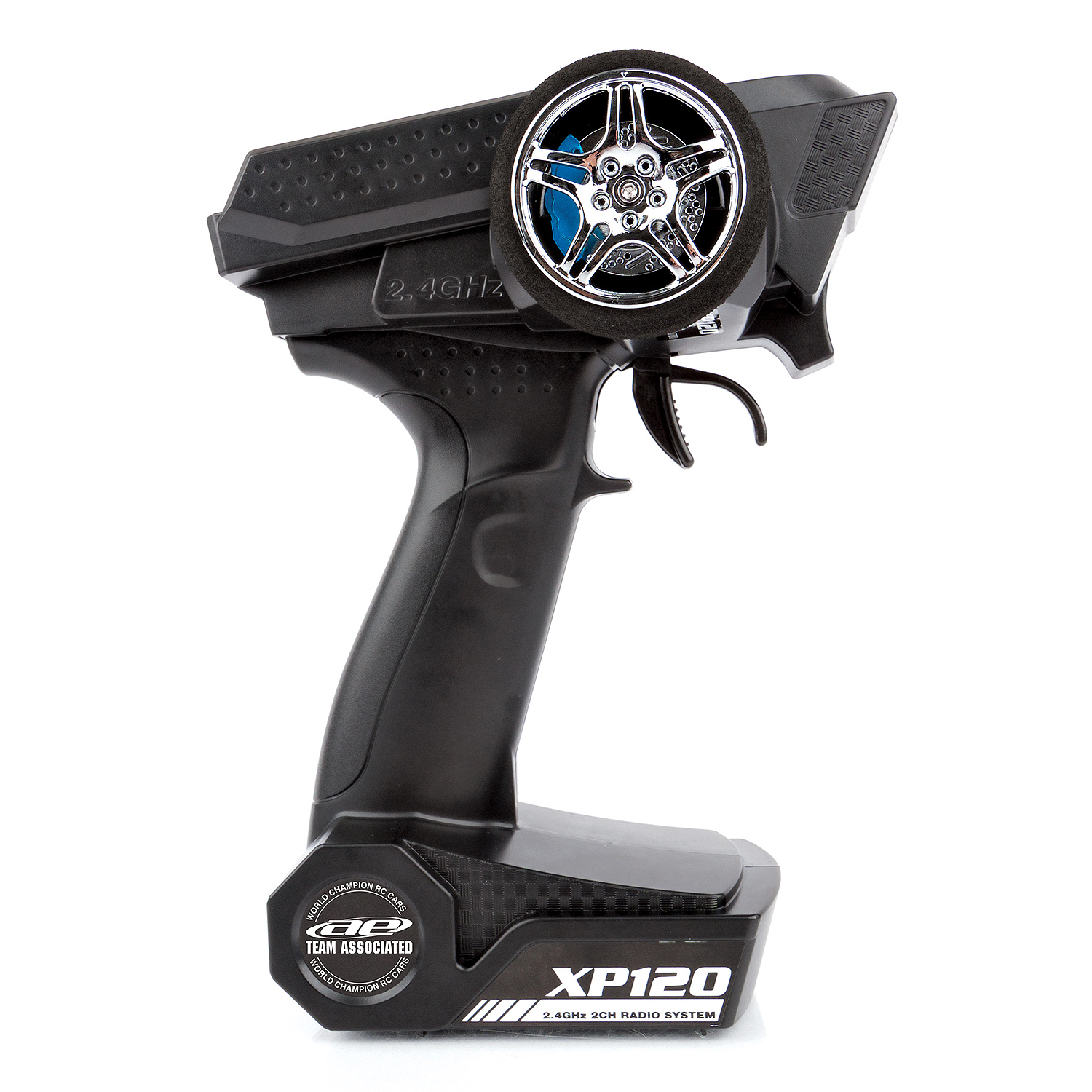
INTRODUCTION
Congratulations on your purchase of Team Associated’s XP120 2-Channel Radio System. Designed using advanced wireless technology, the XP120 will advance and simplify control of your surface model and minimize interference while providing many years of enjoyment. Before installing and operating your new radio system, please take a few minutes to familiarize yourself with the various features of the system by reading this instruction manual thoroughly.
FEATURES
- Steering/Throttle trim adjustment
- Steering/Throttle servo reversing
- Steering/Throttle dual-rate adjustment
- LED on/off indicator
- Low battery warning
- Integrated antenna
- Ergonomic pistol-grip and steering wheel
- Compact lightweight receiver
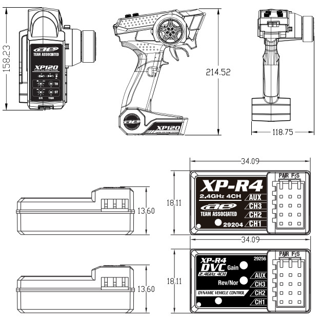
RADIO SPECIFICATIONS
| Model | Team Associated XP120 |
| Part # | 29203 |
| Configuration | Pistol grip |
| Frequency Band | 2.4 GHz |
| Channels | 2 |
| Input voltage | AA x4 |
| Dimensions | 158.23 x 214.52 x 118.75Length x Height x Width (mm) |
RECEIVER SPECIFICATIONS
| Model | XP-R4DVC | XP-R4 |
| Part # | 29256 | 29204 |
| Channes | 4 | |
| Input voltage | 4.8 – 6.0V | |
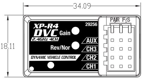
| Dimensions | 34.09 x 13.60 x 18.11 Length x Height x Width (mm) |
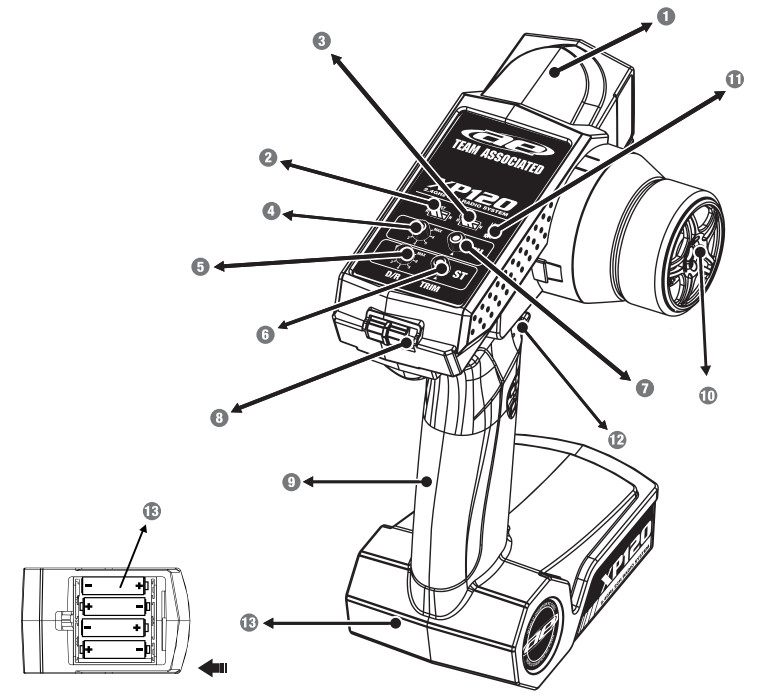
TRANSMITTER CONTROLS/FUNCTIONS
- 4GHx Antenna: The internal antenna is housed within the radio’s plastic housing.
- Steering Reverse Switch: Reverses the steering servo’s direction of rotation.
- Throttle Reverse Switch: Reverses the throttle servo’s direction of rotation.
- Throttle Dual-Rate (TH D/R): Adjust to add or reduce the amount of throttle throw.
- Steering Dual-Rate (ST D/R): Adjust to add or reduce the amount of steering throw.
- Steering Trim: This allows small adjustments to the steering so that your model will travel straight when the steering wheel is in its neutral position.
- Throttle Trim: Allows small adjustments to the throttle to shift the neutral position.
- ON/OFF Switch: Slide to turn the transmitter ON or OFF.
- Pistol Grip Handle: An ergonomic grip allows easy access to the throttle/brake/reverse trigger.
- Steering Wheel: Controls the vehicle’s steering.
- LED Power Indicator: Indicates whether the radio is powered ON or OFF.
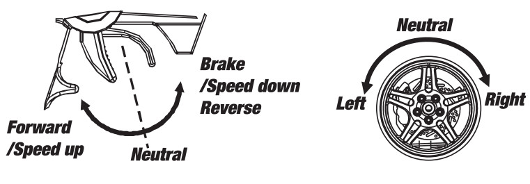
- Throttle/Brake/Reverse Trigger: Pull or push to control the vehicle’s movement forward or backward.
- Battery Box: Slide to remove the cover to remove or install batteries.
INSTALLATION
Mount your receiver in the vehicle’s factory-recommended location using high-quality double-sided tape designed for hobby use while making sure that it is mounted parallel to the ground.Battery Installation and Replacement
- Open the battery box cover to access the batteries.
- Install four (4) alkaline or rechargeable AA-size batteries into the battery box holder.
- Place the battery box cover back into position making sure it is secure.
- Turn the power ON. If the power indicator LED fails to light, check the batteries for insufficient contact or incorrect polarity.
- Replace batteries when the LED Power Indicator flashes.
Checka) Use only new alkaline cells all of the same brand.b) Make certain that the contacts in the battery box holder stay clean by using a pencil eraser to gently remove any corrosion or dirt that may accumulate on them. Clean the tabs each time new batteries are installed.c) If using rechargeable batteries, be sure to follow the battery manufacturer’s charging instructions.
Caution:a) Do not attempt to charge alkaline batteries. They may EXPLODE!b) Always be sure the batteries are installed in the correct polarity order. If the batteries are installed incorrectly, damage to the radio may result.c) Do not continue to operate your radio when the LED Power Indicator begins to flash. Continue only after new batteries are installed.d) When the radio is not in use for more than one week, remove the batteries from the radio.
BINDING THE TRANSMITTER AND REC
- After connecting the receiver to a power source (receiver battery or ESC) and turning it on, connect the Bind connector to the “Pair” pins on the receiver. The LED on the receiver will flash rapidly.
- Switch on the transmitter, and then remove the Bind connector from the receiver.
- The LED on the receiver will now remain solid to indicate successful binding of the transmitter and receiver.
Note: Radio systems installed in RTRs have already been bound. Only when installing a new transmitter or receiver is the above process necessary.
FAILSAFE FUNCTION SETTING
After successful binding of the transmitter and receiver, the fail-safe setting can be saved. If the connection between the transmitter and receiver is interrupted, the vehicle will revert to a preset throttle position.To set this position, place the vehicle on a suitable stand so that the wheels do not touch the ground, then turn the transmitter and vehicle on and install the Bind connector into the “F/S” pins on the receiver. The LED on the receiver will flash rapidly. Now move the throttle trigger to the position that you would like to establish as the fail-safe setting (neutral is recommended) and while maintaining that position, remove the Bind connector from the receiver and immediately plug it back it. The receiver LED should now be solid and the failsafe position set.
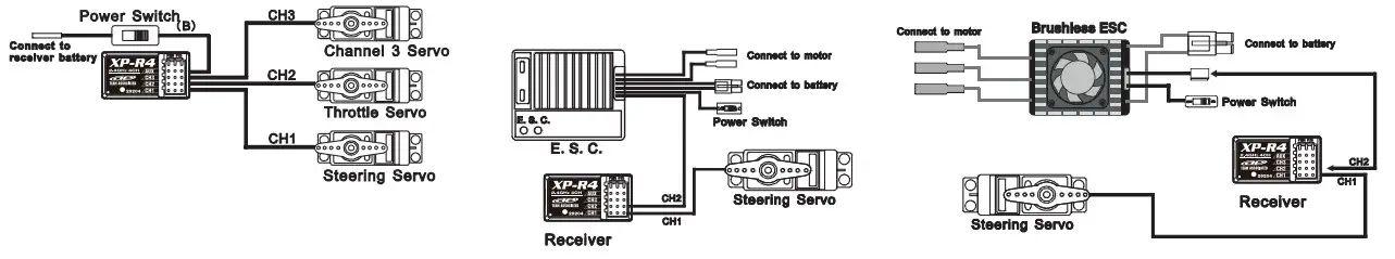
RECEIVER/SERVO/ESC CONNECTIONS
SAFETY PRECAUTIONS
This product is a sophisticated hobby product and not a toy. It must be operated with caution and common sense and requires some basic mechanical ability. Failure to operate this product in a safe and responsible manner could result in injury or damage to the product or property. This product is not intended to be used by children without direct adult supervision. It is essential to read and follow all instructions and warnings found in this manual prior to installation, set up, and use, in order for the product to operate properly and to avoid damage or injury.
OPERATION
Caution:a) Always power ON your transmitter before the ESC and power OFF the ESC before your transmitter.b) Maintain a minimum distance of 40cm (15 3/4″) between the transmitter and vehicle when operating. Note: When using the XP120 in electric-powered vehicles, the throttle trim should always remain in the neutral position. Otherwise, the vehicle may experience the erratic operation of the throttle/brakes/reverse functions.
USING CAUTION WHILE OPERATING
- Do not operate the model or use the radio in the rain, in the presence of lightning, or at night.
- Do not operate the model or use the radio if you have been drinking alcohol or are under the influence of any other substance that will affect your skills.
- Always confirm that the radio has sufficient battery power before operating.
- Keep out of reach of children.
- Do not store the radio in temperatures below -10° C (14° F) or above 40° C (104° F) or in humid, dusty, or in high-vibration environments. Keep the radio away from direct sunlight.
- To prevent corrosion, remove the batteries from the radio if it will be stored for more than one week.
DYNAMIC VEHICLE CONTROL (DVC) SETTINGS
Dynamic Vehicle Control (DVC) automatically counter-steers your vehicle in low traction and/or bumpy conditions which improves handling and reduces lap times. Completely adjustable, DVC can be fine-tuned to suit varying conditions and driver preferences.Gain – This setting adjusts the sensitivity and speed of the DVC counter-steer effect and is adjustable in eight steps indicated by the number of flashes of the LED with 1 being the most sensitive and 7 the least sensitive. Setting 8 disables DVC. A setting of 4 is set by default and is suitable for most applications and conditions. To change the setting, press and release the Gain button. The LED will flash to indicate the new setting. Continue this process until the desired setting is reached making sure to allow the LED sequence to finish before pressing the Gain button again. 34.0Rev/Nor – This setting changes the direction of DVC’s counter-steer effect and is set at Normal by default. In all situations, DVC should counter-steer (steer into the slide) automatically. But in rare cases, the direction setting must be reversed. To reverse the setting, press and hold the Nor/Rev button for 3-4 seconds until the LED flashes twice to indicate that the direction has been changed successfully.
LIMITED WARRANTY
Your radio is warranted to the original purchaser for 120 days (non-EU countries only) from the date of purchase, verified by the sales receipt, against defects in material and workmanship. The product that has been mishandled, abused, used incorrectly, used for an application other than intended, or damaged by the user are not covered under warranty. Associated Electrics Inc. is not liable for any loss or damage, whether direct or indirect, incidental or consequential, or from any special situation, arising from the use, misuse, or abuse of this product.
 Associated cs. Inc. declares that atthis product complies with the ntialrecuirentsEotherelevtpois of the European directive 2014/30/EU.
 The crossed-out wheeled bin means that within the European Union. this product must be taken to a separate waste collection facility at the product’s end of life. Do not dispose of this product as unsorted municipal waste.
 report this ad
![]()
www.TeamAssociated.com26021 Commercentre Dr., Lake Forest, CA 92630 USA
[xyz-ips snippet=”download-snippet”]