
Warning: Use of undefined constant id – assumed ‘id’ (this will throw an Error in a future version of PHP) in /home/admin/domains/manualsplanet.com/public_html/praca/dom_delete_new.php on line 17
Warning: Use of undefined constant id – assumed ‘id’ (this will throw an Error in a future version of PHP) in /home/admin/domains/manualsplanet.com/public_html/praca/dom_delete_new.php on line 18
Warning: Use of undefined constant id – assumed ‘id’ (this will throw an Error in a future version of PHP) in /home/admin/domains/manualsplanet.com/public_html/praca/dom_delete_new.php on line 18
Warning: Creating default object from empty value in /home/admin/domains/manualsplanet.com/public_html/praca/dom_delete_new.php on line 212
Warning: Creating default object from empty value in /home/admin/domains/manualsplanet.com/public_html/praca/dom_delete_new.php on line 138

TUF B360M-PLUSGAMING
E13794First EditionFebruary 2018
Copyright © 2018 ASUSTeK COMPUTER INC. All Rights Reserved.No part of this manual, including the products and software described in it, maybe reproduced, transmitted, transcribed, stored in a retrieval system, or translated into any language in any form or by any means, except documentation kept by the purchaser for backup purposes, without the express written permission of ASUSTeK COMPUTER INC. (“ASUS”).Product warranty or service will not be extended if: (1) the product is repaired, modified, or altered, unless such repair, modification of alteration is authorized in writing by ASUS; or (2) the serial number of the product is defaced or missing.
ASUS PROVIDES THIS MANUAL “AS IS” WITHOUT WARRANTY OF ANY KIND, EITHER EXPRESS OR IMPLIED, INCLUDING BUT NOT LIMITED TO THE IMPLIED WARRANTIES OR CONDITIONS OF MERCHANTABILITY OR FITNESS FOR A PARTICULAR PURPOSE. IN NO EVENT SHALL ASUS, ITS DIRECTORS, OFFICERS, EMPLOYEES, OR AGENTS BE LIABLE FOR ANY INDIRECT, SPECIAL, INCIDENTAL, OR CONSEQUENTIAL DAMAGES (INCLUDING DAMAGES FOR LOSS OF PROFITS, LOSS OF BUSINESS, LOSS OF USE OR DATA, INTERRUPTION OF BUSINESS, AND THE LIKE), EVEN IF ASUS HAS BEEN ADVISED OF THE POSSIBILITY OF SUCH DAMAGES ARISING FROM ANY DEFECT OR ERROR IN THIS MANUAL OR PRODUCT. SPECIFICATIONS AND INFORMATION CONTAINED IN THIS MANUAL ARE FURNISHED FOR INFORMATIONAL USE ONLY, AND ARE SUBJECT TO CHANGE AT ANY TIME WITHOUT NOTICE, AND SHOULD NOT BE CONSTRUED AS A COMMITMENT BY ASUS. ASUS ASSUMES NO RESPONSIBILITY OR LIABILITY FOR ANY ERRORS OR INACCURACIES THAT MAY APPEAR IN THIS MANUAL, INCLUDING THE PRODUCTS AND SOFTWARE DESCRIBED IN IT.Products and corporate names appearing in this manual may or may not be registered trademarks or copyrights of their respective companies, and are used only for identification or explanation and to the owners’ benefit, without intent to infringe.Offer to Provide Source Code of Certain SoftwareThis product contains copyrighted software that is licensed under the General Public License (“GPL”), under the Lesser General Public License Version (“LGPL”), and/or other Free Open Source Software Licenses. Such software in this product is distributed without any warranty to the extent permitted by the applicable law. Copies of these licenses are included in this product. Where the applicable license entitles you to the source code of such software and/or other additional data, you may obtain it for a period of three years after our last shipment of the product, either(1) for free by downloading it from http://support.asus.com/downloador(2) for the cost of reproduction and shipment, which is dependent on the preferred carrier and the location where you want to have it shipped to, by sending a request to:
ASUSTeK Computer Inc.Legal Compliance Dept.15 Li Te Rd.,Beitou, Taipei 112Taiwan
In your request please provide the name, model number, and version, as stated in the About Box of the product for which you wish to obtain the corresponding source code and your contact details so that we can coordinate the terms and cost of shipment with you.The source code will be distributed WITHOUT ANY WARRANTY and licensed under the same license as the corresponding binary/object code.This offer is valid to anyone in receipt of this information.ASUSTeK is eager to duly provide complete source code as required under various Free Open Source Software licenses. If however, you encounter any problems in obtaining the full corresponding source code we would be much obliged if you give us a notification to the email address [email protected], stating the product and describing the problem (please DO NOT send large attachments such as source code archives, etc. to this email address).
Safety information
Electrical safety
- To prevent electrical shock hazards, disconnect the power cable from the electrical outlet before relocating the system.
- When adding or removing devices to or from the system, ensure that the power cables for the devices are unplugged before the signal cables are connected. If possible, disconnect all power cables from the existing system before you add a device.
- Before connecting or removing signal cables from the motherboard, ensure that all power cables are unplugged.
- Seek professional assistance before using an adapter or extension cord. These devices could interrupt the grounding circuit.
- Ensure that your power supply is set to the correct voltage in your area. If you are not sure about the voltage of the electrical outlet you are using, contact your local powercompany.
- If the power supply is broken, do not try to fix it by yourself. Contact a qualified service technician or your retailer.
Operation safety
- Before installing the motherboard and adding components, carefully read all the manuals that came with the package.
- Before using the product, ensure all cables are correctly connected and the power cables are not damaged. If you detect any damage, contact your dealer immediately.
- To avoid short circuits, keep paper clips, screws, and staples away from connectors, slots, sockets, and circuitry.
- Avoid dust, humidity, and temperature extremes. Do not place the product in any area where it may be exposed to moisture.
- Place the product on a stable surface.
- If you encounter technical problems with the product, contact a qualified service technician or your retailer.
About this guide
This user guide contains the information you need when installing and configuring the motherboard.How this guide is organizedThis guide contains the following parts:
- Chapter 1: Product introductionThis chapter describes the features of the motherboard and the new technology it supports. It includes descriptions of the switches, jumpers, and connectors on the motherboard.
- Chapter 2: BIOS informationThis chapter discusses changing system settings through the BIOS Setup menus.
Where to find more informationRefer to the following sources for additional information and for product and software updates.
1. ASUS websitesThe ASUS website provides updated information on ASUS hardware and software products. Refer to the ASUS contact information.2. Optional documentationYour product package may include optional documentation, such as warranty flyers, that may have been added by your dealer. These documents are not part of the standard package.
Conventions Used in this guide
To ensure that you perform certain tasks properly, take note of the following symbols used throughout this manual.
 DANGER/WARNING: Information to prevent injury to yourself when completing a task.
 CAUTION: Information to prevent damage to the components when completing a task
 IMPORTANT: Instructions that you MUST follow to complete a task.
 NOTE: Tips and additional information to help you complete a task.
Typography
| Bold text | Indicates a menu or an item to select. |
| Italics | Used to emphasize a word or a phrase. |
| <Key> | Keys enclosed in the less-than and greater-than signmeans that you must press the enclosed key.Example: <Enter> means that you must press the Enter orReturn key. |
| <Key1> + <Key2> + <Key3> | If you must press two or more keys simultaneously, the keynames are linked with a plus sign (+). |
Package contents
Check your motherboard package for the following items.
| Motherboard | ASUS TUF B360M-PLUS GAMING motherboard |
| Cables | 2 x Serial ATA 6.0 Gb/s cables |
| Accessories | 1 x I/O Shield1 x M.2 Screw package1 x TUF GAMING sticker |
| Application DVD | Support DVD |
| Documentation | User GuideTUF Certification Card |
If any of the above items are damaged or missing, contact your retailer.
TUF B360M-PLUS GAMING specifications summary
| CPU | LGA1151 socket for 8th Generation Intel ® Core™ i7/i5/i3, Pentium® and Celeron® processors Supports Intel® 14nm CPUSupports Intel® Turbo Boost Technology 2.0** The Intel® Turbo Boost Technology 2.0 support depends on the CPU types.** Refer to www.asus.com for Intel® CPU support list. |
| Chipset | Intel® B360 Chipset |
| Memory | 4 x DIMMs, maximum 64GB, DDR4 2600/2400/2133 MHz, non-ECC, un-buffered memoryDual-channel memory architectureSupports Intel® Extreme Memory Profile (XMP)* The maximum memory frequency supported varies by processor.** DDR4 2666MHz and higher memory modules will run at max. 2666MHz on Intel® 8thGen. 6-core or higher processors.*** Refer to www.asus.com for the latest Memory QVL (Qualified Vendors List). |
| Expansion slots | 1 x PCI Express 3.0/2.0 x16 slot (at x16 mode)2 x PCI Express 3.0/2.0 x1 slots |
| Graphics | Integrated graphics processor – Intel®HD Graphics supportMulti-VGA output support: HDMI/DVI-D ports– Supports HDMI 1.4b with max. resolution 4096 x / 2560 x – Supports DVI-D with a maximum resolution of 1920 x 1200 @ 60Hz Supports Intel®InTru™ 3D/Quick Sync Video/Clear Video HD Technology/Insider™Maximum shared memory of 1024 MB (for iGPU exclusively) |
| Storage | Intel® B360 Chipset:– 1 x M.2_1 Socket 3 with M Key, type 2242/2260/2280 storage devices support(both SATA and PCIe 3.0 x 4 mode)*– 1 x M.2_2 Socket 3 with M Key, type 2242/2260/2280 storage devices support (PCIe 3.0 x 4 mode)– 6 x SATA 6.0 Gb/s ports (gray)– Intel® Optane™ Memory Ready*** When a device in SATA mode is installed on the M.2_1 socket, SATA_2 port cannot be used.** Only the M.2_2 socket can support Intel® Optane TM memory. |
| LAN | Intel ® I219-V Gigabit LAN – Dual interconnection between the integrated Media Access Controller (MAC) and physical layer (PHY)TUF LANGuard |
| Audio | Realtek ® ALC887 8-channel High Definition Audio CODEC– Audio Shielding: Ensures precision analog/digital separation and greatly reduced multi-lateral interference– Dedicated audio PCB layers: Separate layers for left and right channels to guard the quality of the sensitive audio signals– Premium Japanese audio capacitors: Provide warm, natural, and immersive sound with exceptional clarity and fidelity– Supports Jack-Detection and Front Panel Jack-Retasking |
| USB | Intel ® B360 Chipset– 2 x USB 3.1 Gen 2 (up to 10Gbps) ports (2 ports @back panel, teal blue, Type A)– 3 x USB 3.1 Gen 1 (up to 5Gbps) ports (2 ports @mid-board, 1 port @back panel, Type C)– 6 x USB 2.0/1.1 ports (4 ports @mid-board, 2 ports @back panel, black, Type A) |
| ASUS special features | TUF Components (TUF Cap, TUF Chokes, MOSFET & LANGuard; certified by military-standard)ASUS TUF PROTECTION– ASUS SafeSlot – Protect your graphics card investment– ASUS ESD Guard: Enhanced ESD protection– ASUS Overvoltage Protection: World-class circuit-protecting power design– ASUS Stainless-Steel Back I/O: 3X corrosion-resistance for greater durability!– ASUS DIGI+ VRM: 5 Phase digital power design Superb Performance ASUS OptiMem– Improved DDR4 stability M.2 onboard– The latest transfer technologies with up to 32Gb/s data transfer speeds ASUS Fan Xpert 2+– Ultimate cooling and quietness ASUS EPU – EPU UEFI BIOS– Most advanced options with fast response time |
| ASUS specialfeatures | Gaming ScenarioAura– Bright up your BuildAudio Features– Audio that roars on the battlefieldASUS Exclusive Features– ASUS Ai Charger– ASUS AI Suite 3– ASUS File Transfer– ASUS PC CleanerEZ DIYUEFI BIOS EZ Mode– Featuring friendly graphics user interface– ASUS CrashFree BIOS 3– ASUS EZ Flash 3Q-Design– ASUS Q-DIMM– ASUS Q-Slot |
| ASUS Quiet Thermal Solution | Quiet Thermal Design– ASUS Fan Xpert 2+– Stylish Fanless Design: PCH Heat-sink & MOS Heat-sink |
| Rear panel I/O ports | 1 x PS/2 keyboard/mouse combo port1 x HDMI port1 x DVI-D port2 x USB 3.1 Gen 2 (up to 10Gbps) ports (Type A, teal blue)1 x USB 3.1 Gen 1 (up to 5Gbps) port (Type C)2 x USB 2.0/1.1 ports1 x LAN (RJ-45) port3 Audio jacks support 8 channel** Use a chassis with HD audio module in the front panel to support an 8-channel audio output. |
| Internal connectors | 1 x USB 3.1 Gen 1 (up to 5Gbps) connector support additional 2 USB ports (19-pin)2 x USB 2.0/1.1 connectors support additional 4 USB ports6 x SATA 6.0Gb/s connectors (gray)2 x M.2 Socket 3 (for M Key, type 2242/2260/2280 devices)1 x CPU Fan connector2 x Chassis Fan Connectors (4-pin) for both 3-pin(DC mode) and 4-pin (PWM mode) coolers control1 x Front panel audio connector (AAFP)1 x System panel connector1 x Clear CMOS header1 x S/PDIF out header |
| Internal connectors | 1 x 24-pin EATX Power connector1 x 8-pin EATX 12V Power connector1 x COM header1 x Aura RGB Strip header |
| BIOS | 128Mb Flash ROM, UEFI AMI BIOS, PnP, SM BIOS 3.1, ACPI 6.1, Multilanguage BIOS, ASUS EZ Flash 3, CrashFree BIOS 3, F3 My Favorites, Last Modified log, F4 AURA ON/OFF, F6 Qfan Control, F9 Search, F12 PrintScreen, and ASUS DRAM SPD (Serial Presence Detect) memory information |
| Manageability | WOL by PME, PXE |
| Support DVD | DriversASUS UtilitiesASUS EZ UpdateAnti-virus software (OEM version) |
| OS Support | Windows® 10 (64-bit) |
| Form Factor | mATX Form Factor, 9.6”x 9.1” (24.4cm x 23.1cm) |
Specifications are subject to change without notice.
Product introduction
Motherboard overview
- Unplug the power cord from the wall socket before touching any component.
- Before handling components, use a grounded wrist strap or touch a safely grounded object or a metal object, such as the power supply case, to avoid damaging them due to static electricity.
- Before you install or remove any component, ensure that the ATX power supply is switched off or the power cord is detached from the power supply. Failure to do so may cause severe damage to the motherboard, peripherals, or components.
- Unplug the power cord before installing or removing the motherboard. Failure to do so can cause you physical injury and damage to motherboard components.
 Scan the QR code to get the detailed pin definitions.
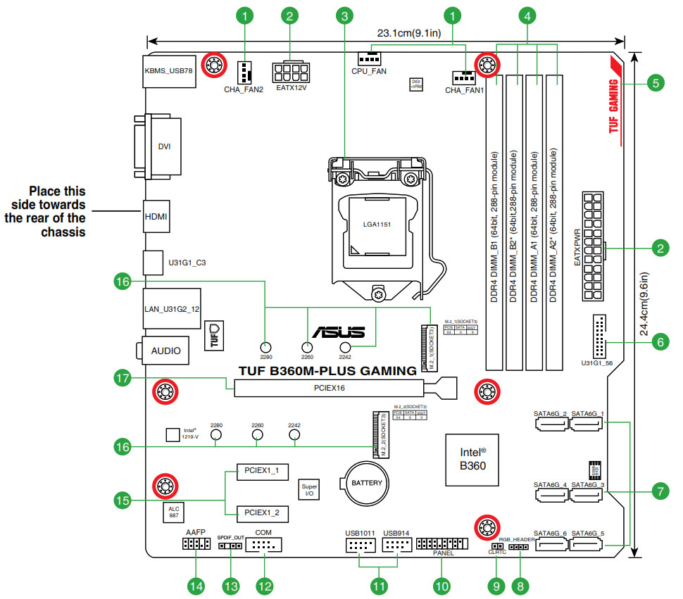

- CPU and chassis fan connectors (4-pin CPU_FAN, 4-pin CHA_FAN1~2)Connect the fan cables to the fan connectors on the motherboard, ensuring that the black wire of each cable matches the ground pin of the connector. Do not forget to connect the fan cables to the fan connectors. Insufficient airflow inside the system may damage the motherboard components.These are not jumpers! Do not place jumper caps on the fan connectors! The CPU_FAN connector supports a CPU fan of maximum 1A (12 W) fan power.
- ATX power connectors (24-pin EATXPWR, 8-pin EATX12V)Correctly orient the ATX power supply plugs into these connectors and push down firmly until the connectors completely fit.
- For a fully configured system, we recommend that you use a power supply unit (PSU) that complies with ATX 12 V Specification 2.0 (or later version) and provides a minimum power of 350 W. This PSU type has 24-pin and 8-pin power plugs.
- We recommend that you use a PSU with higher power output when configuring a system with more power-consuming devices or when you intend to install additional devices. The system may become unstable or may not boot up if the power is inadequate.
- If you are uncertain about the minimum power supply requirement for your system, refer to the Recommended Power Supply Wattage Calculator at http://support. asus.com.cn/PowerSupply.aspx?SLanguage=en for details.
3. Intel ® LGA1151 CPU socketInstall Intel ® LGA1151 CPU into this surface mount LGA1151 socket, which is designed for 8th Generation Intel ® Core™ i7 / i5 / i3, Pentium ® and Celeron processors.
For more details, refer to Central Processing Unit (CPU).
4. DDR4 DIMM slotsInstall 2 GB, 4 GB, 8 GB, and 16 GB unbuffered non-ECC DDR4 DIMMs into these DIMM sockets.
For more details, refer to System memory.
5. RGB LEDThe RGB LED lighting control provides several lighting schemes, which allow you to customize your favorite LED effect. You can set your favorite LED effect to cast a stunning multi-color glow across your build, change shades to indicate CPU temperature, pulsate in time to the beat of your music or set your favorite color for each pair of LEDs
6. USB 3.1 Gen1 (Up to 5Gbps) connectors (20-1 pin U31G1_56)This connector allows you to connect a USB 3.1 Gen 1 module for additional USB 3.1 Gen 1 front or rear panel ports. With an installed USB 3.1 Gen 1 module, you can enjoy all the benefits of USB 3.1 Gen 1 including faster data transfer speeds of up to 5 Gb/s, faster charging time for USB-chargeable devices, optimized power efficiency, and backward compatibility with USB 2.0.
7. Intel ® B360 Serial ATA 6.0Gb/s connectors (7-pin SATA6G_1~6)These connectors connect to Serial ATA 6.0 Gb/s hard disk drives via Serial ATA 6.0 Gb/s signal cables.
8. RGB header (4-pin RGB_HEADER)This header is for RGB LED strips.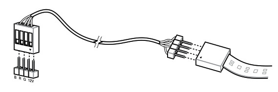 The RGB header supports 5050 RGB multi-color LED strips (12V/G/R/B), with a maximum power rating of 3A (12V), and no longer than 3 m. Before you install or remove any component, ensure that the ATX power supply is switched off or the power cord is detached from the power supply. Failure to do so may cause severe damage to the motherboard, peripherals, or components.
- Actual lighting and color will vary with LED strips.
- If your LED strip does not light up, check if the RGB LED extension cable and the RGB LED strip is connected in the correct orientation, and the 12V connector is aligned with the 12V header on the motherboard.
- The LED strip will only light up when the system is operating.
- The LED strips are purchased separately.
9. Clear RTC RAM (2-pin CLRTC)This header allows you to clear the CMOS RTC RAM data of the system setup information such as date, time, and system passwords.![]() To erase the RTC RAM:1. Turn OFF the computer and unplug the power cord.2. Use a metal object such as a screwdriver to short the two pins.3. Plug the power cord and turn ON the computer.4. Hold down the <Del> key during the boot process and enter BIOS setup to re-enter data.
To erase the RTC RAM:1. Turn OFF the computer and unplug the power cord.2. Use a metal object such as a screwdriver to short the two pins.3. Plug the power cord and turn ON the computer.4. Hold down the <Del> key during the boot process and enter BIOS setup to re-enter data.
If the steps above do not help, remove the onboard battery and short the two pins again to clear the CMOS RTC RAM data. After clearing the CMOS, reinstall the battery.
10. System panel connector (20-5 pin PANEL)This connector supports several chassis-mounted functions.
11. USB 2.0 connectors (10-1 pin USB1011, USB914)Connect a USB module cable to any of these connectors, then install the module to a slot opening at the back of the system chassis. These USB connectors comply with USB 2.0 specifications and support up to 480Mbps connection speed.
12. Serial port connector (10-1 pin COM)Connect the serial port module cable to this connector, then install the module to a slot opening at the back of the system chassis.
13. Digital audio connector (4-1 pin SPDIF_OUT)Connect the S/PDIF Out module cable to this connector, then install the module to a slot opening at the back of the system chassis.
14. Front panel audio connector (10-1 pin AAFP)This connector is for a chassis-mounted front panel audio I/O module that supports either HD Audio or legacy AC`97 audio standard. Connect one end of the front panel audio I/O module cable to this connector.• We recommend that you connect a high-definition front panel audio module to this connector to avail of the motherboard’s high-definition audio capability.• If you want to connect a high-definition front panel audio module to this connector, set the Front Panel Type item in the BIOS setup to [HD Audio].If you want to connect an AC’97 front panel audio module to this connector, set the item to [AC97]. By default, this connector is set to [HD Audio].
15. PCI Express 3.0/2.0 x1 slotsThis motherboard has two PCI Express 3.0/2.0 x1 slots that support PCI Express x1 network cards, SCSI cards, and other cards that comply with the PCI Express specifications.
16. M.2 socket 3These sockets allow you to install M.2 (NGFF) SSD modules.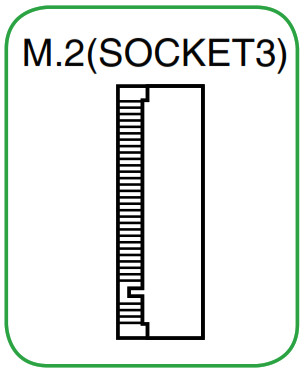 The M.2 (NGFF) SSD module is purchased separately.
- These M.2 sockets support M Key and 2242/2260/2280 storage devices.
- Both M.2 sockets can support data transfer speed up to 32Gb/s.
- Only the M.2_2 socket can support Intel® OptaneTM memory.
- Only the M.2_1 socket can support SATA mode storage devices. When a device inSATA mode is installed on the M.2_1 socket, SATA_2 is disabled.
17. PCI Express 3.0/2.0 x16 slotThis motherboard supports one PCI Express 3.0/2.0 x16 graphic card that complies with the PCI Express specifications.
Rear panel connectors
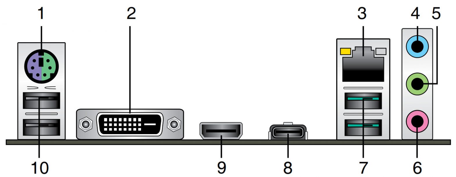
1. PS/2 Mouse/Keyboard combo port. This port connects to a PS/2 mouse or PS/2 keyboard.2. DVI-D port. This port is for any DVI-D compatible device.
DVI-D can not be converted to output from RGB Signal to CRT and is not compatible with DVI-I.
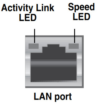
3. LAN (RJ-45) port. This port allows Gigabit connection to a Local Area Network (LAN) through a network hub.
LAN port LED indications
| Activity/Link LED | Speed LED | ||
| Status | Description | Status | Description |
| Off | No link | OFF | 10Mbps connection |
| Orange | Linked | ORANGE | 100Mbps connection |
| Orange (Blinking) | Data activity | GREEN | 1Gbps connection |
| Orange (Blinkingthen steady) | Ready to wakeup from S5 mode |
4. Line In port (light blue). This port connects to the tape, CD, DVD player, or other audio sources.5. Line Out port (lime). This port connects to a headphone or a speaker. In the 4.1, 5.1, and 7.1-channel configurations, the function of this port becomes Front Speaker Out.6. Microphone port (pink). This port connects to a microphone.
Refer to the audio configuration table for the function of the audio ports in 2.1, 4.1, 5.1, or 7.1-channel configuration.\
Audio 2.1, 4.1, 5.1, or 7.1-channel configuration
| Port | Headset2.1-channel | 4.1-channel | 5.1-channel | 7.1-channel |
| Light Blue (Rear panel) | Line In | Rear Speaker Out | Rear Speaker Out | Rear Speaker Out |
| Lime (Rear panel) | Line Out | Front Speaker Out | Front Speaker Out | Front Speaker Out |
| Pink (Rear panel) | Mic In | Mic In | Bass/Center | Bass/Center |
| Lime (Front panel) | Side Speaker Out |
To configure a 7.1-channel audio output:Use a chassis with HD audio module in the front panel to support a 7.1-channel audio output.
7. USB 3.1 Gen 2 (up to 10Gbps) ports (teal blue, Type A). These 9-pin Universal Serial Bus 3.1 (USB 3.1) Gen 2 ports are for USB 3.1 Gen 2 devices.
• USB 3.1 Gen 2 / Gen 1 devices can only be used for data storage.• Due to the design of the Intel® 300 series chipset, all USB devices connected to theUSB 2.0 and USB 3.1 Gen 2 / Gen 1 ports are controlled by the xHCI controller. Some legacy USB devices must update their firmware for better compatibility.• We strongly recommend that you connect USB 3.1 Gen 2 devices to USB 3.1 Gen 2 ports for faster and better performance from your USB 3.1 Gen 2 devices.
8. USB 5Gb/s Type C port. This 24-pin Universal Serial Bus (USB) port is for USB (Type C) devices.9. HDMI port. This port is for a High-Definition Multimedia Interface (HDMI) connector and is HDCP compliant allowing playback of HD DVD, Blu-ray, and other protected content.10. USB 2.0 ports. These 4-pin Universal Serial Bus (USB) ports are for USB 2.0/1.1 devices.
Central Processing Unit (CPU)This motherboard comes with a surface mount LGA1151 socket designed for the 8th Generation Intel ® Core™ i7 / Core™ i5 / Core™ i3, Pentium ® and Celeron ® processors.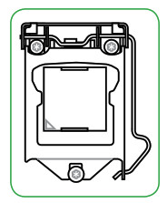 Unplug all power cables before installing the CPU.
- Ensure that you install the correct CPU designed for the LGA1151 socket only. DO NOT install a CPU designed for LGA1150, LGA1155 and LGA1156 sockets on theLGA1151 socket.
- Upon purchase of the motherboard, ensure that the PnP cap is on the socket and the socket contacts are not bent. Contact your retailer immediately if the PnP cap is missing, or if you see any damage to the PnP cap/socket contacts/motherboard components.
- Keep the cap after installing the motherboard. ASUS will process Return Merchandise Authorization (RMA) requests only if the motherboard comes with the cap on the LGA1151 socket.
- The product warranty does not cover damage to the socket contacts resulting from incorrect CPU installation/removal, or misplacement/loss/incorrect removal of the PnP cap.
Installing the CPU
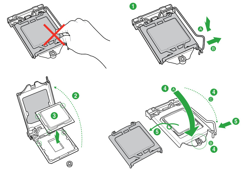
Apply the Thermal Interface Material to the CPU heatsink and CPU before you install the heatsink and fan if necessary.
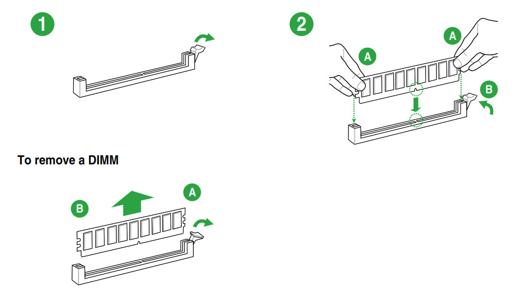
System memory
Overview
This motherboard comes with four Double Data Rate 4 (DDR4) Dual Inline Memory Module (DIMM) sockets. A DDR4 module is notched differently from a DDR, DDR2, or DDR3 module. DO NOT install a DDR, DDR2, or DDR3 memory module to the DDR4 slot.

- You may install varying memory sizes in Channel A and Channel B. The system maps the total size of the lower-sized channel for the dual-channel configuration. Any excess memory from the higher-sized channel is then mapped for single-channel operation.
- Always install DIMMs with the same CAS latency. For optimal compatibility, we recommend that you install memory modules of the same version or date code (D/C) from the same vendor. Check with the retailer to get the correct memory modules.
- DDR4 2666MHz and higher memory modules will run at max. 2666MHz on Intel® 8th Generation 6-core or higher processors.
- Memory modules with memory frequency higher than 2133/2400/2666 MHz and its corresponding timing or the loaded X.M.P. Profile is not the JEDEC memory standard. The stability and compatibility of these memory modules depend on the CPU’s capabilities and other installed devices.
- The default memory operation frequency is dependent on its Serial Presence Detect (SPD), which is the standard way of accessing information from a memory module. Under the default state, some memory modules for overclocking may operate at a lower frequency than the vendor-marked value.
- For system stability, use a more efficient memory cooling system to support a full memory load (4 DIMMs).
- Refer to www.asus.com for the latest Memory QVL (Qualified Vendors List)
Recommended memory configurations
Installing a DIMM
BIOS information
- Scan the QR code to view the BIOS update guide.
- Before using the ASUS CrashFree BIOS 3 utility, rename the BIOS file in the removable device into TB360MP.CAP.

BIOS setup program
Use the BIOS Setup program to update the BIOS or configure its parameters. The BIOS screens include navigation keys and brief online help to guide you in using the BIOS Setup program.Entering BIOS Setup at startupTo enter BIOS Setup at startup:Press <Delete> or <F2> during the Power-On Self Test (POST). If you do not press <Delete> or <F2>, POST continues with its routines.Entering BIOS Setup after POSTTo enter BIOS Setup after POST:Press <Ctrl>+<Alt>+<Del> simultaneously.Press the reset button on the system chassis.Press the power button to turn the system off then back on. Do this option only if you failed to enter BIOS Setup using the first two options.
Using the power button, reset button, or the <Ctrl>+<Alt>+<Del> keys to force reset from a running operating system can cause damage to your data or system. We recommend you always shut down the system properly from the operating system.
- The BIOS setup screens shown in this section are for reference purposes only, and may not exactly match what you see on your screen.
- Visit the ASUS website at www.asus.com to download the latest BIOS file for this motherboard.
- If the system becomes unstable after changing any BIOS setting, load the default settings to ensure system compatibility and stability. Select the Load OptimizedDefaults item under the Exit menu or press hotkey F5.
- If the system fails to boot after changing any BIOS setting, try to clear the CMOS and reset the motherboard to the default value. See section Motherboard overview for information on how to erase the RTC RAM.
BIOS menu screenThe BIOS setup program can be used under two modes: EZ Mode and Advanced Mode. Press <F7> to change between the two modes.
EZ Mode
By default, the EZ Mode screen appears when you enter the BIOS setup program. The EZ Mode provides you an overview of the basic system information and allows you to select the display language, system performance mode, fan profile, and boot device priority. To access the Advanced Mode, click Advanced Mode(F7) or press <F7>.
The default screen for entering the BIOS setup program can be changed. Refer to the Setup Mode item under the Boot menu for details. The boot device options vary depending on the devices you installed to the system.
Advanced Mode
The Advanced Mode provides advanced options for experienced end-users to configure the BIOS settings. The figure below shows an example of the Advanced Mode. Refer to the following sections for the detailed configurations.
To access the EZ Mode, click EzMode(F7) or press <F7>.
Search on FAQ
Move your mouse over this button to show a QR code. Scan this QR code with your mobile device to connect to the ASUS BIOS FAQ web page. You can also scan the QR code below.

The Exit menu items allow you to load the optimal default values for the BIOS items and save or discard your changes to the BIOS items.
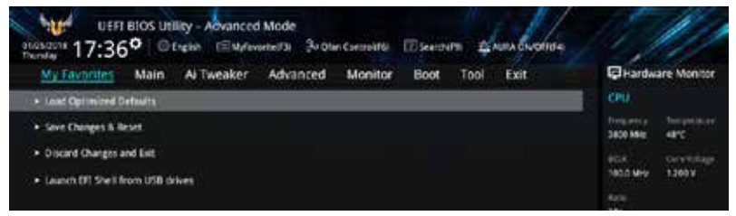
Load Optimized DefaultsThis option allows you to load the default values for each of the parameters on the Setup menus. When you select this option or if you press <F5>, a confirmation window appears. Select OK to load the default values.
Save Changes & ResetOnce you are finished making your selections, choose this option from the Exit menu to ensure the values you selected are saved. When you select this option or if you press <F10>, a confirmation window appears. Select OK to save changes and exit.
Discard Changes and ExitThis option allows you to exit the Setup program without saving your changes. When you select this option or if you press <Esc>, a confirmation window appears. Select OK to discard changes and exit.
Launch EFI Shell from USB drivesThis option allows you to attempt to launch the EFI Shell application (shellx64.efi) from one of the available USB devices.
Appendix
NoticesFederal Communications Commission Statement
This device complies with Part 15 of the FCC Rules. Operation is subject to the following two conditions:
- This device may not cause harmful interference.
- This device must accept any interference received including interference that may cause undesired operation.This equipment has been tested and found to comply with the limits for a Class B digital device, pursuant to Part 15 of the FCC Rules. These limits are designed to provide reasonable protection against harmful interference in a residential installation. This equipment generates, uses, and can radiate radio frequency energy and, if not installed and used in accordance with the manufacturer’s instructions, may cause harmful interference to radio communications. However, there is no guarantee that interference will not occur in a particular installation. If this equipment does cause harmful interference to radio or television reception, which can be determined by turning the equipment off and on, the user is encouraged to try to correct the interference by one or more of the following measures:
- Reorient or relocate the receiving antenna.
- Increase the separation between the equipment and receiver.
- Connect the equipment to an outlet on a circuit different from that to which the receiver is connected.
- Consult the dealer or an experienced radio/TV technician for help.
The use of shielded cables for the connection of the monitor to the graphics card is required to assure compliance with FCC regulations. Changes or modifications to this unit not expressly approved by the party responsible for compliance could void the user’s authority to operate this equipment.
Compliance Statement of Innovation, Science, and Economic Development Canada (ISED)This device complies with Innovation, Science, and Economic Development Canada license-exempt RSS standard(s). Operation is subject to the following two conditions: (1) this device may not cause interference, and (2) this device must accept any interference, including interference that may cause undesired operation of the device.CAN ICES-3(B)/NMB-3(B)
REACH
Complying with the REACH (Registration, Evaluation, Authorisation, and Restriction of Chemicals) regulatory framework, we published the chemical substances in our products on the ASUS REACH website at http://csr.asus.com/english/REACH.htm.
 DO NOT throw the motherboard in municipal waste. This product has been designed to enable proper reuse of parts and recycling. This symbol of the crossed-out wheeled bin indicates that the product (electrical and electronic equipment) should not be placed in municipal waste. Check local regulations for disposal of electronic products.
 DO NOT throw the mercury-containing button cell battery in municipal waste. This symbol of the crossed-out wheeled bin indicates that the battery should not be placed in municipal waste.
ASUS Recycling/Takeback ServicesASUS recycling and takeback programs come from our commitment to the highest standards for protecting our environment. We believe in providing solutions for you to be able to responsibly recycle our products, batteries, other components as well as packaging materials. Please go to http://csr.asus.com/english/Takeback.htm for detailed recycling information in different regions.
Regional notice for California
 WARNING
Cancer and Reproductive Harm – www.P65Warnings.ca.gov
Google™ License TermsCopyright© 2018 Google Inc. All Rights Reserved.Licensed under the Apache License, Version 2.0 (the “License”); you may not use this file except in compliance with the License. You may obtain a copy of the License at: http://www.apache.org/licenses/LICENSE-2.0 Unless required by applicable law or agreed to in writing, software distributed under the License is distributed on an “AS IS” BASIS, WITHOUT WARRANTIES OR CONDITIONS OF ANY KIND, either express or implied.See the License for the specific language governing permissions and limitations under the License.
ASUSTeK Computer Inc. hereby declares that this device is in compliance with the essential requirements and other relevant provisions of related Directives. Full text of EU declaration of conformity is available at: www.asus.com/support
ASUS contact information
ASUSTeK COMPUTER INC.
Address : 4F, No. 150, Li-Te Road, Peitou, Taipei 112, TaiwanTelephone : +886-2-2894-3447Fax : +886-2-2890-7798Web site : www.asus.com
Technical SupportTelephone : +86-21-38429911Fax : +86-21-5866-8722, ext. 9101#Online support: http://qr.asus.com/techservASUS COMPUTER INTERNATIONAL (America)Address : 800 Corporate Way, Fremont, CA 94539, USATelephone : +1-510-739-3777Fax : +1-510-608-4555Web site: http://www.asus.com/us/Technical Support Support fax : +1-812-284-0883Telephone : +1-812-282-2787Online support: http://qr.asus.com/techservASUS COMPUTER GmbH (Germany and Austria)Address: Harcourt Str. 21-23, 40880 Ratingen, GermanyFax : +49-2102-959931Web site: http://www.asus.com/deOnline contact: http://eu-rma.asus.com/salesTechnical SupportTelephone : +49-2102-5789555Support Fax : +49-2102-959911Online support: http://qr.asus.com/techserv
FCC COMPLIANCE INFORMATIONPer FCC Part 2 Section 2.1077

Responsible Party: Asus Computer InternationalAddress: 800 Corporate Way, Fremont, CA 94539.Phone/Fax No: (510)739-3777/(510)608-4555
hereby declares that the productProduct Name: MotherboardModel Number: TUF B360M-PLUS GAMINGcompliance statement:
This device complies with part 15 of the FCC Rules. Operation is subject to the following two conditions: (1) This device may not cause harmful interference, and (2) this device must accept any interference received, including interference that may cause undesired oper
References
[xyz-ips snippet=”download-snippet”]