ATLONA AT-HDVS-CAM-HDBT-BK PTZ Camera with HDBaseT Output
PTZ Camera with HDBaseT Output
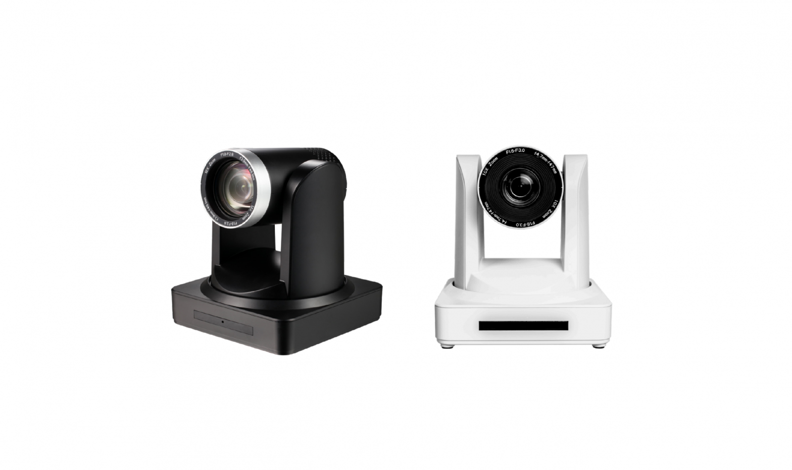
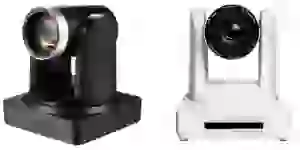
The Atlona AT-HDVS-CAM-HDBT is an enterprise-grade PTZ camera designed for use in video conferencing and other applications such as lecture capture and distance learning. It features an HDBaseT output for extending video, power, and camera control over distances up to 330 feet (100 meters). The HDVS-CAM-HDBT is ideal for remotely interfacing into HDBaseT equipped switchers and extenders, for use with a video conferencing codec, lecture capture appliance, or PC equipped for video capture. Camera control over HDBaseT or TCP/IP facilitates remote integration into AV control systems. The HDVS-CAM HDBT delivers high performance, professional-quality imaging with video resolutions up to 1080p @ 60 Hz, as well as fast and accurate auto-focusing, and a fast yet quiet pan and tilt mechanism. Also available is H.264 or H.265 streaming over IP with support for RTMP and RTSP protocols. This PTZ camera is ideal for large meeting spaces, classrooms, training rooms, and many other environments. The HDVSCAM-HDBT is available in black or white.
Package Contents
1 x AT-HDVS-CAM-HDBT-BK or AT-HDVS-CAM-HDBT-WH1 x Wall mounting plate1 x 1/4 20OUNC screws1 x IR Remote Control1 x USB A cable1 x VISCA to RS-232 DB-9 adapter2 x AAA battery1 x Installation Guide
Panel Descriptions
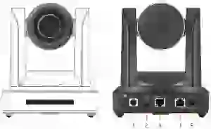
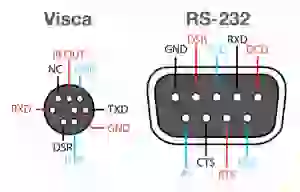
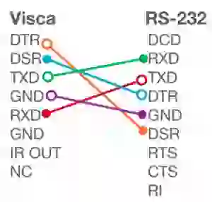
- RS-232Connect included VISCA to RS-232 adapter here to control the camera with a third party software or hardware controller.
- AUDIO INPort not used.
- HDBaseT OUTConnect to a compatible PoE switcher or receiver, such as: AT-OME-RX11, ATOME-PS62, etc
- LANConnect to a network switch to control the unit via TCP/IP or webGUI.
- DC 12VConnect the included 12V power supply to this port.
Mounting Instructions
The HDVS-CAM-HDBT has two installation options, wall mount (included) and ceiling mount (purchased separately).
Wall Mount installationTo install the HDVS-CAM-HDBT, 4 M6 swelling bolts, 1 1/4 20UNC bolt, 4 M6 nuts & shims, the included wall mount bracket, and the HDVS-CAM-HDBT are needed.
- Install the M6 swelling bolts in a rectangular pattern on the wall, 100 mm wide and 50 mm high.
- Attached the wall mount bracket onto the wall, by placing them on the M6 swelling bolts and securing it with the M6 nuts and shims.
- Once the wall mount bracket is secure on the wall, place the camera on the top of the wall mount bracket and secure it with the 1/4 20UNC bolt.

Ceiling Mount installationTo install the HDVS-CAM-HDBT, 4 PA3X30 self-tapping screws, 4 PM3X6 screws, 4 screw stoppers, 1 1/4 20UNC screw, the optional ceiling upper and lower covering plates, and the HDVS-CAM-HDBT are needed.
- Install the 4 screw stoppers in the ceiling.
- Connect the upper ceiling covering plate to the screw stoppers using the PA3X30 self tapping screws.
- Connect the lower ceiling covering plate to the bottom of the HDVS-CAM-HDBT using the 1/4 20UNC screw.
- Mount the lower ceiling covering plate to the upper ceiling plate using 3 PM3X6 bolts.


![]() NOTE: The camera picture will need to be inverted for video to be viewed correctly. View the HDVS-CAM-HDBT manual for instructions on how to invert video.
NOTE: The camera picture will need to be inverted for video to be viewed correctly. View the HDVS-CAM-HDBT manual for instructions on how to invert video.
Installation
- *Optional* Connect the Ethernet cable to the LAN port on the back of the HDVS-CAM.
- Connect a compatible PoE HDBaseT switcher or receiver (e.g. AT-OME-RX11, AT-OMEPS62, etc) to this port.
- *Optional* Connect the Visca to RS-232 cable to the Visca port for RS-232 control.
- *Optional* If a PoE device is unavailable, connect the DC 12V power cable to the unit.
Cable Recommendation GuidelinesRefer to the tables below for recommended cabling when using Altona products with HDBaseT.The green bars indicate the signal quality when using each type of cable. Higher-quality signals are represented by more bars.
| Core | Shielding | CAT5e | CAT6 | CAT6a | CAT7 |
| Solid | UTP (unshielded) | N/A | |||
| STP (shielded) | |||||
| Performance Rating (MHz) | 350 | 500 | 600 | 800 |
![]() IMPORTANT: Stranded or patch cables are not recommended due to performance issues.
IMPORTANT: Stranded or patch cables are not recommended due to performance issues.
| Cable | Max. Distance @ 1080p |
| CAT5e / 6 / 6a / 7 | 330 feet (100 meters) |
Use of a TIA/EIA 568B termination is recommended for optimal performance.

Web Server
The AT-HDVS-CAM-HDBT includes a built-in web server, which allows easy management and control of all features. Follow the instructions below to access the web server.
- Power the AT-HDVS-CAM-HDBT by connecting a category cable (CAT-5e or better) from the HDBaseT OUT port to a compatible receiver unit.
- Connect a category cable (CAT-5e or better) from the network switch to the LAN port on the camera.
- Launch a web browser and enter the IP address of the AT-HDVS-CAM-HDBT.
- The AT-HDVS-CAM-HDBT Registration page will be displayed.
- Enter the username, password, and confirm the password on the registration page to register the device. The password must contain a minimum of 8 characters, including 1 uppercase, 1 lowercase, and 1 numeric character.
- Click on Register button.
- The AT-HDVS-CAM-HDBT Login page will be displayed.
- Enter the username and password login credentials that were entered during the registration process.
- Click the Login button.
IR Remote
The AT-HDVS-CAM-HDBT comes with an IR remote control for full control of the camera and use of the OSD menu. See the user manual for full information on the remote buttons, OSD, and presets.

Troubleshooting
|
Problem |
Cause |
Solution |
| Why Can I not get any picture from my camera? | Camera lens is covered, category cable is faulty, or the PC is not set up to receive the video feed from the camera. |
|
| Why isn’t my video showing correctly? | Resolution, focus, color, and/or refresh rate may be set incorrectly |
|
| Why is my IR remote not working? | There is no power or too much sunlight. |
|
© 2021 Atlona Inc. All rights reserved. “Atlona” and the Atlona logo are registered trademarks of Atlona Inc. All other brand names and trademarks or registered trademarks are the property of their respective owners. Pricing, specifications and availability subject to change without notice. Actual products, product images, and online product images may vary from images shown here.
![]() www.atlona.comToll free US: 877.536.3976International: 41.43.508.4321
www.atlona.comToll free US: 877.536.3976International: 41.43.508.4321
References
[xyz-ips snippet=”download-snippet”]