![]() LUMI™ ELECTRICINSTALLATIONGUIDE
LUMI™ ELECTRICINSTALLATIONGUIDE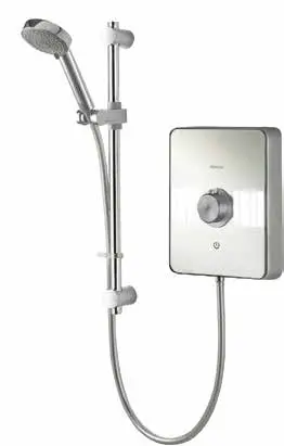
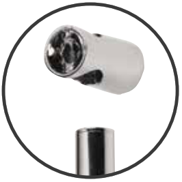
COMPONENTS

 In addition to this installation guide, it is essential that the written instructions are read and understood and that you have all the necessary components before commencing installation. Failure to install the product in accordance with these instructions may adversely affect the warranty terms and conditions. Do not undertake any part of this installation unless you are qualified to do so. Prior to starting, ensure that you are familiar with the necessary plumbing and electrical regulations and legislation required to install the product correctly and safely.The Lumi™ Electric is supplied with universal fittings intended to secure the unit to a suitable wall.
IMPORTANT INFORMATION
Safety informationThis appliance can be used by children aged from 3 years and above and persons with reduced physical, sensory or mental capabilities or lack of experience and knowledge if they have been given supervision or instruction concerning the use of the appliance in a safe way and understand the hazards involved.Children shall not play with the appliance.Cleaning and user maintenance shall not be made by children without supervision.The spray head must be descaled regularly.This appliance is intended to be permanently connected to the water mains and not connected by a hose set.A suitable double pole isolation switch for supply disconnections must be incorporated in the fixed wiring circuit, in accordance with current wiring rules. See the Electrical Installation section for further details. This product must be installed by a competent person in accordance with all relevant current Water Supply Regulations.ALL SHOWERS REQUIRING AN ELECTRICAL CONNECTION MUST BE INSTALLED BY A QUALIFIED PERSON FOLLOWING THE LATEST REVISION OF BS 7671 (WIRING REGULATIONS) AND CERTIFIED TO CURRENT BUILDING REGULATIONS.WITH REFERENCE TO BUILDING REGULATION PART P, ANY NEW INSTALLATION OR REPLACEMENT PRODUCT INSTALLATION WHICH IS NOT IDENTICAL TO THE PRODUCT BEING REPLACED, THE CABLE SIZES, CIRCUIT PROTECTIVE DEVICES, EARTH BONDING AND ALL OTHER REQUIREMENTS OF THE BUILDING REGULATION MUST BE ASSESSED BY A (REGISTERED) QUALIFIED ELECTRICIAN AND INSTALLED IN CONSIDERATION TO THE SITE CONDITIONS (See table below).
Introduction
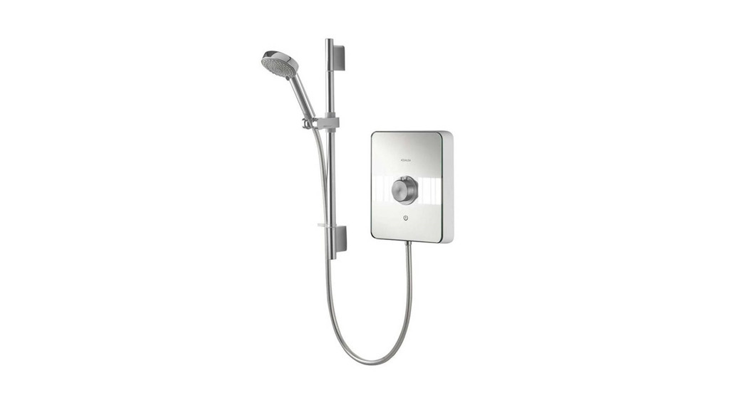
Lumi™ Electric is a surface-mounted instantaneous electric shower unit that is available in a choice of performance ratings – 8.5kW, 9.5kW, and 10.5kW available in Chrome or White/chrome.Lumi™ Electric features an illuminated panel.Lumi™ Electric’s patented Over Temperature Protection (OTP) device ensures safer comfortable showering whilst the shower provides endless economical showering as it imposes no demand on stored hot water.Aqualisa products are supplied complete with a 1-year guarantee that can be upgraded by registering the product with Aqualisa. See www.aqualisa.co.uk/guarantee for details.
| Shower Rating 0 240V | 8.5KW | 9.5KW | 10.5KW | ||||
| Nominal current @ 240V | 35.4A | 39.6A | 43.8A | ||||
| MCB rating | 40A | 40A | 45/50A | ||||
| Cartridge fuse | 40/45A | 40/45A | 45A | ||||
| Min cablesize mm2 | Max cablerun in m | Min cablesize mm’ | Max cablerun in m | Min cablesize mm’ | Max cablerun in m | ||
| Type of cable run | Installed in an insulated wall | 10 | 61 | 10 | 55 | 10 | 50 |
| Conduit or trunking | 6 | 37 | 10 | 55 | 10 | 50 | |
| Clipped director buried inuninsulated wall | 6 | 37 | 6 | 33 | 10 | 50 |
Notes:
- Cable selection is dependant on de-rating factors detailed in the electrical rating section.
- In certain installations, the combination of low voltage and extended cable lengths may result in loss of power and a consequential reduction in flow rates.
- Cable sizes detailed are the minimum acceptable sizes. Sizes greater than these shown above may be used and should be used if cable runs are greater than indicated (above cable runs are based on a maximum 9.6V drop).
- Rewirable fuses are not recommended and not covered by this table.
- Installation should be carried out by a qualified person. Please refer to BS7671 (Wiring Regulations) if in doubt.
- A 16mm² cable may be required for longer cable runs.Cables that are chased into the wall must be protected by the use of conduit or sheathing. Surface-mounted cables must also be protected by a suitable approved conduit.Before removing the shower heater cover, ensure the heater is isolated from the electric mains.Lumi™ Electric is suitable for household use only.
FlushingSome modern fluxes can be extremely corrosive and, if left in contact, will attack the working parts of this unit. All soldering must be completed and the pipework thoroughly flushed out in accordance with current Water Supply Regulations prior to connection of the product.ConnectionsLumi™ Electric is suitable for use with 15mm British Standard pipe and should be connected using a 15mm compression fitting (not supplied). Lumi™ Electric is suitable for bottom or rear entry pipework and bottom or rear entry cable. Supply lines should be flushed clear of any debris prior to installation of the unit.Isolating valvesA suitable full bore isolation valve must be fitted to the incoming supply in accordance with the current Water Supply Regulations and our terms of the warranty.SitingRefer to the positioning guideline. The Lumi™ Electric unit must be mounted on a flat, vertical finished wall with the hose outlet pointing downwards. Any distortion of the backplate may result in the unit not working. Spacers are provided and are attached to the service tunnel. If required, these can be used to enable the unit to be fitted to an uneven wall surface, if required.
![]() DO NOT tile up to the unit or apply silicone. The shower is spaced off the wall by integral pillars to allow air circulation around the unit.The casing must not be sited where it is subjected to continuous spray from the showerhead. The Lumi™ Electric should not be sited in any situation where it is likely to freeze.WARNING DO NOT SWITCH THE SHOWER ON IF THERE IS A POSSIBILITY THAT THE SHOWER COULD BE FROZEN. If you have switched the shower on, SWITCH OFF IMMEDIATELY.Please refer to the troubleshooting guide.
DO NOT tile up to the unit or apply silicone. The shower is spaced off the wall by integral pillars to allow air circulation around the unit.The casing must not be sited where it is subjected to continuous spray from the showerhead. The Lumi™ Electric should not be sited in any situation where it is likely to freeze.WARNING DO NOT SWITCH THE SHOWER ON IF THERE IS A POSSIBILITY THAT THE SHOWER COULD BE FROZEN. If you have switched the shower on, SWITCH OFF IMMEDIATELY.Please refer to the troubleshooting guide.
Water pressure
Check that the dynamic (running) water pressure to the Lumi™ Electric is adequate. Using the pressure test adaptor provided, follow the pressure test adaptor fitting and user instructions to ensure the water pressure to the shower is within the minimum and maximum requirements. The pressure test adaptor must be left with the customer.Max: 1.0MPa (10 bar)Min: 0.09MPa (0.9 bar) at a flow rate of 8 liters per minuteThe Lumi™ Electric shower is designed to control static pressure up to 1.0MPa (10 bar). Where pressures are likely to exceed 1.0MPa (10 bar), a pressure-reducing valve must be fitted into the incoming mains supply. A setting of 0.3MPa (3 bar) is recommended. It should be noted that daytime pressures approaching 8 bar can rise above the statedmaximum overnight.A suitable pressure-reducing valve is available from Aqualisa.The use of other services connected to the water supply to the shower unit may cause the water pressure to drop below the minimum required. This should therefore be taken into consideration.Pressure relief device (PRD)To meet European standards, the shower unit features an integral pressure relief device ( PRD).DO NOT operate the shower with a damaged or kinked hose or blocked shower head, as this can cause the PRD to operate. Failure to follow this instruction will invalidate the guarantee.The shower will only function correctly with the hose and handset provided (see shower head installation instructions overleaf). Failure to do so may result in the operation of the PRD and will invalidate the guarantee.Please fully commission the shower prior to use following the shower commissioning procedure detailed overleaf. Failure to do so could cause the PRD to operate and will invalidate the guarantee.The shower unit must be sited over a bath or shower tray as in the event of the PRD operating, water will drain from the bottom of the shower unit.Inspection & maintenanceIn the interests of safety, we recommend the Lumi™ Electric and its electrical installation are checked by a qualified electrician at least every 2 years.Cleaning the filter should only be completed by a qualified person. Please refer to the instructions on how to clean the filter, overleaf.After installationFamiliarise the end-user with the operation of this product and hand them this guide. Complete and post the guarantee card or register online at www.aqualisa.co.uk.Declaration of ConformityAqualisa Products Limited declares that the Lumi™ Electric shower complies with the essential requirements and other relevant provisions of the Low Voltage Directive (2014/35/EU) and the EMC Directive (2014/30/EU). The PRD provides a degree of shower unit protection should an excessive build-up of pressure occur within the shower.
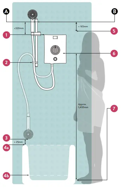
POSITIONING GUIDELINE
This product must be installed by a competent person in accordance with all current Water Supply Regulations.
Appendix
- Distance between the top of the chrome rail and the top of the shower engine is a maximum of 320mm.
- hose retaining ring.
- 25mm minimum.4a. Bath spillover level.4b. Shower tray spillover level.
- Distance between the height of user and top of chrome rail is a maximum of 165mm (Average person height 1,750mm).
- If A & B measurement guidelines are followed, the pipework entry point for the shower will be approximately 1,400mm from the standing level in the shower tray or bath.
- The depth/height of the shower tray or bath must be taken into consideration when completing the first fix.
TROUBLESHOOTING
| Symptom | Possible cause | Action |
| No flow or not enough flow. | Power failure (light does not illuminate). | Check power supply, consult an electrician. |
| incorrect use of touch switch. | See user instructions. | |
| The water control knob is turned fully clockwise. | Turn flow control knob anticlockwise. | |
| The water is turned off at the mains or servicing valve. | Ensure water is turned fully on at the mains and at servicing valve in supply. | |
| THE SHOWER UNIT IS SUSPECTED OF BEING FROZEN. | If so, DO NOT USE.i) Switch off immediately at the electrical isolating switch.ii) Turn the water off at servicing valve (if fitted) or at the stop cock.iii) Contact our Customer Service Department. | |
| There may be an outlet blockage. | Disconnect the handset from the hose and run the shower.i) If water flows, then the handset is blocked with scale or debris. Clean the handset and spray plate thoroughly.ii) If the water does not flow, remove the hose from the shower outlet.a) If the water flows, the hose is blocked. This could be due to damage, severe kinking or even an obstruction. Replace with a new hose.b) If the water does not flow, there is a blockage in the plumbing to the shower, the filter, or the shower itself. Contact our Customer Service Department if the shower is considered to be the problem. |
| Symptom | Possible cause | Action |
| Flow adequate but water too cold. | Blocked inlet filter. | Remove the filter for inspection.PLEASE REFER TO THE CLEANING AND MAINTENANCE SECTION. |
| Restricted operation of the flow control knob. | Remove the front cover and check the operation of a knob. | |
| Water flow is too high. | Reduce the flow by turning the water control knob towards the hot temperature markings (clockwise) slowly. | |
| Second stage thermal trip operated. | This is a nonserviceable part, the shower must be replaced. | |
| Water too hot. | Water flow too low. | a) Increase the flow by turning the water control knob towards the cold temperature markings (anticlockwise) slowly.b) Ensure that the stop cock and servicing valve are fully open. If so, ask the installer or the local water authority to check that the running pressure is above the minimum requirement (see Pressures section overleaf). This may be apparent during periods of high demand or when other outlets are used. |
| Spray plate and/or hose blocked with scale or debris. | Clean the handset spray plate. Remove the hose and check for restrictions. Run without the hose attached to check the temperature. | |
| Incoming main water pressure or flow too low. | After confirming that the filter is clear, check withthe installer or local water authority. | |
| Seasonal conditions – Warmer inlet water temperature. | Set temperature dial to the coolest setting.Note: Seasonal water conditions influence the temperature range of the shower. This applies to all-electric showers. |
| Symptom | Possible cause | Action |
| Water runs from around the hose. | A pressure relief device (PRD) has operated due to excess pressure build-up.Hose incorrectly fitted. | Turn off the electrical isolating switch and water servicing valve and contact our Customer services department.Ensure the hose washer is fitted and the hose is connected correctly and tightly. |
| Fluctuating watertemperature. | Incorrect handset or hose fitting.Water pressure to shower is low or unstable.The thermal cut-out is operating, normally making a ‘click’ sound.The over-temperature protection device has been activated. | Use only the handset and hose provided.Check inlet requirements – see Pressures section, and ensure no other main water devices are being used while showering.Increase the flow by turning the water control knob in the cold temperature direction (anticlockwise). Clean the handset and spray plate.Increase the flow by turning the water control knob in the cold temperature direction (anticlockwise). Clean the handset and spray plate. |
| Poor spray pattern. | Incorrect handset or hose fitting.Multi-pattern handset incorrectly set.Low water inlet temperature.Low voltage. | Use only the handset and hose provided.Adjust spray plate to improve the pattern.The flow rate will naturally be lower when the inlet temperature is low, this applies to all-electric showers.Consult electrician. |
| Temperature low | Seasonal conditions | During the winter months, the temperature of the incoming mains water supply is low. Turn the dial to a warmer setting and adjust the spray pattern on theshower head. |
INSTALLATION
PIPEWORK
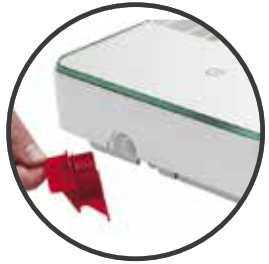
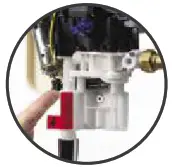
- Carefully remove the red outlet plug assembly.Note: Water will be present in the unit due to production testing.

- Remove the securing screws at the top and bottom of the Lumi™ Electric front casing and carefully lift the casing away from the backplate assembly. Carefully detach the solenoid connector and pull the front casing clear.
- Carefully unscrew and remove the service tunnel and set it aside. (This may be required if retrofitting this shower in place of an existing one).
- Refer to positioning guideline diagram overleaf.Tape the template provided onto the finished wall surface in the desired position and mark the required 3 fixing points. Drill and prepare the fixings holes using the fixing kit provided, if suitable.Where applicable, use fixing point 2a for new installations. Utilize fixing point 2b for like-for-like replacements. Check backplate fixing points prior to drilling.The product is not suitable for top entry.
- Flush through the water supply pipe allowing it to discharge safely to waste.
- Pipework connection must be made using a 15mm compression elbow (not supplied) for bottom or rear entry. A copper olive is supplied, located on the shower inlet stub, and should be fitted into the compression elbow prior to the elbow being connected.Rear entry.The wall must be sufficiently chased out around the pipe and cable to allow room for the nut on the compression elbow to be recessed into the wall. Failure to do so will result in distorting the backplate and a poor fitting front cover. The pipework must be connected to the elbow prior to fitting the shower unit to the wall.
- Turn on the water supply to the shower unit and check for leaks upstream of the shower unit. If all is sound turn off the water supply to the shower unit. Ensure the water pressure to the shower unit is within the minimum and maximum requirements by following the pressure testing procedure – refer to the cleaning and maintenance section. Pressure and flow readings must be recorded within the table in the commissioning section of this guide.
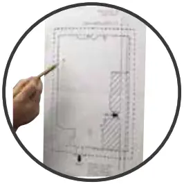 Where applicable, use fixing point 2a for new installations. Utilize fixing point 2b for like-for-like replacements. Check backplate fixing points prior to drilling.
ELECTRICAL
BEFORE ANY ELECTRICAL CONNECTION IS ATTEMPTED, THE ELECTRICITY SUPPLY MUST BE TURNED OFF AT THE MAIN SWITCH. FAILURE TO DO SO COULD RESULT IN ELECTROCUTIONThe electrical installation should be carried out by a qualified person in accordance with IEE (Institution of Electrical Engineers) wiring regulations (BS 7671)THIS APPLIANCE MUST BE EARTHED. IN THE INTERESTS OF ELECTRICAL SAFETY, A 30mA RESIDUAL CURRENT DEVICE (RCD) SHOULD BE INSTALLED IN ALL UK 230-240V ELECTRIC SHOWERS AND PUMPED CIRCUITS. THIS MAY BE PART OF A CONSUMER UNIT OR A SEPARATE UNITA suitably rated double-pole isolating switch for supply disconnection must be incorporated in the fixed wiring circuit in accordance with current wiring rules. This must have a mechanical indicator showing when the switch is in the OFF position. A neon lamp alone is not sufficient. (See the electrical rating chart for minimum switch rating). If it is fitted in the bathroom it must be the cord-operated type. The switch must be readily accessible and clearly identifiable in zone 3, i.e. at 0.6metres horizontally from the shower cubicle or edge of the bath, or located above zone 2 (i.e. adjacent to the shower cubicle or bath, but at least 2.25metres from the floor) as detailed below. This requirement does not apply to the pull cord from the switch.Where shower cubicles are located in rooms other than bathrooms, any socket outlet in the room must be situated at least 3 meters from the shower cubicle and protected by a 30mA RCD.

MAINS VOLTAGE CONNECTION
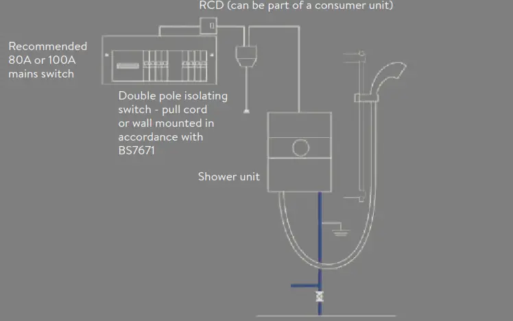
Please refer to the typical system diagram.The following notes are for guidance only – the installation must comply with current regulations.
- The shower unit must only be connected to a 230-240V AC supply.
- Before making electrical connections within the installation make sure that no terminal is live. If in doubt, switch off the whole installation at the consumer unit or switch fuse (where fitted).
- The shower unit must be connected to its own independent electrical circuit.It MUST NOT be connected to a ring main, spur, socket outlet, or lighting circuit, otherwise, the circuit will overheat.
- Check that the consumer unit (main fuse box):A. Has the main switch rating of 80A or above.B. Has a spare fuse way that will take the fuse/mcb (miniature circuit breaker) you need to fit.If so you can wire the shower direct to the consumer unit (please refer to the typical system diagram below). (Not all consumer units accept a 35/40/45A sized fuse).
- If the consumer unit has a rating below 80A or if there is no spare fuse way, then the installation will not be straightforward. It may be necessary to install a new consumer nit to service the whole house or just the shower. This should be installed by a qualified person. It may be necessary to contact the electricity supplier to upgrade the incoming supply.
Typical system diagram
ELECTRICAL RATING
Refer to the electrical rating diagram (shown overleaf) to determine the nominal current of the shower. The current rating of the supply cable must be at least that of the shower itself.Use the rating chart to choose a fuse or CB with a rating of less than that of your chosen cable.WE STRONGLY RECOMMEND NOT USING REWIRABLE FUSES.The current rating will be reduced if the cable is to be:A. Bunched with othersB. In an ambient temperature above 40ºCC. In an insulating wall or within thermal insulation, e.g. loft insulation.D. In any other unusual positionIf in doubt about any aspect of electrical installation, consult a qualified electrical engineer or the electricity supplier.WIRING
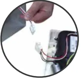
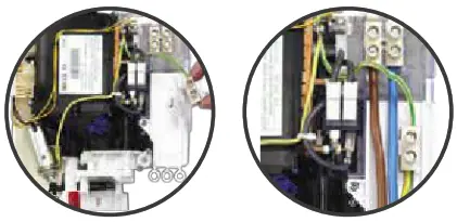
- For most installations the removable service tunnel will not be required, enabling the earth connection to be made in the top right-hand corner of the unit as illustrated.If retro-fitting the unit to an existing shower where the wiring cannot be connected as above, it may be necessary to utilize the service tunnel and alternative earth connection position, as described in steps two and three
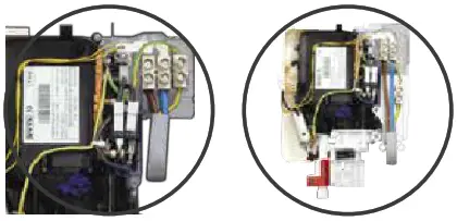
- Where required, replace the service tunnel and secure using the fixing screw provided.
- Unclip the earth terminal block and reposition it into the holder on the service tunnel.
- Any cable MUST NOT have the outer insulation stripped back beyond the bottom of the backplate or service tunnel (if used) and must be protected from water as shown. offer to the indicator guide on the service tunnel.The service tunnel MUST NOT be cut or altered in any way.

EARTH BONDINGThe installation must be earth bonded in accordance with current regulations.Where earth bonding of the premises is not evident, it may be necessary to run bonding cable back to the earth terminal at the consumer unit.FRONT COVER PREPARATIONWhen the pipework and electrical connections have been completed the front cover can be prepared to be fitted prior to beginning the commissioning procedure.
- Should your pipework or cable be bottom entry, cut away the relevant pipework and cable entry point from the bottom of the front cover, using a suitable tool.N.B. The bottom entry point is identified by an indented half lozenge shape.We recommend making good the cutout section using a round file. Ensure the cover fits over cables and pipes correctly.
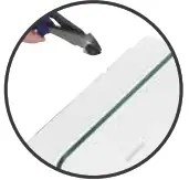 We recommend making good the cutout section using a round file. Ensure the cover fits over cables and pipes correctly.
COMMISSIONINGThis shower must be fully commissioned following the procedure detailed below before use. Failure to do so could damage the shower and invalidate the guarantee.
- Without fitting the showerhead, fit the hose washer into the hose and attach it to the shower outlet to allow the water to discharge safely to waste.
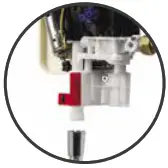
- Ensuring the electric supply remains isolated, turn on the water supplies. Push the solenoid piston up until the water runs through and out of the hose for a few seconds before releasing the piston.
- Turn the flow control valve on the shower unit to the full cold (6 o’clock position). Turn the flow control lever on the front casing to the full cold position (9 o’clock). The flow control valve and lever are keyed and must be correctly positioned in order for the cover to fit.
- Hold the cover next to the shower unit on the wall and carefully attach the two solenoid connectors. Place the solenoid connector block into the saddle within the shower unit and neatly tuck the wires into the recess provided.
- Carefully offer the cover onto the backplate assembly ensuring the wires are not trapped. The control knob, in the full cold position, may have to be slightly adjusted to enable the key ways to align.
- Secure the front cover to the base plate using the 3 fixing screws taking care not to overtighten.
- Turn the flow control knob to ensure it moves smoothly (the full range of movement runs from 9 o’clock to 3 o’clock). If not, the knob may be fitted incorrectly. The shower should be commissioned with the knob in the mid position (12 o’clock).
- Turn on the power supply. Touch the start/stop icon and ensure the white LED illuminates (see user instructions).
- Slowly turn the flow control knob towards the hot direction. The heater elements should now be hotter and the temperature of the spray should increase.
- Adjust the flow control knob to provide the desired temperature. Allow a few seconds aftereach adjustment for the temperature to stabilize. A cool shower can be achieved with the flow control knob set towards the cold direction. The temperature achieved will depend on the incoming water temperature and pressure.


SHOWER KITRefer to positioning guideline diagram overleaf.The showerhead should be sited close to the shower unit, not necessarily on the same wall, but not sothat the unit is subjected to continuous spray.THE SHOWER OUTLET, HOSE, AND HANDSET ACT AS A VENT. THEY MUST NOT BE BLOCKED, OBSTRUCTED OR BE CONNECTED TO ANY SITTING NOT APPROVED BY US. THE USE OF UNAPPROVED ACCESSORIES MAY INVALIDATE THE GUARANTEE AND MAY AFFECT THE PERFORMANCE AND SAFETY OF THE UNIT.
- Prepare two fixing holes up to a maximum of 407mm apart.N.B. The rail kit supplied utilizes a floating bracket that can be positioned to suit existing screw holes on retrofit installations.
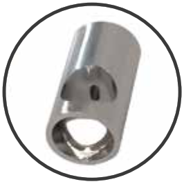
- Pass the rail through the handset holder while keeping the slider levers depressed.N.B. The bottom of the rail is identified by two holes; one large and one small.
- Carefully slide the gel hook onto the rail under the handset holder.
- Refer to positioning guideline diagram overleaf.Current water supply regulations state that the handset should not be allowed to pass a point 25mm above the spill-over level of the bath or shower tray. If this cannot be achieved, the hose must be passed through the gel hook which has also been designed to be utilized as a hose restraint.
- Secure the top rail bracket into position on the finished wall surface using the short wall screw.
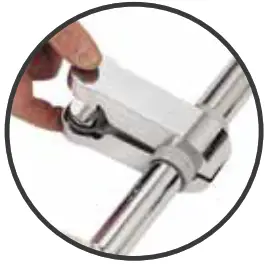
- Slide the bottom rail bracket onto the bottom of the rail.
- Slide the rail assembly up through the top rail bracket.
- Align the fixing hole of the bottom bracket with the corresponding holes on the rail assembly, ensuring the smaller-sized hole on the rail is closest to the wall. Secure the bottom rail bracket to the wall using the longwall screw.
- Place the rail end caps into both brackets and push firmly into position.
- Pass the hose through the gel hook.
- Ensuring the hose washers are in the correct position, depress the anti-swivel locking button on the handset, and secure the handset to the hose. Place the handset into the handset holder.


PRESSURE AND FLOW READINGSTHE BELOW TABLE IS TO BE COMPLETED BY THE INSTALLER UPON INSTALLATION.
| Installation Reading | 2nd Reading (If applicable) | 3rd Reading (If applicable) |
| Date: | ||
| Flow rate:(Litres per minute) | ||
| Static pressure:(BAR) | ||
| Working pressure:(BAR) |
This guide must be handed to the customer on installation completion.The pressure test adaptor MUST be left with the customer, should future readings be necessary.If static or working pressures are too low (less than 0.9 Bar), contact your local water authority.Flow rate to be taken in the full cold position with the shower head and hose attached.
USER INSTRUCTIONS
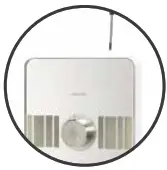
Aqualisa has been at the forefront of showering technology for 40 years specializing in solutions that make showering an everyday pleasure. Whilst striving to improve our products, from time to time we make changes to the functions and operation to improve the customer experience.Operating the showerIMPORTANT: As with all-electric showers for safety purposes, we advise isolating the power to your Lumi™ when it is not in use.The Lumi™ features a mirrored glass fascia with an illuminated front panel and a white LED power indicator above the start-stop symbol.To start the showerTurn on your isolating switch.Touch the start/stop symbol for approximately one second and release, the light panel, and the power LED will illuminate to indicate a successful touch. (If the light panel illuminates but not the power LED, then the touch has not been effective). Pressing and holding will result in the panel illuminating, but no flow of water.To set the temperatureWith the shower running, rotate the control knob to give the desired temperature; clockwise for warmer and anticlockwise for cooler. Allow a few seconds after each adjustment for the temperature to stabilize.WARNING: ALWAYS CHECK THE SHOWERING TEMPERATURE BEFORE STEPPING INTO THE SHOWER. IT WILL TAKE APPROXIMATELY 20 SECONDS TO REACH A STABLE TEMPERATURE.To stop the showerTouch the start/stop symbol for approximately one second and release, both the light panel and the power LED will go out to indicate a successful touch, the water will continue to run for a short period of time before shutting down (this is the phased shutdown function).(If the light panel goes out temporarily but not the power LED, then the touch has not been effective).Pressing and holding will result in the unit not turning off.IMPORTANT: Turn off your isolating switch.N.B. The phased shutdown feature of this shower requires the shower to run on for a few seconds after the shower is turned off. This is a safety feature that flushes any residual hot water out of the shower unit to protect the next user.N.B. The shower will run for a maximum of 20 minutes continual use before automatically turning off to safeguard the internal working elements. The product can be restarted as soon as desired.Safety, Maintenance, and CareIMPORTANT: As with all-electric showers for safety purposes, we advise isolating the power to your Lumi™ when it is not in use.Do not place items on top of the shower, e.g. soap, shower gel, shampoo bottles, etc.To maintain the look and function of your shower, clean regularly;Ensure the power is isolated to the shower when cleaning to avoid the shower accidentally turning on.To maximize performance and temperature stability ensure the shower head jets are cleaned regularly to prevent limescale building up.The shower will only function correctly with the hose and handset provided (see shower head installation instructions). Failure to do so may result in the operation of the PRD and will invalidate the guarantee.Showerhead operationNEVER ATTEMPT TO MAKE ANY ADJUSTMENT TO THE SHOWERHEAD BY PULLING ON THE SHOWER HOSE.
- To select the preferred height for the showerhead, depress the handset holder levers fully to enable the slider to be moved up or down the rail.
- Angular adjustment is made by carefully but firmly pulling forwards or pushing back the shower head against the knuckle in the holder.
- To select the desired spray pattern rotate the shower spray plate clockwise or anti-clockwise.
General notesIf you have any questions at any stage during the fitting of this product, please contact the Aqualisa customer helpline on 01959 560010.Cleaning & maintenanceYour Lumi™ Electric unit should be cleaned using only a soft cloth and washing up liquid.DO NOT USE ABRASIVE CLEANERSTo reduce the requirement for chemical descaling in hard water areas, the showerhead incorporates rub clean teats. Any scale build-up that may occur in any of the holes can be broken down by gently rubbing the flexible tips of the jets during use. This procedure should be completed regularly, as often as once a week in some hard water areas as scale build-up can affect the spray pattern and cause the shower to perform poorly.Should chemical descaling of the head become necessary, remove the showerhead and fully immerse in a mild proprietary descent.It is imperative that descaling is carried out in accordance with the manufacturer’s instructions, substances that are not suitable for plastics and electroplated surfaces must not be used. The shower hose and handset can only be replaced with genuine Aqualisa parts.Cleaning the filterCleaning the filter should only be completed by a qualified person.
- Turn the shower electrical isolating switch off.
- Isolate the water supply to the shower.
- Carefully remove fixing screws from the top and bottom of the front cover.Carefully pull the front cover away from the unit ensuring the solenoid connector block is detached.
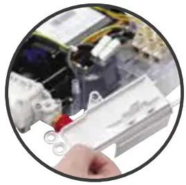
- Unscrew the two screws on the filter protective cover and remove the filter assembly.
- Remove the filter assembly and clean as necessary.
- Refit the filter assembly and protective cover. Reassemble the unit in reverse of the above procedure.
Pressure test adaptor fitting and user instructionsLumi™ Electric requires the following dynamic (running) water pressure: Maximum: 1.0 MPa (10bar) Minimum: 0.09 MPa (0.9bar) at a flow rate of 8lpm To ensure the water pressure to the shower is adequate, we recommend adopting the following procedure:
- Isolate the electrical supply to the shower.
- Isolate the water supply to the shower.
- Remove the fixing screws from the top and bottom of the front cover. Carefully detach the solenoid connector and pull the front cover clear.
- Unscrew the two fixing screws on the filter and remove the filter assembly.
- Replace the filter assembly with the pressure test adaptor (supplied) and secure it into place using the filter assembly fixing screws.
- Connect a pressure testing device (not supplied) to the adaptor.
- Ensuring the electrical supply remains isolated, turn on the water supply to the shower.
- Push the solenoid piston up until the water runs through to the shower unit.
- Check that the reading on the pressure testing device is within the minimum and maximum requirements stated above. Record both the static and working pressures in the PRESSURE AND FLOW READINGS table (left).
- Isolate the water supply to the shower.
- Detach the pressure test device and remove the adaptor.
- Refit the filter assembly and secure using the fixing screws.
- The customer should keep the pressure test adaptor in a safe place for future use.
- Reassemble the unit in reverse of the above procedure and turn on the water and electrical supplies to the shower unit.
![]()
Aqualisa Products LimitedThe Flyers WayWesterham Kent TN16 1DECustomer Helpline: 01959 560010Brochure Hotline: 0800 652 3669Website: www.aqualisa.co.ukEmail: [email protected]Republic of IrelandSales inquiries: 01-864-3363Service inquiries: 01-844-3212
 Please note that calls may be recorded for training and quality purposes.The company reserves the right to alter, change or modify the product specifications without prior warning.™Trademark of Aqualisa Products Limited.

Part No: 704716 Issue 02 Feb 21
References
[xyz-ips snippet=”download-snippet”]