Owner’s GuideTH131Electronic thermostat
Before you start
Read the entire document
- Installation must be carried out by a certified electrician and must comply with national and local electrical codes.
- To prevent severe shock or electrocution, always cut the power at the service panel before working with the wiring.
- This thermostat should be connected to a circuit equipped with a fuse or a circuit breaker. It must be installed on a certified electrical box.
- Do NOT install the thermostat in an area where it can be exposed to water or rain.
- Install the thermostat on an inside wall facing the heating system.
- Avoid locations where there are air drafts (top of the staircase, air outlet), dead air spots (behind a door), direct sunlight, or concealedchimneys or stovepipes.
- For a new installation, choose a location about 1.5 m (5 ft) above the floor.
- Keep the thermostat’s top and bottom air vents (openings) clean and unobstructed at all times.
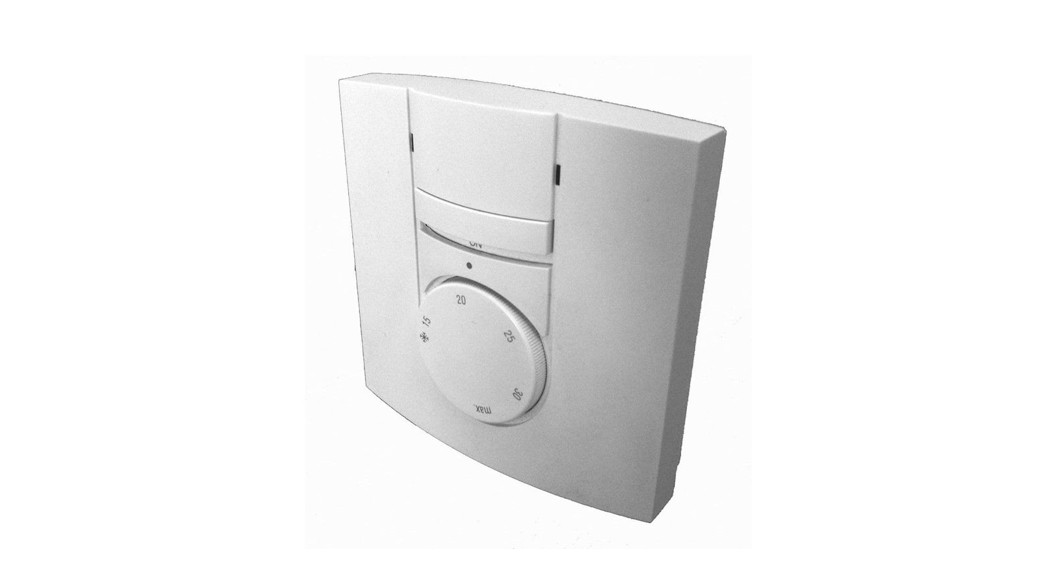
About your thermostat
The thermostat provides three temperature control modes:
| A mode: | • controls the ambient temperature |
| F mode: | • controls the floor temperature |
| AF mode: | • controls the ambient temperature and limits the floor temperature |
See page 8 on how to select the temperature control mode setting.
Supplied Parts
- One thermostat
- One floor sensor (for AF and F models only)
- One wall plate (optional, in some countries only)
Controls
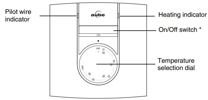
* Use this switch to disable heating (e.g. in the summer).
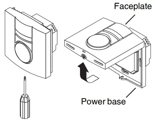
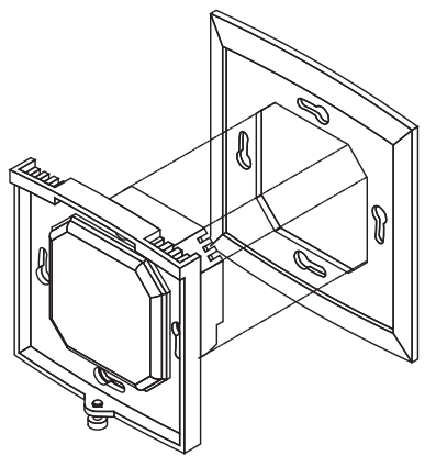
Installation
- Turn off power to the heating system at the main electrical panel.
- Loosen the bottom screw and remove the thermostat’s faceplate from the power base. The screw cannot be completely removed.

- Before making the connections, make sure that the power base covers the electrical box entirely. If not, install the supplied wall plate at the back of the power base.
- Connect the wires (see page 6).
- Push wires into the electrical box and secure the power base to the electrical box. The head of the screw must be less than 2 mm thick.
- Select the control mode (see page 8).
- Set the minimum and maximum temperature limits (see page 9).
- Install the faceplate on the power base.
- Return power to the heating system.


Connections

| Power | Terminals 1 & 5 |
| Load | Terminals 2 & 4 (see note 1) |
| Pilot Wire | Terminal 3 (see note 2) |
| Floor sensor | Terminals 6 & 7; no polarity (see note 3) |
NOTE 1 If a contactor is used between the thermostat and the load, install a snubber at the contactor’s coil terminal to ensure the proper operation of the thermostat.NOTE 2 Optional (see page 10).NOTE 3 For the proper operation of the thermostat, the floor sensor must be centered between two heater wires having a maximum temperature of 80°C (176°F). The floor sensor wire must not cross any heater wire or be placed close to it.NOTE 4 Ensure that the wires are tightly secured to the terminals. Apply a minimum torque of 0.5 Nm (4.4 Lb/in) when tightening the screws.NOTE 5 The terminals are designed to handle a cross-section of wire measuring 0.33 to 3.1 mm2.
Control mode
Position the switch, on the back of the thermostat faceplate, according to your application.
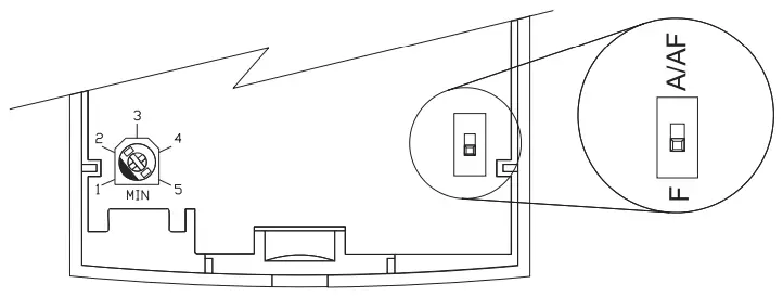
| Type | SwitchPosition | Application |
| A | Up | Controls the ambient temperature |
| F | Down | Controls the floor temperature |
| AF | Up | Controls the ambient temperature and limits thefloor temperature |
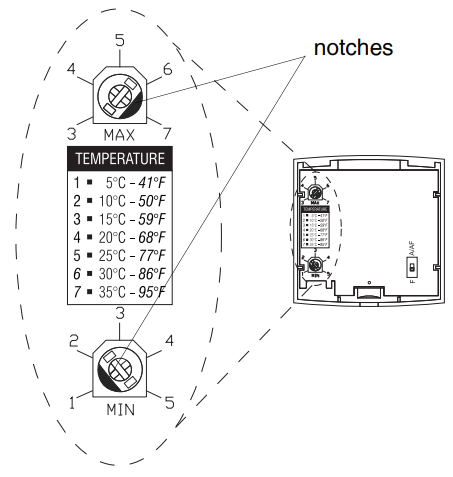
Minimum and maximum limits
Use two potentiometers on the back of the thermostat faceplate to set the minimum and maximum temperature limits. Use a flat-tip screwdriver to rotate the potentiometers until the notch points to the desired temperature limit.
Depending on your application, the potentiometers limit the following temperature:
- ambient temperature (A)
- floor temperature (F or AF)
Pilot wire orders
TH131 accepts the six following pilot wire orders.
| ORDER | SIGNAL | DESCRIPTION |
| Comfort | No signal | Maintain temperature at setpoint |
| Reduced setpoint(3.5k setback) |  |
Maintain temperature at 3.5°C below the setpoint |
| frost protection | 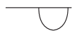 |
Maintain temperature at 7°C |
| Off | Stop heating | |
| 1k setback | 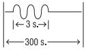 |
Maintain temperature at 1°C below the setpoint |
| 2k setback | 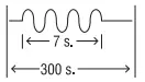 |
Maintain temperature at 2°C below the setpoint |
Technical specifications
Supply: 230 VAC, 50 HzMaximum Load: 15 A or 3450 Watts (resistive only)Setpoint range: 7°C, 15°C to 35°C (45°F, 59°F to 95°F)Minimum temperature limit: 5°C to 25°C (41°F to 77°F)Maximum temperature limit: 15°C to 35°C (59°F to 95°F)Accuracy: ± 0.2°C (0.36°F)Storage temperature: -20°C to 50°C (-4°F to 120°F)Heating cycle length: 15 minutesSoftware: Class AAutomatic action: Type 1.BController: ElectronicProtection index: IP20Conformity: EN60730-1 / EN50081-1 / EN50082-2Protection: Class 2Environment: Normally pollutedSize (H • W • D) : 78.9 x 78.9 x 16.3 mm (3.1 x 3.1 x 0.64 in.)Environmental Compliance: RoHS-Directive 2011/65/EU
Warranty
Resideo warrants this product, excluding battery, to be free from defects in workmanship or materials, under normal use and service, for a period of three (3) years from the date of first purchase by the original purchaser. If at any time during the warranty period the product is determined to be defective due to workmanship or materials, Resideo shall repair or replace it (at Resideo’s option).
If the product is defective,
- return it, with a bill of sale or other dated proof of purchase, to the place from which you purchased it; or
- call Resideo Customer Care at 1-800-468-1502. Customer Care will make the determination whether the product should be returned to the following address: Resideo Return Goods, 1985 Douglas Dr. N., Golden Valley, MN 55422, or whether a replacement product can be sent to you. This warranty does not cover removal or reinstallation costs. This warranty shall not apply if it is shown by Resideo that the defect was caused by damage that occurred while the product was in the possession of a consumer.
Resideo’s sole responsibility shall be to repair or replace the product within the terms stated above. RESIDEO SHALL NOT BE LIABLE FOR ANY LOSS OR DAMAGE OF ANY KIND, INCLUDING ANY INCIDENTAL OR CONSEQUENTIAL DAMAGES RESULTING, DIRECTLY OR INDIRECTLY, FROM ANY BREACH OF ANY WARRANTY, EXPRESS OR IMPLIED, OR ANY OTHER FAILURE OF THIS PRODUCT.Some states do not allow the exclusion or limitation of incidental or consequential damages, so this limitation may not apply to you.THIS WARRANTY IS THE ONLY EXPRESS WARRANTY RESIDE MAKES ON THIS PRODUCT. THE DURATION OF ANY IMPLIED WARRANTIES, INCLUDING THE WARRANTIES OF MERCHANTABILITY AND FITNESS FOR A PARTICULAR PURPOSE, IS HEREBY LIMITED TO THE THREE-YEAR DURATION OF THIS WARRANTY. Some states do not allow limitations on how long an implied warranty lasts, so the above limitation may not apply to you.This warranty gives you specific legal rights, and you may have other rights which vary from state to state. If you have any questions concerning this warranty, please write Resideo Customer Care, 1985 Douglas Dr, Golden Valley, MN 55422 or call 1-800-468-1502.

 Resideo Technologies, Inc.1985 Douglas Drive North, Golden Valley, MN 5542233-00048EFS—03 M.S. Rev. 05-20 | Printed in the United States
 report this ad
© 2020 Resideo Technologies, Inc. All rights reserved.The Honeywell Home trademark is used under license from Honeywell International, Inc.This product is manufactured by Resideo Technologies, Inc. and its affiliates.
[xyz-ips snippet=”download-snippet”]