AWM6036UUSB POWERED UHF WIRELESS MICROPHONE SYSTEM WITH ADJUSTABLE FREQUENCIESOWNER’S MANUAL
Thank you for purchasing the Audio2000’S® USB-powered UHF wireless microphone system with adjustable frequencies! For the best results and the utmost satisfaction from your new unit, please read this manual thoroughly, and retain it for future reference. For more information, please visit our website (www.audio2000s.com).
WARNING* TO PREVENT FIRE OR SHOCK HAZARDS, DO NOT EXPOSE THIS APPLIANCE TO RAIN OR MOISTURE. * THIS APPLIANCE SHALL NOT BE EXPOSED TO DRIPPING OR SPLASHING WATER AND THAT NO OBJECT FILLED WITH LIQUIDS SUCH AS VASES SHALL BE PLACED ON THE APPARATUS.
 This lightning flash with an arrowhead symbol, within an equilateral triangle, is intended to alert the user to the presence of uninsulated “dangerous voltage” within the product’s enclosure that may be of sufficient magnitude to constitute a risk of electric shock to persons. This lightning flash with an arrowhead symbol, within an equilateral triangle, is intended to alert the user to the presence of uninsulated “dangerous voltage” within the product’s enclosure that may be of sufficient magnitude to constitute a risk of electric shock to persons. |
 Warning: To reduce the risk of electric shock, do not remove cover(or back)no user-serviceable parts inside. Refer servicing to qualified service personnel. Warning: To reduce the risk of electric shock, do not remove cover(or back)no user-serviceable parts inside. Refer servicing to qualified service personnel. |
The exclamation point within an equilateral triangle is intended to alert the user to the presence of important operating and maintenance (servicing) instructions in the literature accompanying the appliance. |
IMPORTANT SAFETY INSTRUCTIONS
- Read these instructions.
- Keep these instructions.
- Heed all warnings.
- Follow all instructions.
- Do not use this apparatus near water.
- Clean only with a dry cloth.
- Do not block any ventilation openings. Install in accordance with the manufacturer’s instructions.
- Do not install near any heat sources such as radiators, heat registers, stoves, or other apparatus (including amplifiers) that produce heat.
- Do not defeat the safety purpose of the polarized or grounding-type plug. A polarized plug has two blades with one wider than the other. A grounding-type plug has two blades and a third grounding prong. The wide blade or the third prong is provided for your safety. If the provided plug does not fit into your outlet, consult an electrician for the replacement of the obsolete outlet.
- Protect the power cord from being walked on or pinched particularly at plugs, convenience receptacles, and the point where they exit from the apparatus.
- Only use attachments/accessories specified by the manufacturer.
- Use only with the cart, stand, tripod, bracket, or table specified by the manufacturer, or sold with the When a cart is used, use caution when moving the cart/apparatus combination to avoid injury from tip-over.

- Unplug this apparatus during lightning storms or when unused for long periods of time.
- Refer all servicing to qualified service personnel. Servicing is required when the apparatus has been damaged in any way, such as power-supply cord or plug is damaged, liquid has been spilled or objects have fallen into the apparatus, the apparatus has been exposed to rain or moisture, does not operate normally, or has been dropped.
- Grounding or Polarization: This product may be equipped with a polarized alternating-current line plug (a plug having one blade wider than the other). This plug will fit into the power outlet only one way. This is a safety feature. If you are unable to insert the plug fully into the outlet, try reversing the plug. If the plug should still fails to fit, contact your electrician to replace your obsolete outlet. Do not defeat the safety purpose of the polarized plug.
- Ventilation slots and openings in the cabinet are provided for ventilation and to ensure reliable operation of the product and to protect it from overheating, and these openings must not be blocked or covered.The openings should never be blocked by placing the product on a bed, sofa, rug, or another similar surface. This product should not be placed in a built-in installation such as a bookcase or rack unless proper ventilation is provided or the manufacturer’s instructions have been adhered to.
- The MAINS plug or an appliance coupler is used as the disconnect device, the disconnect device shall remain readily operable.
PRECAUTIONS
On Safety
- Operate only on designated AC power supply (120V AC in North America).
- Should any liquid or solid object fall into the cabinet, unplug the unit and have it checked by qualified personnel before operating it any further.
- Unplug the unit from the wall outlet or set the Master switch to OFF if it is not to be used for several days.
- To disconnect the cord, pull it out by the plug. Never pull the cord itself.
On Installation
- Allow adequate air circulation to prevent internal heat build-up. Do not place the unit on surfaces (rugs, blankets, etc.) or near materials (curtains, draperies) that may block the ventilation holes.
- Do not install the unit in a location near heat sources such as radiators or air ducts, or in a place subject to direct sunlight, excessive dust, mechanical vibration, or shock.
On Repackaging
Do not throw away the carton and packing materials. They make an ideal container in which to transport the unit. When shipping the unit to another location, repack it as it was originally packed at the factory.
PACKAGE CONTENTS
| Items | Quantities |
| AWR6036U ReceiverWireless Transmitters (AWX6036U)One of the Following Wireless Transmitters:Wireless Handheld MicrophoneWireless Lavalier MicrophoneWireless Headset Microphone | 1 |
| AC/DC5V Mini USB Power Supply Cable (USB Power Supply Cable) | 1 |
| 1/4″ to 1/4″ Microphone Cable | 1 |
| AA Batteries | 2 |
| Owner’s Manual | 1 |
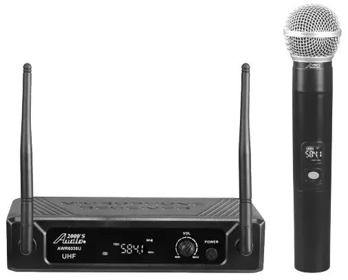
AWM6036U SYSTEM
FEATURES
- UHF Band Frequencies
- Including One of the Following Wireless Transmitters:Wireless Handheld Microphone, Wireless Lavalier Microphone, Wireless Headset Microphone
- Integrated Antenna for Effective RF Output and High Transmission Quality
- One Balanced XLR output and One Mixed Unbalanced 1/4″ Output
- One Volume Control Knob
- One AF Level Meter
- Rugged Mini Receiver Chassis
- Operating Range up to 100ft
- DC5V Power Supply
SYSTEM CONFIGURATIONS
- AWM6036U – Comprising an AWR6036U receiver and one wireless handheld microphone
- AWM6036UH – Comprising an AWR6036U receiver and one wireless headset microphone
- AWM6036UM – Comprising an AWR6036U receiver and one wireless lavalier microphone
Note: A wireless lavalier microphone of the wireless system comes with a lavalier microphone and a body-pack transmitter AWX6036UM).A wireless headset microphone of the wireless system comes with a headset microphone and a body-pack transmitter (AWX6036UH).
SYSTEM FUNCTIONS
RECEIVER (AWR6036U)
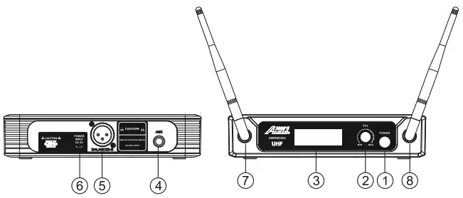
- Power On/Off Button — When the receiver power is off, press and hold this button to turn on the power. When the receiver power is on, press and hold this button to turn off the power.
- VOLUME — This is the volume control knob.
- LED Display — This display shows the frequency and AF level meter.
- Unbalanced 114″ Output
- Balanced XLR Output
- DC5V Mini USB Power Supply Jack (USB Jack).
- ANT-A — This is the antenna for channel A.
- ANT-B — This is the antenna for channel A.TRANSMITTER – HANDHELD MICROPHONE (AWX6036U)
- Power On/Off Button — When the handheld microphone power is off, press and hold this button to turn on the power. When the handheld microphone power is on, press and hold this button to turn off the power.
- LED Display — This display shows the frequencies, channels (A or B), and battery capacity.
- Frequency Adjustment Button — This button is used to adjust the frequency.
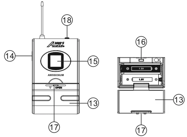
- Battery CoverTRANSMITTER – BODY-PACK (AWX6036UN or AWX6036UM)
- Battery Cover
- Power On/Off Button — When the power of the body-pack transmitter is off, press and hold this button to turn on the power. When the power of the body-pack transmitter is on, press and hold this button to turn off the power.
- LED Display — This display shows the frequencies, channels (A or B), and battery capacity.
- Frequency Adjustment Button — This button is used to adjust the frequency.
- Battery Cover Opening Point
- Microphone Input Jack — This microphone input jack is to be connected to a lavalier microphone or a headset microphone.
QUICK SETUP
A. Remove packing materialB. Install the receiver (AWR6036U)
- Place the receiver at a location at least 3.5 feet away from the ground and all the walls. Also, keep the receiver away from any electromagnetic noise sources as far away as possible.
- Plug the USB connector of the supplied USB power supply cable into the receiver’s USB Jack (6), and then plug the AC input of the supplied USB power supply cable into a 120V outlet (North America).
- Set the antennas upright. Make sure that any of the antennas is not enclosed in a large metal body.
- Connect the output of the receiver to the microphone input of a mixer or a sound In order to do so, (1) you could use the supplied microphone cable (a cable with ‘A” connectors on both ends) to connect from the unbalanced output (an ‘A” jack) to a %” microphone input on a mixer or a sound system; or (2) you could get a balanced microphone cable (cable with a male XLR connector at one end and a female XLR connector on the other end; not included in the package) to connect from the balanced output (male XLR jack) to a balanced microphone input (female XLR jack) on a mixer or a sound system.
- Both the ‘A” output and the XLR balanced output on the rear panel of the receiver are to be connected to microphone inputs only.
- Keep the receiver power off.
C. Set up the transmitter
(a) Set up the wireless handheld microphone (AWX6036U)
- Open the battery cover of the wireless handheld microphone by rotating the cover counterclockwise.
- Carefully slide the battery cover out.
- Place two 1.5V M batteries into the battery housing with the battery polarity orientations as
- Keep the power of both the receiver and this handheld microphone off. Press and hold the frequency adjustment button (11) first and then press and hold the power on/off switch (9) until the LED display (10) starts to flash. While the LED display is flashing, press the power on/off switch (1) on the receiver to turn on the receiver power. After the LED display (3) on the receiver turns on, press the frequency adjustment button (11) on this handheld microphone. The frequency of the receiver will be turned on.
- Slide the battery cover back onto the handheld microphone body.
- Once the receiver frequency is set, this receiver will be bound to this handheld microphone.
(b) Set up the body-pack transmitter (AWX6036UH or AWX6036UM)
- Open the battery cover by pulling the battery cover from the battery cover opening point (17) and then swinging the battery cover to open.
- Place two 1. 5V AA batteries into the battery housing with the battery polarity orientations as indicated.
- Keep the power of both the receiver and this body-pack transmitter off. Press and hold the frequency adjustment button (16) first and then press and hold the power on/off switch (14) until the LED display (15) starts to flash. While the LED display is flashing, press the power on/off switch (1) on the receiver to turn on the receiver power. After the LED display (3) on the receiver turns on, press the frequency adjustment button (16) on this body-pack transmitter. The frequency of the receiver will be turned on.
- Close the battery cover and connect the lavalier or headset microphone to the body-pack transmitter to form a wireless lavalier microphone or a wireless headset microphone.
- Once the receiver frequency is set, this receiver will be bound to this body-pack transmitter.
D. Set up the wireless microphone system (AWM6036U) The AWM6036U system is ready to be used.
MATCHING RECEIVER AND TRANSMITTER
- Power off all the devices.
- Long press the frequency adjustment button (11) (16) first, and long-press the power on/off button (9) (14) till the LED display (10) (15) is flashing.
- Turn on the receiver (AWR6036U), and wait 3-5 seconds.
- Re-press the frequency adjustment button (11) (16)
- Matching successful if the LED display (3) shows frequency, otherwise, re-do step 1 to step 4
Specification
Receiver
Frequency Range………………………… 500MHz RangeFrequency Channels…………………………… 16 ChannelsModulation Model………………………… pi/4 DQPSKSNR…………………………………………. 96dbSensitivity …………………………………… -96dBmFrequency Response……………………………. 30-20KHzChannel Interval……………………………………. 600KHzT.H.D. ………………………………………. 0.03%Output Impedance……………………….. 600 0Power Supply……………………………… 5VPower Consumption…………………….. <85mALED Display
Handheld Microphone Transmitter
Power Output……………………………… 10dBmFrequency Response……………………………. 30Hz-20KHzPower Supply……………………………… 3V
Body-Pack Transmitter
Power Output……………………………… 10dBmFrequency Response……………………………. 30Hz-20KHzPower Supply……………………………… 3V
TROUBLESHOOTING
| PROBLEM | POSSIBLE CAUSES | SOLUTIONS |
| No sound | The receiver is off. | Turn on the receiver. |
| The transmitter power switch is off. | Turn on the transmitter power switch. | |
| No battery or bad battery in the transmitter. | Insert or replace the battery. | |
| No soundand no RF signal | Incorrect AA-battery polarity in the transmitter. | Correct the M-battery polarity. |
| The antenna is not on the receiver or bad antenna connection. | Install the antenna or check the antenna connection. | |
| Transmitter too far away from the antenna or RF signal blocked. | Reposition the transmitter to the closer area or remove the RF signal block. | |
| Transmitter and receiver are unmatched | Matching the receiver and the transmitter see Page 7 | |
| No sound while RF and AF signal normally. | Receiver volume turned to minimum. | Adjust the volume control knob to have an optimal volume output. |
| The receiver audio cable is missing or defective. | Connect, repair or replace the audio cables. | |
| Volume control of the sound system connected to the receiver is set to a minimum. | Adjust the volume control on the sound system which is connected to the receiver. | |
| No sound while RF signal is normal and AF signal does not exist. | The microphone cartridge of the transmitter is defective. | Return transmitter to factory or authorized service station for service. |
| Loud noise from the receiver only when the transmitter is off. | Interference signal at that frequency. | Reposition the receiver or adjust the antenna orientation. |
| Select another operating frequency. | ||
| The receiver is placed too close to an interference source, such as a computer, digital device, or CD player. | Move the receiver to another location. | |
| Select another operating frequency. | ||
| Loud noise from the receiver even when the transmitter is on. | Another transmitter is using the same frequency. | Turn off another transmitter or change to a channel with a different frequency. |
| Interference signal at that frequency. | Select another operating frequency. | |
| The receiver is placed too close to an interference source, such as a computer, digital device, or CD player. | Move the receiver to another location. | |
| Select another operating frequency. | ||
| Distorted sound | Low transmitter battery level. | Replace transmitter battery. |
| The volume control on the receiver is set too high, overloading the subsequent sound device input. | Turn down the volume control on the receiver. | |
| Short-range or signal dropouts | Low transmitter battery level. | Replace transmitter battery. |
| Poor antenna reception. | Reposition antenna or receiver. | |
| Interference Signal | Select another operating frequency. | |
| Too many obstacles between the receiver and transmitter. | Move the obstacles or move the receiver away from nearby metal objects. | |
| Momentary loss of sound when the transmitter is moved around the performing area. | Radiofrequency (RF) blind spots. | Reposition the receiver. If the momentary loss of sound problem cannot be removed, walk through the performing area and mark “Blind” spots. Avoid these “Blind” spots during the performance. |
SERVICE INFORMATION
SHIPPING DAMAGE
If the shipping carton is found to be damaged, notify the delivery company immediately. Save the damaged carton as evidence for the delivery company to inspect. It is the responsibility of the shipper to file a claim with the delivery company for any damage that occurs during shipping.
In the case that the shipping carton is in good condition but the unit is damaged or defective, call H & F Technologies, Incorporated, the U.S.A. at 805-523-2759.
WARRANTY PERIOD
For the period of one (1) year from date of original retail or online purchase for parts and 90 days for labor (the warranty period) from an authorized Audio2000’S® dealer, H & F Technologies, Incorporated, U.S.A., warrants that products distributed by H & F Technologies, Incorporated in the U.S.A. that fails to function properly under normal use due to manufacturing defect when installed and operated according to the owner’s manual instructions enclosed with the unit will be repaired or replaced with a new or reconditioned product with comparable value, at the discretion of H & F Technologies, Incorporated, without charge to you for parts or actual repair work. Parts supplied under this warranty may be new or rebuilt at the option of H & F Technologies, Incorporated.
This Warranty period for retail or online customers commences upon the date of retail sale, online sale, or the time that the product is first put into use, whichever occurs first.
This Warranty is valid for 90 days for parts and labor from the date of purchase on any product which is used in any trade or business, or in an industrial or commercial application.
PRODUCT
This warranty covers the product during the warranty period with proof of purchase only.In the event service is required, call H & F Technologies, Incorporated at 805-523-2759 for a ReturnAuthorization number (RA number) and the product must be delivered within the Warranty period, transportation prepaid by the product owner from within the United States. You will be responsible for the removal and installation of the product. H & F Technologies, Incorporated will pay for the standard shipping cost for returning the product to you within the continental United States for all necessary repairs or replacements which are covered by the warranty.
No liability will be accepted for damages or loss directly caused by the use of this product. H & F Technologies, Incorporated’s liability shall be limited to the repairs or replacements of this product if found to be defective.
WHAT’S NOT COVERED
- Any damage to the products resulting from alteration, modifications not authorized in writing by H & F Technologies, Incorporated, misuse or abuse, neglect, accident, improper installation, damage due to lightning or due to power surges, subsequent damage from leaking, damaged or inoperative batteries or the use of batteries not conforming to those specified in the owner’s manual instructions.
- The cost of parts or labor, which would be otherwise provided without charge under this warranty, obtained from any source other than an H & F Technologies, Incorporated Authorized Service Company, or other designated location. This warranty does not cover defects or damages caused by the use of unauthorized parts or labor, or from improper maintenance.
- Normal wear and tear of this product, including but not limited to the headset and lapel microphones, earphone ear cushions, microphone clip, and microphone mesh grille.
- Any product that has been used as a rental unit.
Notes:
© H & F Technologies, Incorporated (website: www.audio2000s.com)
[xyz-ips snippet=”download-snippet”]