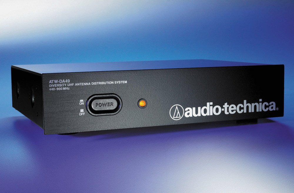
audio-technica ATW-DA49b UHF Antenna Distribution System
Introduction
Thank you for purchasing this Audio-Technica product. Before using the product, please read through this user manual when necessary, to ensure that you use the product correctly.
Safety precautions
Although this product was designed to be used safely, failing to use it correctly may result in an accident. To ensure safety, observe all warnings and cautions while using the product.
Important information
Warning: To prevent fire or shock hazard, do not expose this apparatus to rain or moisture.
Caution:
- Do not expose this apparatus to drips or splashes.
- To avoid electric shock, do not open the cabinet.
- Refer servicing to qualified personnel only.
- Do not expose this apparatus to excessive heat such as sunshine, fire or the like.
- Do not subject this apparatus to strong impact.
- This apparatus should be located close enough to the AC outlet so that you can easily grasp the AC adapter at any time.
- In case of emergency, disconnect the AC adapter quickly.
- Do not place any objects filled with liquids, such as vases, on this apparatus.
- To prevent fire, do not place any naked flame sources (such as lighted candles) on this apparatus.
- Do not install this apparatus in a confined space such as a bookcase or similar unit.
- Install this apparatus only in the place where ventilation is good.
Notes on use
- Be sure to read the connected device’s user manual before use.
- Turn off the power of the connected device before connecting or disconnecting cables.
- If you use the product near a TV or radio antenna, you may hear unwanted noise in the television or radio. If this occurs, move the product away from the device.
- The wireless system may be affected by electromagnetic noise from light dimmers, computers, OA devices, or electric musical instruments. Position the components of the system in a place where they are less likely to be affected.
- Only use the product in combination with devices specified by Audio-Technica.
Rack-mounting the product
- Screws for rack-mounting the product are not included.
- Consider ventilation when rack-mounting to avoid heat building up in the rack.
- When installing the product on a rack, make sure that the temperature inside the rack does not reach or exceed 45°C. Higher temperatures may negatively affect the internal parts of the product, causing the product to malfunction.
- Ensure at least a 10-millimeter space between the product and other devices or the top and side faces of the rack.
- Do not place any objects around the rear of this apparatus to ensure proper ventilation of this apparatus.
- The required rack specifications are as follows:
- EIA-standard 19-inch rack
- 1U-size attachable rack
- Rack with a shelf on which the product is placed or a guide rail that supports the product.
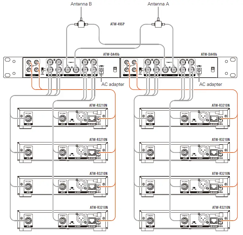
- Optional AT8631 joining plate allows two half-rack units to be mounted in a single 19″ rack space.
Maintenance
- If the product becomes dirty or covered with dust, be sure to turn off the connected device before wiping the product off with a dry and soft cloth.
- Do not use benzine, thinner or electrical contact cleaner, etc. They may deform or otherwise damage the product, or cause operational failure.
- When storing the product for an extended period, wrap the product in plastic to protect it from dust.
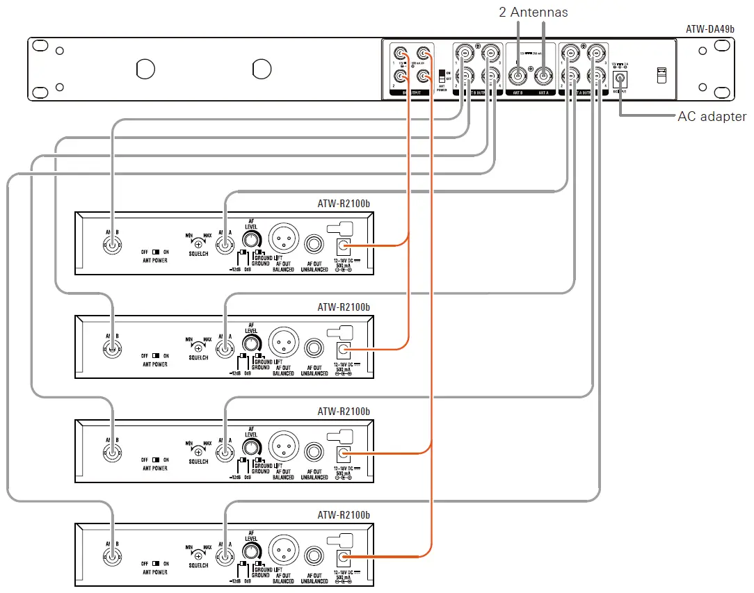
Making connections
Cautions when connecting
- Make sure to turn off the antenna power supply setting on the connecting wireless receiver. For setup methods, refer to the user manual of the wireless receiver.
- Before connecting an antenna, be absolutely sure to turn off the antenna power switch. When supplying power to an antenna, first connect the antenna and then turn on the antenna power switch.
- Confirm the frequency band of the connecting wireless receiver, antenna and accessories before use.
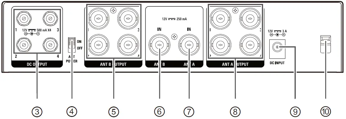
Part names and functions

- Power buttonPress to turn the power ON/OFF. An indicator lights up when the power is ON.
- Antenna power indicatorAn indicator lights up while 12V DC supplied to the antenna input jacks.
- DC Output jacksProvides 12V DC (center positive) at up to 500 mA from each jack to power receivers. Connect the included DC cables here to supply 12V DC to up to four receivers.
- Antenna power switchBy turning the antenna power switch ON.12V DC can be supplied to the antenna input jacks.
- Antenna B output jacksThese are four distribution output jacks of ATW-DA49b for Channel B.
- Antenna B input jackAttach the “B” antenna here. The antenna input jack also provides +12V DC output to power in-line RF devices.
- Antenna A input jackAttach the “A” antenna here. The antenna input jack also provides +12V DC output to power in-line RF devices.
- Antenna A output jacksThese are four distribution output jacks of ATW-DA49b for Channel A.
- Power input jackInput jack for the AC adapter.
- AC adapter cord hookHang the power cord of the AC adapter to prevent it from pulling loose accidentally.

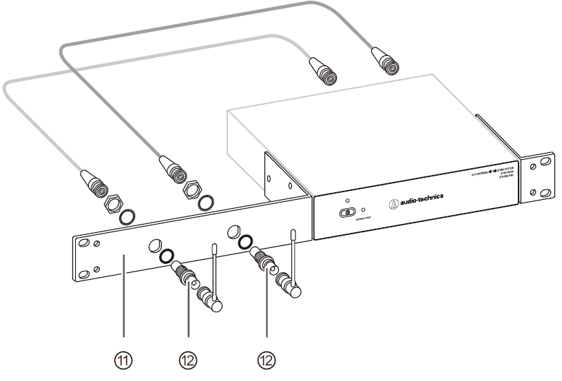
- Rack mount kitThe rack-mount hardware kit is provided to permit attachment in a standard 19″ equipment rack.
- BNC bulkhead connectors (optional)Antennas may be mounted on the front of the long rack ear.
Specifications
Frequency range 470 to 990 MHzInput/output 2 input, 2 × 4 distribution outputInput/output jack BNCOIP3 +35dBm (typ.)RF output gain +1.0 dB ± 2.0 dBInput/output gain +1.0 dB ± 2.0 dBAntenna input power supply 12 V DC, maximum 250 mA × 2Power supply 100 to 240 V AC (50/60 Hz) to 12V DC 3.0 A (center positive) switched mode external power supplyOperating temperature range -5°C to 45°C (23°F to 113°F)Dimensions 209 mm (8.23”)×43.5 mm (1.72”)×191 mm (7.52”) (W×H×D) (excluding protrusions)Weight 1.45 kg (3.2 lbs)Accessories Rack-mount kit (rack-mount × 2, mounting screw × 6), BNC cable × 10, DC power interconnect cables x 4, AC adapter and cord
For product improvement, the product is subject to modification without notice.
Audio-Technica Corporation2-46-1 Nishi-naruse, Machida, Tokyo 194-8666, Japanwww.audio-technica.com©2019 Audio-Technica CorporationGlobal Support Contact: www.at-globalsupport.com
![]()
References
[xyz-ips snippet=”download-snippet”]