
Audio-Technica ATDM-1012 / ATDM-1012DAN Quick Start Guide
ATDM-1012DIGITAL SMARTMIXER
ATDM-1012DANDIGITAL SMARTMIXER WITH DANTE
Important information
Warning:
To prevent fire or shock hazard, do not expose this apparatus to rain or moisture.
Caution:
- Do not expose this apparatus to drips or splashes.
- To avoid electric shock, do not open the cabinet.
- Refer servicing to qualified personnel only.
- Do not expose this apparatus to excessive heat such as that generated by sunshine, fire or other heat sources.
- Do not subject this apparatus to strong impact.
- This apparatus should be located close enough to the AC outlet so that you can easily grasp the power cord plug at any time. In case of emergency, disconnect the power cord plug of this apparatus quickly.
- Do not place any objects filled with liquids, such as vases, on this apparatus.
- To prevent fire, do not place any naked flame sources (such as lighted candles) on this apparatus.
- Do not install this apparatus in a confined space such as a bookcase or similar unit.
- Install this apparatus only in the places with good ventilation.
- To prevent fire, do not cover the ventilation of this apparatus with newspapers, table-clothes, curtains, etc.
- This apparatus with ClassⅠconstruction shall be connected to the AC outlet with a protective grounding connection.
Important Safety Instructions
- Read these instructions.
- Keep these instructions.
- Heed all warnings.
- Follow all instructions.
- Do not use this apparatus near water.
- Clean only with dry cloth.
- Do not block any of the ventilation openings. Install in accordance with the manufacturer’s instructions.
- Do not install near any heat sources such as radiators, heat registers, stoves, or other apparatus (including amplifiers) that produce heat.
- Do not defeat the safety purpose of the polarized or grounding plug. A polarized plug has two blades with one wider than the other. A grounding plug has two blades and a third grounding prong. The wide blade or the third prong is provided for your safety. If the provided plug does not fit into your outlet, consult an electrician for replacement of the obsolete outlet.
- 1Protect the power cord from being walked on or pinched particularly at plugs, convenience receptacles, and the point where they exit from the apparatus.
- Only use attachments/accessories specified by the manufacturer.
- Use only with a cart, stand, tripod, bracket, or table specified by the manufacturer, or sold with the apparatus. When a cart is used, use caution when moving the cart/apparatus combination to avoid injury from tip-over.
- Unplug this apparatus during lightning storms or when unused for long periods of time.
- Refer all servicing to qualified service personnel. Servicing is required when the apparatus has been damaged in any way, such as power-supply cord or plug is damaged, liquid has been spilled or objects have fallen into the apparatus, the apparatus has been exposed to rain or moisture, does not operate normally, or has been dropped.
For customers in the USA/Canada

FCC Notice
Warning:This device complies with Part 15 of the FCC Rules. Operation is subject to the following two conditions: (1) This device may not cause harmful interference, and (2) this device must accept any interference received, including interference that may cause undesired operation.
Caution:You are cautioned that any changes or modifications not expressly approved in this manual could void your authority to operate this equipment.
Note:This equipment has been tested and found to comply with the limits for a Class B digital device, pursuant to part 15 of the FCC Rules. These limits are designed to provide reasonable protection against harmful interference in a residential installation. This equipment generates, uses and can radiate radio frequency energy and, if not installed and used in accordance with the instructions, may cause harmful interference to radio communications. However, there is no guarantee that interference will not occur in a particular installation. If this equipment does cause harmful interference to radio or television reception, which can be determined by turning the equipment off and on, the user is encouraged to try to correct the interference by one or more of the following measures:
- Reorient or relocate the receiving antenna.
- Increase the separation between the equipment and receiver.
- Connect the equipment into an outlet on a circuit different from that to which the receiver is connected.
- Consult the dealer or an experienced radio/TV technician for help.
Contact:Responsible Company: Audio-Technica U.S., Inc.Address: 1221 Commerce Drive, Stow, Ohio 44224, USATel: 330-686-2600
For customers in Canada
IC statementCAN ICES-3 (B)/NMB-3 (B)
Notes on use
- When using the product, also read the user manuals supplied with the devices that are to be connected.
- When not using the product, remove the power plug from the power outlet.
- Turn the product off before connecting or disconnecting cables.
- If you use the product near a TV or radio antenna, noise may be generated in the TV or radio. In this case, move the product away from the TV or radio antenna.
Operating the front/rear panel (Figure 1)
- Front
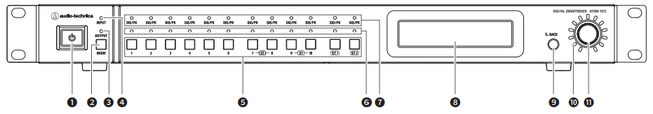
- Power button
- MODE button
- OUTPUT LED
- INPUT LED
- Channel select button
- Channel select LED
- SIG/PK LED
- Display
- BACK button
- Volume LED
- Dial button
- Rear

- NETWORK terminal DANTE/network terminal (ATDM-1012DAN)
- USB terminal
- Audio-Technica LINK A/B/C/D terminal
- Unbalanced output terminal (ST1, ST2)
- Balanced output terminal (1 to 8)
- Unbalanced input terminal (ST1, ST2)
- Balanced input terminal (1 to 10)
- Ground screw
- AC inlet
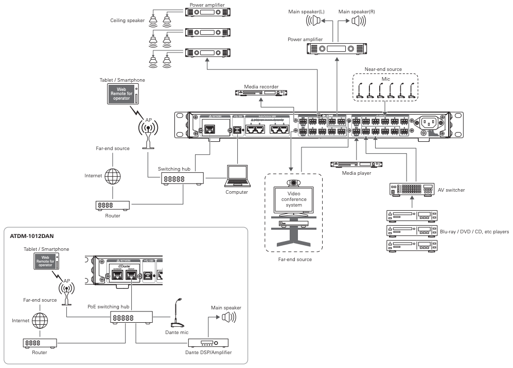
System Connection example (Figure 2)
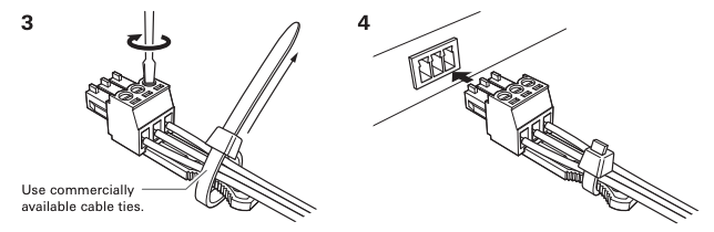
- Connecting Euroblock connectors

Operating the display panel (Figure 3)
- Front panel mode
- Function menu
- IP config mode (Auto/Static)
Information about the Quick Start Guide (this document)
This document provides typical connection examples and explains how to use a web browser or mobile device to configure the system. For details about connections and operations, refer to the user manual available for download on our website.
Trademarks
- SMARTMIXER™ is a trademark or registered trademark of Audio-Technica Corporation.
- Apple and the Apple logo are trademarks of Apple Inc., registered in the U.S. and other countries.
- iOS is a trademark or registered trademark of Cisco in the U.S. and other countries.
- App Store is a service mark of Apple Inc.
- Google, the Google logo, Google Play, the Google Play logo, and Android™ are trademarks or registered trademarks of Google Inc.
- All other company and product names that appear in this document are trademarks or registered trademarks of their respective owners.
Package contents
- ATDM-1012/ATDM-1012DAN unit
- Euroblock connectors ×22
- Power cable
- Quick Start Guide (this document)
Downloading the user manual and application
- User manual
Download from the Audio-Technica website for your country or region.www.audio-technica.com
- “Locate” launcher application, used for Web Remote control
For Windows and Mac:Download from the Audio-Technica website for your country or region.www.audio-technica.com
Operating the front panel
Refer to Figure 3 when reading this section.
- Starting the product
- Press the power button.
- The product starts in administrator mode as the default.
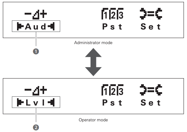
- Changing the front panel mode (operator mode/administrator mode)
- While pressing the MODE button, press and hold the dial button for 1 or more seconds.
- The front panel mode changes each time pressing the buttons.
| Operator mode | Administrator mode |
| Displays “Lvl” (❷). | Displays “Aud” (❶). |
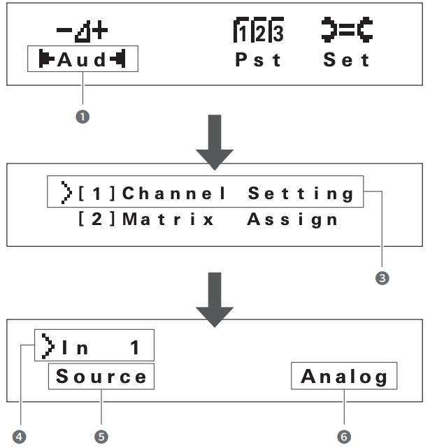
- Selecting each function
- Turn the dial button on the home screen, select “Aud” (❶), and press the dial button.
- Turn the dial button, select “Channel Setting” (❸), and press the dial button.
- Turn the dial button to select the channel (❹) you want to adjust.
- Press the MODE button to switch the INPUT/OUTPUT channel.– INPUT LED ON: INPUT channel– INPUT LED blinking: SUB INPUT channel– OUTPUT LED ON: OUTPUT channel
- Press the dial button.
- The cursor moves.
- Turn the dial button to select the function (❺).
- Press the dial button to set the parameters (❻) of each function.
- Selectable functions are shown as follows. (Some functions may not be displayed depending on the setting. For details, refer to the user manual.)
| 1. Source | 9. Comp Insertion |
| 2. Unity | 10. Compressor |
| 3. Gain | 11. Smart Mix |
| 4. Phantom | 12. Priority |
| 5. Phase | 13. AEC |
| 6. Low Cut | 14. Level |
| 7. FBS | 15. Mute |
| 8. EQ | 16. Limitter |
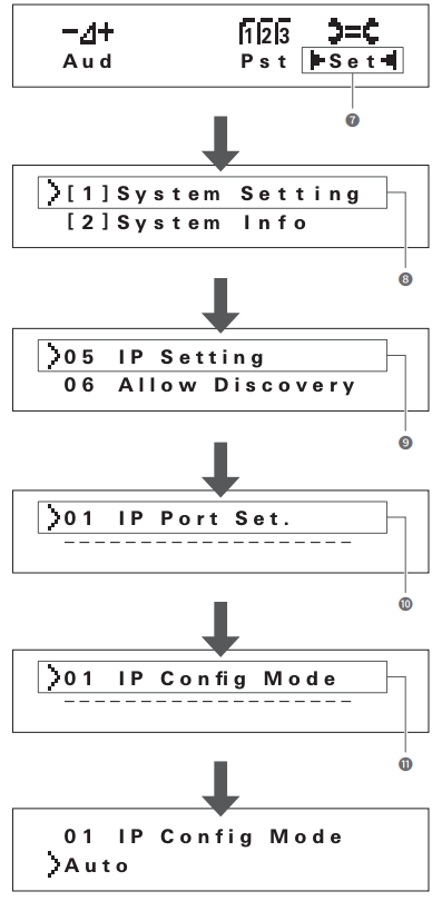
- Changing the IP config mode (Auto/Static)
- Turn the dial button on the home screen, select “Set” (❼), and press the dial button.
- Turn the dial button to select “System Setting” (❽) and press the dial button.
- Turn the dial button to select “IP Setting” (❾) and press the dial button.
- Turn the dial button to select “IP Port Set.” (❿) and press the dial button.
- Turn the dial button to select “IP Config Mode” (⓫) and press the dial button.
- Turn the dial button to select “Auto”/”Static” and press the dial button.
- Press the power button to restart the product.
Web Remote
- Connecting a control device
- A Windows computer, Mac, iOS device, or Android device used for controlling the product via Web Remote is called a control device.
- For details about connecting a control device, refer to the user manual.
- Before connecting a control device to the product, network settings for both devices must be performed.
- If IP addresses are obtained automatically when connecting
- Set the product’s IP config mode to “Auto”.– The product ships from the factory in “Auto” mode.
- Set the control device’s network settings, so that it connects to the network.
- If static IP addresses are used when connecting
- Set the product’s IP config mode to “Static”.– The IP address is set to a static value. The default value is “192.168.33.102”.– For details, refer to the user manual.
- If IP addresses are obtained automatically when connecting
- Use a wired or wireless connection to connect the control device to the product.
- Turn on the control device and the product.
- If IP addresses are obtained automatically when connecting, it may take some time before the IP address is set.
- Starting Web Remote
Using the “Locate” application to launch the Web Remote
- Use a control device that has “Locate” installed on it, and start “Locate”.
- For details about installation, refer to the user manual.
- From the list, select the product to start Web Remote.
Specifying an IP address to launch the Web Remote
If the IP address of the product is known, it is possible to access it and launch the Web Remote directly.
- Open the control device’s web browser.
- In the web browser, enter the IP address of the product to start Web Remote.
References
[xyz-ips snippet=”download-snippet”]