

User Manual
Flush-mount Microphone Socket with LED Ring and Touch Switch AT8657/LED-Saudio-Technica
Thank you for purchasing this product. Before using the product, read through the user manual to ensure that you will use the product correctly. Please keep this manual for future reference.
Features
- Flush-mount microphone socket for the AT846C / AT846O or any phantom-powered gooseneck microphone with a 3-pin XLRM-type output and a base diameter no greater than 21 mm
- Mounts unobtrusively in tabletops
- Switch logic output permits control of remote devices from built-in capacitance switch
- Integral, phantom-powered, Green/Red LED indicator ring
- Operates on 24-48V DC phantom power
- 3-pin XLRF-type connector for the microphone, 5-pin XLRM-type connector for output
- Lock tab in socket case automatically locks microphone in place, holding it there until tab is manually released by the user
- Isolators provide mechanical dampening of mounting-surface vibration
- Low-profile design with low-reflectance black finish for minimum visibility
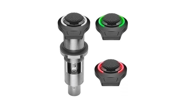
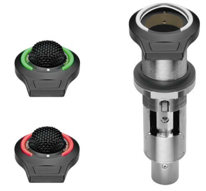
Description
The AT8657/LED-S flush-mount microphone socket features a capacitive-type touch-sensitive switch, Red/Green LED indicator ring, a switch logic output for controlling remote devices, and a lock tab to hold the microphone in place. The socket is equipped with a three-pin XLRF-type in, and a five-pin XLRM-type output connector.The AT8657/LED-S requires 24-48V DC phantom power for operation. The electronics in the socket take up to 30 seconds to stabilize after power is applied; during this start-up period, some sonic disturbances may be heard upon switching if the system is “live.”The touch-sensitive switch can be used to trigger an external device.The lock tab, located in the socket case, automatically engages when the microphone is inserted, securely holding it in place until tab is manually released by the user.The output of the socket is a 5-pin XLRM-type connector.Isolators are included with the unit for mechanical isolation from the mounting surface. A retaining ring is also included for use with gooseneck microphones. The socket is enclosed in a heavy-duty die-cast case. The low-profile housing has a low-reflectance black finish.
Connection procedure
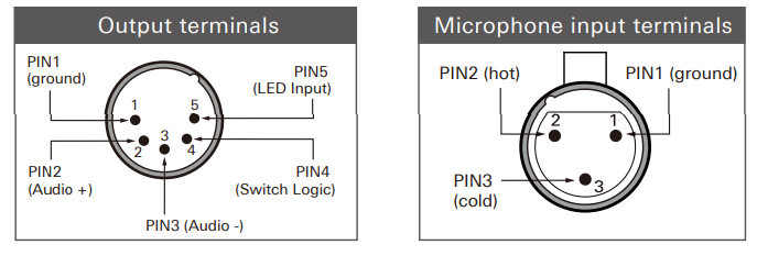
Connect the output terminals of AT8657/LED-S to a device that has a microphone input (balanced input) compatible with a phantom power supply, a switch logic control output, and a LED logic input. The input/output connectors are XLRM-type with polarity as shown in the figure below.
AT8657/LED-S requires 24-48 V DC phantom power.
Specifications
| Output impedance | 360 Ohms |
| Switch logic | High (+5V DC) when pressed;Low (0V DC) when not pressed |
| I/O voltage | -0.5V to 5.5V |
| LED input | Red when high (+5V DC), Green when low (0V DC), |
| Maximum input voltage | -0.5V to 5.5V |
| Phantom power requirements | 24-48V DC, 4 mA typical |
| Switch | Touch-sensitive control : momentary |
| Weight | 165 g |
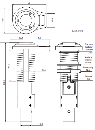
| Dimensions | 130.6 mm long, 55.0 mm maximum width |
| Intput connector | 3-pin XLRF-type |
| Output connector | 5-pin XLRM-type |
| Accessories furnished | One pair isolators, one set metal retainer ring |
Installation and Operation
The AT8657/LED-S requires 24-48V DC phantom power for operation.Output is low impedance (Lo-Z) balanced. The signal appears across Pins 2 and 3; Pin 1 is ground (shield). The output phase is “Pin 2 hot” – positive acoustic pressure produces positive voltage at Pin 2. Switch logic output appears between pins 1 and 4. LED logic input appears between pins 1 and 5. The microphone socket should be installed on a flat, unobstructed mounting surface.The AT8657/LED-S should be mounted to a tabletop using the included isolators in order to dampen surface vibration. To mount the socket with the isolators, a 35 mm hole is recommended. Place the isolators on either side of the hole to achieve mechanical isolation from the mounting surface.The AT8657/LED-S’s capacitive-type touch-sensitive switch allows the user to trigger a function on an external device: Switch logic output is High (+5V DC) when pressed.Low (0V DC) when not pressed.The LED indicator ring lights red when logic high (+5V DC) and green when logic low (0V DC).
Dimensions
Audio-Technica Corporation2-46-1 Nishi-Naruse, Machida, Tokyo 194-8666, Japan©2017 Audio-Technica CorporationGlobal Support Contact: www.at-globalsupport.com
References
[xyz-ips snippet=”download-snippet”]