Warning: Use of undefined constant id – assumed ‘id’ (this will throw an Error in a future version of PHP) in /home/admin/domains/manualsplanet.com/public_html/praca/dom_delete_new.php on line 17
Warning: Use of undefined constant id – assumed ‘id’ (this will throw an Error in a future version of PHP) in /home/admin/domains/manualsplanet.com/public_html/praca/dom_delete_new.php on line 18
Warning: Use of undefined constant id – assumed ‘id’ (this will throw an Error in a future version of PHP) in /home/admin/domains/manualsplanet.com/public_html/praca/dom_delete_new.php on line 18
Warning: Creating default object from empty value in /home/admin/domains/manualsplanet.com/public_html/praca/dom_delete_new.php on line 212
Warning: Creating default object from empty value in /home/admin/domains/manualsplanet.com/public_html/praca/dom_delete_new.php on line 138
audio-technica Microline Condenser User Manual
■ Introduction
Thank you for purchasing this product. Before using the product, read through the user manual to ensure that you will use the product correctly. Please keepthis manual for future reference.
■ Features
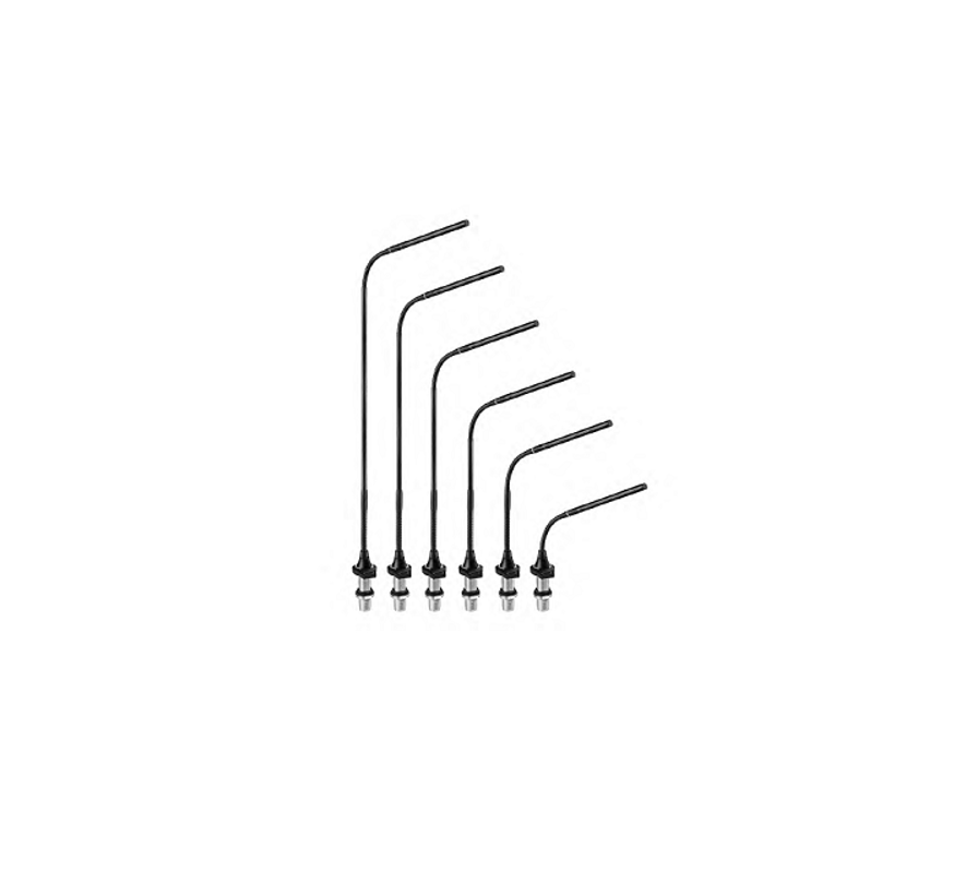
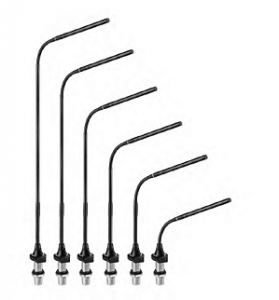
- Modular microphone system comprised of an ES Series capsule, gooseneck assembly, and power module.
- RGB LEDs built into both the flush-mount power module and gooseneck assembly indicate the on/off status of the microphone.
- Includes external control function for device control from the capacitive touch switch.
■ Safety precautions
Although this product was designed to be used safely, failing to use it correctly may result in an accident. To ensure safety, observe all warnings and cautionswhile using the product.
■ Cautions for the product
- Do not subject the product to strong impact to avoid malfunction.
- Do not disassemble, modify or attempt to repair the product.
- Do not handle the product with wet hands to avoid electric shock or injury.
- Do not store the product under direct sunlight, near heating devices or in a hot, humid or dusty place.
■ Notes on use
- Check the strength of the mounting area. Insufficient strength or poor mounting will cause objects to fall or become damaged.
- The circuitry in the microphone takes about 30 seconds to stabilize after power is supplied. You may hear some audio disturbance during startup.
- Install the microphone on a flat, unobstructed mounting surface.
- Depending on the surface finish of a table, the isolators may leave marks on the table.
- Do not excessively bend the gooseneck assembly, rotate the ends of the capsule, or pull on them. Doing so may cause disconnection or malfunction.
- The product is a modular system comprised of a microphone element, gooseneck assembly and power module. Make sure the parts are firmly attached before use.
- Do not remove the rubber O-ring on the power module connecting part at the lower section of the gooseneck assembly.
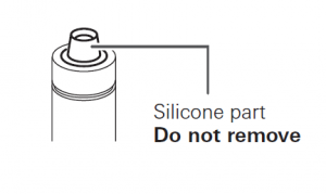
- When attaching parts, remove the black cap on the capsule connecting part of the gooseneck assembly. Do not remove the silicone part at the end of the capsule connecting part.
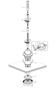
■ Assembly
- Insert the gooseneck assembly (c) while rotating it into the flush-mount power module (d).
- Tighten until it does not rotate, and use the hex wrench (i) to tighten the set screw (h) and set the gooseneck assembly in place.
- Connect the capsule (b) to the gooseneck assembly, and attach the windscreen (a).
- If the parts are not sufficiently tightened together, problems may occur such as the LED colors of the gooseneck assembly and power module not matching or sound is not output.
- Refer to the LED table to the right and set the LED color before attaching to the mounting surface.
- If you are installing the flush-mount power module on a table without the isolators, you must make a hole with a diameter of 20.5 mm in the mounting surface.
- If you are installing with the isolators, the hole must have a diameter of 23.5 mm. Inserting the isolators between the mounting surface and power module allows you to separate the flush-mount power module from the mounting surface.
- Attach the upper part isolator (e) to the mounting surface, and attach the flushmount power module (d). Attach the lower isolator (f) to the reverse side of the mounting surface, and then tighten the nut (g).
■ Switch setting and functions

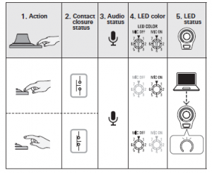
■ LED color

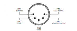
■ Wiring
■ Specifications
ES925MLx/FM5
| Element | Fixed-charge back plate, permanently polarized condenser |
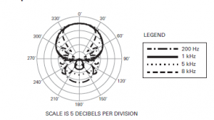
| Polar pattern | Line + Gradient |
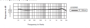
| Frequency response | 30 – 20,000 Hz |
| Open circuit sensitivity | -35dB (17.7mV) (0dB=1V/Pa, 1kHz) |
| Impedance | 130 ohms |
| Maximum input sound level | 137 dB SPL (1kHz at 1% THD) |
| Dynamic range | 114 dB (1kHz at Max SPL) |
| Signal-to-noise ratio | 71 dB (1kHz at 1Pa, A-weighted) |
| Phantom powerrequirements | 22 – 52 V DC, 7.6 mA |
| Contact closureClosure input voltageMaximum permissible powerOn-resistance | -0.5 – 5.5 V200 mW100 ohms |
| LED controlActive low voltageMaximum permissibleinput powerMaximum permissiblepower | Active high (+5 V DC) TTL compatible1.2 V or lower-0.5 – 5.5 V200 mW |
| Weight | ES925ML6/FM5: 114.2 g (4.0 oz)ES925ML12/FM5: 138.2 g (4.9 oz)ES925ML15/FM5: 143.2 g (5.1 oz)ES925ML18/FM5: 148.2 g (5.2 oz)ES925ML21/FM5: 153.2 g (5.4 oz)ES925ML24/FM5: 158.2 g (5.6 oz) |
| Dimensions | ES925ML6/FM5: 326.5 mm (12.9“) x 38 mm (1.5“) x 48 mm (1.9“)ES925ML12/FM5: 434 mm (17.1“) x 38 mm (1.5“) x 48 mm (1.9“)ES925ML15/FM5: 510.2 mm (20.1“) x 38 mm (1.5“) x 48 mm (1.9“)ES925ML18/FM5: 586.4 mm (23.1“) x 38 mm (1.5“) x 48 mm (1.9“)ES925ML21/FM5: 662.6 mm (26.1“) x 38 mm (1.5“) x 48 mm (1.9“)ES925ML24/FM5: 738.8 mm (29.1“) x 38 mm (1.5“) x 48 mm (1.9“)(H×W×D) |
| Output connector | 5-Pin XLRM-type |
| Optional interchangeableelements | ESE-Ca (120°), ESE-Ha (100°), ESE-Oa (360°) |
| Included accessories | Isolator 1 pair, Nut, Windscreen AT8138a,Set screw (M2×2 mm (0.08“)) 2 pcs., Hex wrench (M2) |
■ Polar pattern
■ Frequency response
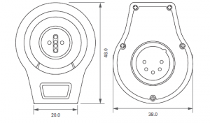
■ Dimensions

Audio-Technica Corporation2-46-1 Nishi-naruse, Machida, Tokyo 194-8666, Japan©2020 Audio-Technica CorporationGlobal Support Contact: www.at-globalsupport.comMade in Japan
Read More About This Manual & Download PDF:
[xyz-ips snippet=”download-snippet”]