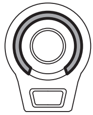
audio-technica Modular Gooseneck Microphone with 3-Pin Flush-Mount Power
Thank you for purchasing this product. Before using the product, read through the user manual to ensure that you will use the product correctly. Please keep this manual for future reference.
ES925
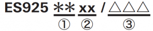
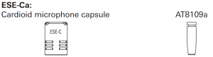
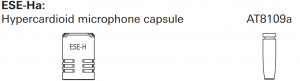
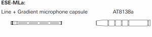
| ① Microphone Capsule |
C |
 |
|
H |
 |
|
|
ML |
 |
|
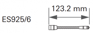
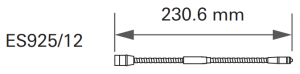
| ② Gooseneck Assembly |
6 |
 |
|
12 |
 |
|
|
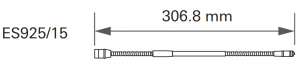
15 |
 |
|
|
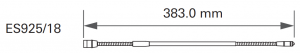
18 |
 |
|
|
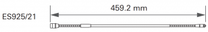
21 |
 |
|
|
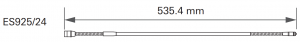
24 |
 |
|
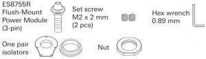
| ③ Power Module & Accessories |
FM3 |
 |
Safety precautions
Although this product was designed to be used safely, failing to use it correctly may result in an accident. To ensure safety, observe all warnings and cautions while using the product.
Cautions for the product
- Do not subject the product to strong impact to avoid malfunction.
- Do not disassemble, modify or attempt to repair the product.
- Do not handle the product with wet hands to avoid electric shock or injury.
- Do not store the product under direct sunlight, near heating devices or in a hot, humid or dusty place.
Notes on use
- Check the strength of the mounting area. Insufficient strength or poor mounting will cause objects to fall or become damaged.
- The circuitry in the microphone takes about 30 seconds to stabilize after power is supplied. You may hear some audio disturbance during startup.
- Install the microphone on a flat, unobstructed mounting surface.
- Depending on the surface finish of a table, the isolators may leave marks on the table.
- Do not excessively bend the gooseneck assembly, rotate the ends of the capsule, or pull on them. Doing so may cause disconnection or malfunction.
- The product is a modular system comprised of a microphone element, gooseneck assembly and power module. Make sure the parts are firmly attached before use.
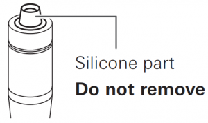
- Do not remove the rubber O-ring on the power module connecting part at the lower section of the gooseneck assembly.
- When attaching parts, remove the black cap on the capsule connecting part of the gooseneck assembly. Do not remove the silicone part at the end of the capsule connecting part.

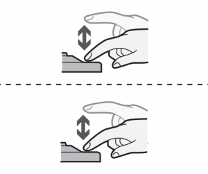
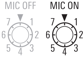
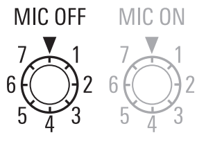
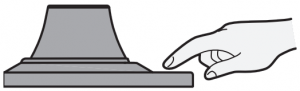
Switch setting and functions
| 1. Action
|
2. Audio status
|
3. LED color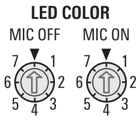 |
4. LED status
|
 |
 |
 |
|
 |
 |
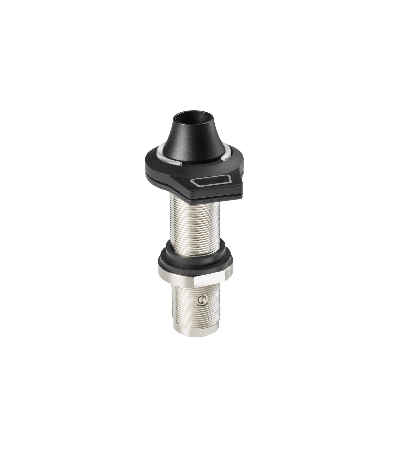
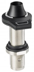
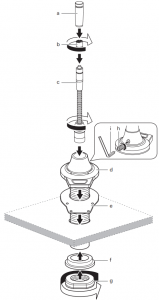
Assembly
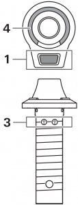
- Insert the gooseneck assembly (c) while rotating it into the flush-mount power module (d), and tighten it firmly. Check that the gooseneck assembly does not rotate, and use the included hex wrench (i) to tighten the set screw (h). Connect the capsule (b) to the gooseneck assembly, and attach the windscreen (a). If the parts are not sufficiently tightened together, problems may occur such as the LED colors of the gooseneck assembly and power module not matching or sound is not output.
- Refer to the LED table to the right and set the LED color before attaching to the mounting surface.
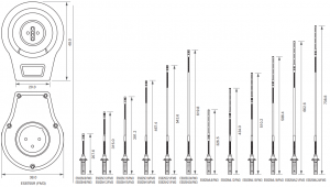
- If you are installing the flush-mount power module on a table without the isolators, you must make a hole with a diameter of 20.5 mm in the mounting surface. If you are installing with the isolators, the hole must have a diameter of 23.5 mm. Inserting the isolators between the mounting surface and power module allows you to separate the flush-mount power module from the mounting surface.
- Attach the upper part isolator (e) to the mounting surface, and attach the flush-mount power module (d). Attach the lower isolator (f) to the reverse side of the mounting surface, and then tighten the nut (g).
Dimensions
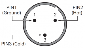
Wiring
LED / LED color
|
▼ |
1 |
2 | 3 | 4 | 5 | 6 |
7 |
|
OFF |
RED | GREEN | YELLOW | BLUE | MAGENTA | CYAN |
WHITE |
Warranty (Please be sure to read the notes below.) For USA Only
End-User LIMITED WARRANTY information for the USA is available at www.audio-technica.com/usawarranties. You may also contact Audio-Technica U.S., Inc. to request a written copy of the Limited Warranty at 1-330-686-2600 or via mail at 1221 Commerce Drive, Stow, OH 44224.
Audio-Technica Corporation
2-46-1 Nishi-naruse, Machida, Tokyo 194-8666, Japan©2019 Audio-Technica CorporationGlobal Support Contact: www.at-globalsupport.com
[xyz-ips snippet=”download-snippet”]