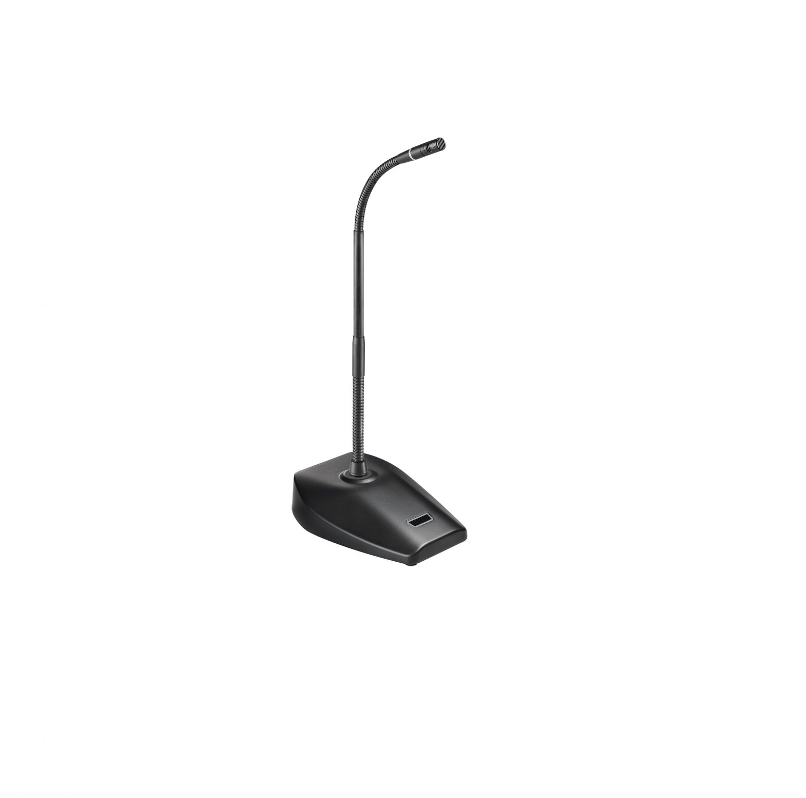
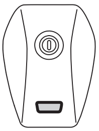
audio-technica Modular Gooseneck Microphone with 5-Pin Desk Stand Power
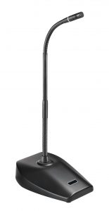
ES925
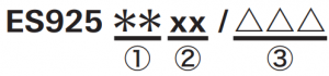
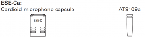
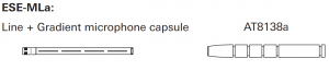
| ① Microphone Capsule |
C |
 |
|
H |
|
|
|
ML |
 |
|
| ② Gooseneck Assembly |
6 |
 |
|
12 |
 |
|
|
15 |
 |
|
|
18 |
|
|
|
21 |
 |
|
|
24 |
 |
|
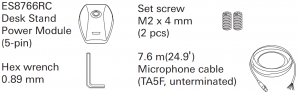
| ③ Power Module & Accessories |
DS5 |
 |
Thank you for purchasing this product. Before using the product, read through the user manual to ensure that you will use the product correctly. Please keep this manual for future reference.
Safety precautions
Although this product was designed to be used safely, failing to use it correctly may result in an accident. To ensure safety, observe all warnings and cautions while using the product.
Cautions for the product
- Do not subject the product to strong impact to avoid malfunction.
- Do not disassemble, modify or attempt to repair the product.
- Do not handle the product with wet hands to avoid electric shock or injury.
- Do not store the product under direct sunlight, near heating devices or in a hot, humid or dusty place.
Notes on use
- Do not swing or pull the product. Doing so may cause disconnection or damage.
- The circuitry in the microphone takes about 30 seconds to stabilize after power is supplied. You may hear some audio disturbance during startup.
- The connectors are equipped with a special RFI shielding mechanism. If you remove or replace the connector, you may adversely affect the microphone’s RFI immunity. The Audio-Technica Crimp Tool (ATCT) and shield parts are required to shorten the cable and reinstall the connector while maintaining the RFI immunity.
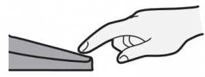
- Install the microphone on a flat, unobstructed mounting surface. Make sure that the sound source is not below the mounting surface.
- Depending on the surface finish of a table, the desk stand power module may leave marks on the table.
- Do not excessively bend the gooseneck assembly, rotate the ends of the capsule, or pull on them. Doing so may cause disconnection or malfunction.
- The product is a modular system comprised of a microphone element, gooseneck assembly and power module. Make sure the parts are firmly attached before use.
- Do not remove the rubber O-ring on the power module connecting part at the lower section of the gooseneck assembly.
- When attaching parts, remove the black cap on the capsule connecting part of the gooseneck assembly. Do not remove the silicone part at the end of the capsule connecting part.


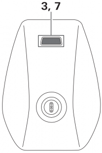
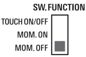
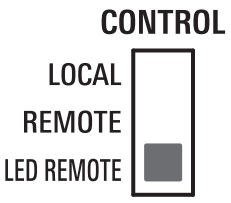
Switch setting
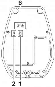
- To reduce low-frequency ambient noise (such as footsteps or air conditioning noise), room reverberation, and mechanically coupled vibrations as much as possible, turn on the low-cut filter switch () on the bottom of the power module.
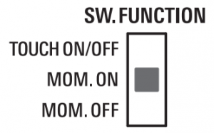
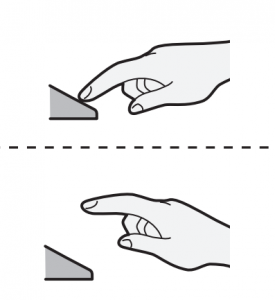
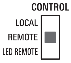
Switch setting and functions
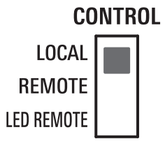
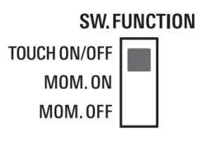
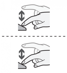
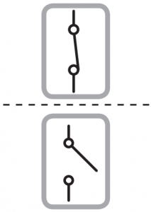
| 1. Control | 2. Switch Function | 3. Action
|
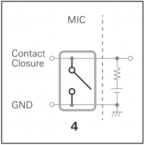
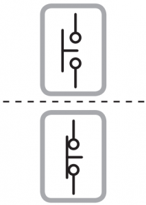
4. Contact closure status | 5. Audio status
|
6. LED color
|
7. LED status
|
 |
 |
 |
 |
 |
||
 |
||||||
 |
 |
 |
|
|||
|
||||||
 |
|
 |
|
|||
|
||||||
 |
|
|
|
|
||
|
||||||
|
|
|
|
|||
|
||||||
|
|
|
|
|||
|
||||||
 |
|
|
|
|
 |
|
|
|
|
||||
|
|
|
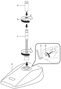
Assembly
- Insert the gooseneck assembly (c) while rotating it into the desk stand power module (d), and tighten it firmly. Check that the gooseneck assembly does not rotate, and use the included hex wrench (h) to tighten the set screw (g). Connect the capsule (b) to the gooseneck assembly, and attach the windscreen (a). If the parts are not sufficiently tightened together, problems may occur such as the LED colors of the gooseneck assembly and power module not matching or sound is not output.
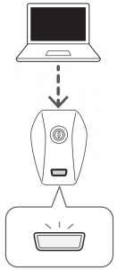
- Connect the included cable to the connector (e) on the reverse side of the desk stand power module, and pass the cable through the wire slot (f).
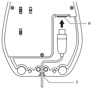
Wiring

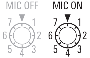
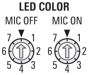
LED / LED color
|
▼ |
1 |
2 | 3 | 4 | 5 | 6 |
7 |
|
OFF |
RED | GREEN | YELLOW | BLUE | MAGENTA | CYAN |
WHITE |
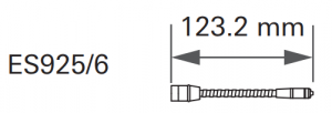
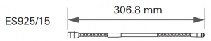
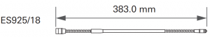
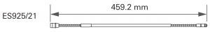
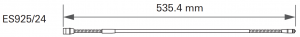
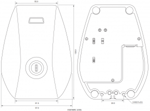
Dimensions

Audio-Technica Corporation
2-46-1 Nishi-naruse, Machida, Tokyo 194-8666, Japan©2019 Audio-Technica CorporationGlobal Support Contact: www.at-globalsupport.com
[xyz-ips snippet=”download-snippet”]