![]()
Quick GuideFor EVO II Series![]()
WELCOME TO EVO II
Now you can explore, discover and create like never before. The EVO II delivers not only advanced features like obstacle avoidance and intelligent flight modes but also a high-tech muscle that brings home a top speed of 44mph, 35-minute flight hover time, 40-minute flight time, and an operating distance of 5.6 miles.
In-flight performance, however, is just the start. The EVO II’s stabilized 3-axis camera allows you to shoot at up to 8K/25 fps, and view the live feed at up to 1080p on your mobile device or the remote control’s built-in OLED screen.Welcome to the Autel Robotics family. Use this guide to get an overview of EVO II’s features and how to use them.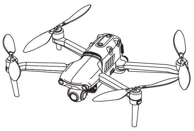
![]() IMPORTANT:Consult all reviewable documentation before your first flight. Failure to operate the aircraft responsibly could lead to injury or damages and may void any applicable warranty coverage
IMPORTANT:Consult all reviewable documentation before your first flight. Failure to operate the aircraft responsibly could lead to injury or damages and may void any applicable warranty coverage
AIRCRAFT FRONT & REAR & LEFT VIEWS
| 1. Propellers | 2. Landing Gear | 3. Motors |
| 4. Forward Vision System | 5. Front LED Indicators | 6. Camera Gimbal |
| 7. Power Button | 8. Rear LED Indicators | 9. Rear Vision System |
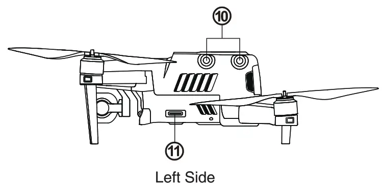
| 10. Left Vision System | 11. SD Card Port |
AIRCRAFT RIGHT & TOP & BOTTOM VIEWS
| 12. Right Vision System | 13. Aircraft Battery |
| 14. Fan Exhaust | 15. USB Port |
| 16. Remote Control Pairing Button/Pairing Indicator |
| 17. Top Vision System |
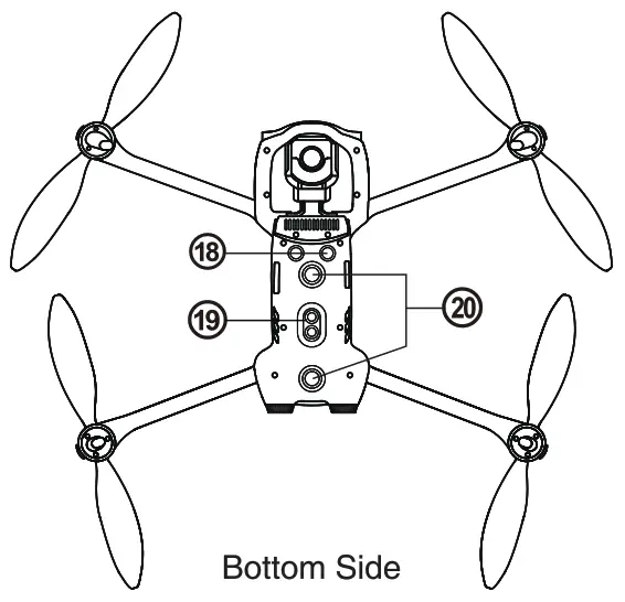
| 18. Ultrasonic Sensor | 19. Downward Vision Lighting LED | 20. Downward Vision System |
FLIGHT LED INDICATIONS
A LED indicator is located on the end of each aircraft arm. The front LEDs will light up solid red to help you identify the direction of the aircraft’s nose. The rear LEDs will display the current flight status of the aircraft. The chart below shows the meaning of each status indicator.
Color Key:R — Red ColorY — Yellow ColorG — Green ColorIndicator Key:Slow Flashing: Flashes once every 2sFast Flashing: Flashes twice per secondDouble Flashing: Flashes twice and then pauses and repeatsAlternate Flashing: Alternates among different colors
Example: “R – Solid Light” means solid red light.
|
Definitions of Flight LED Indicator Status |
|
|
Normal Status |
|
| RGY – Alternate Flashing | System self-test is activated |
| YG – Alternate Flashing | The aircraft is warming up |
| G – Slow Flashing | The aircraft is in GPS mode |
|
Warning |
|
| Y – Slow Flashing | The aircraft is in ATTI mode |
| Y – Fast Flashing | No connection between the aircraft and remote control |
| R – Slow Flashing | Low Battery Warning |
| R – Fast Flashing | Critically Low Battery Warning |
| R – Solid Light | Critical problems, IMU error |
| RY – Alternate Flashing | Abnormal com ass calibration is required Magnetometer inte erence |
|
Compass Calibration |
|
| Y – Fast Flashing | Be read to calibrate the compass / The aircraft is calibrating |
| G – Solid Light | Calibration is successful |
| R – Solid Light | Calibration is failed |
|
Gesture Commands |
|
| R – Fast Flashing | Gesture command has been received |
ROMOTE CONTROL
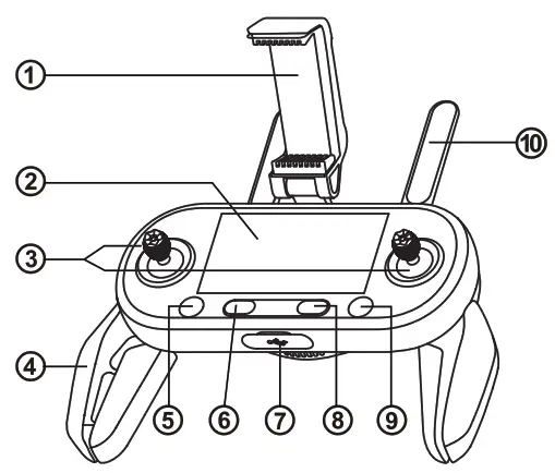
| 1. Mobile Device Holder | With a 180° adjustable viewing angle for optimum visibility |
| 2. Flight Information Panel | Displays the flight status, warning messages and live video feed |
| 3. Command Sticks | Control the orientation and movement of the aircraft |
| 4. Hand Grips | Foldable to allow for compact storage |
| 5. Take-off/Landing Button | Commands the aircraft to take off or land |
| 6. Power Button | Press and hold the button for 2 seconds to turn on/off the remote control |
| 7. USB Ports | Used for charging or connecting to a mobile device |
| 8. Pause Button | Tells the aircraft to pause autonomous flight operations and hover in place, or resume autonomous flight operations. |
| 9. Go Home Button | Commands the aircraft to return to the home point |
| 10. Antennas | Communicate with the aircraft at 2.4 GHz |
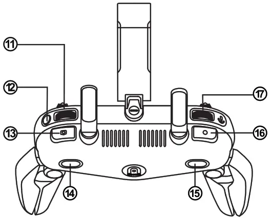
| 11. Screen Navigation Dial | Scrolls around the OLED screen |
| 12. Screen Navigation Button | When the mobile device is disconnected, press this button for 1 second to enter e it the Image Transmission screen on the remote control |
| 13. Shutter Button | Takes photos. When Burst Mode is turned on, several images will be taken with one press. For details, see the App Manual. |
| 14. Button A | Function can be set using the Autel Explorer™ app |
| 15. Button B | Function can be set using the Autel Explorer™ app |
| 16. Record Button | Starts or stops recording video |
| 17. Gimbal Pitch Dial | Controls the pitch angle of the camera gimbal |
CHARGING THE AIRCRAFT & REMOTE CONTROL
The aircraft battery and remote control can be charged simultaneously using the supplied charger.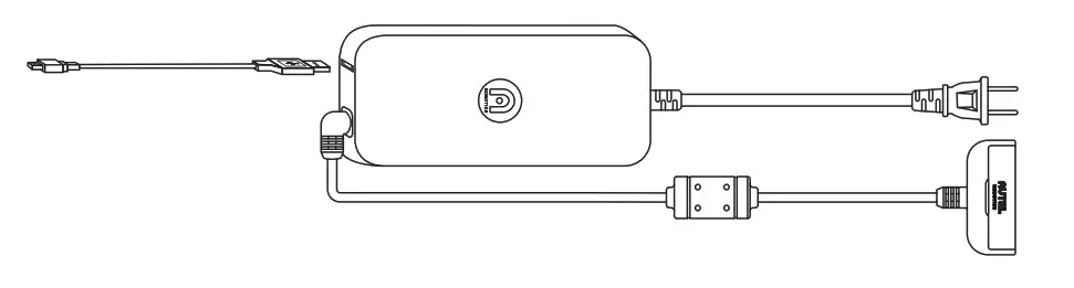
- Aircraft Battery: Plug the charging connector into the battery’s charge port.

- Remote Control: Open the protector on the USB port and plug in the provided charging cable.
NOTE
- Always fully charge the aircraft and remote control battery before flying.
- It takes approximately 90 minutes to fully charge the aircraft battery, and 180 minutes to charge the remote control.
INSTALLING THE AUTEL EXPLORERTM APP(OPTIONAL)
The Autel Explorer™ app delivers a live stream, and enhanced flight and camera controls to your mobile device. Follow the steps below to get connected.
- Search for ‘Autel Explorer’ from the App Store or Google Play and install the app for EVO II on your mobile device.
- Launch the app on your mobile device.
- Connect the mobile device to the remote control by following the onscreen prompts.

NOTE: Autel Explorer supports iOS 9.0 or later and Android 4.4 or later.
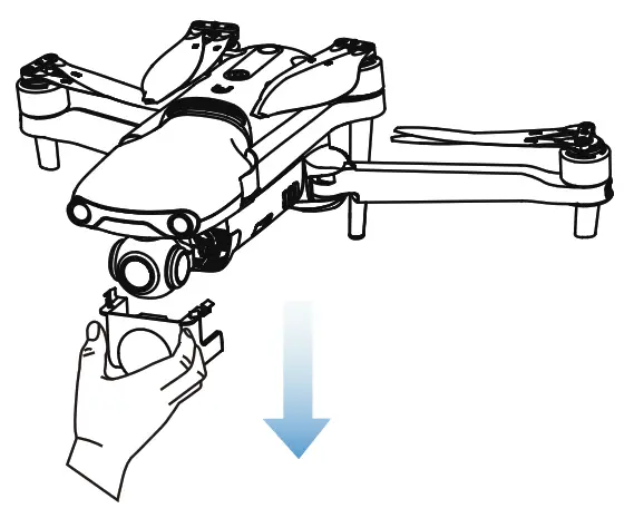
PREPARING THE AIRCRAFT
- Remove the Gimbal
- Unfold the arms and propellers
![]() IMPORTANTPower off the aircraft before folding it. Fold in the rear arms and propellers first, and then the front arms.
IMPORTANTPower off the aircraft before folding it. Fold in the rear arms and propellers first, and then the front arms.
INSTALLING NEW PROPELLERS
Because the propellers come attached to the aircraft, the following instructions apply if you need to reinstall propellers. Propellers must be undamaged and firmly attached.The white-coded propellers should be paired with the white-coded motors.♦ Attaching the Propellers
- Verify that the aircraft is powered
- Locate and match the propeller to each
- Press each propeller down firmly and rotate in the lock direction to securely attach the propeller.
♦ Detaching the Propellers
- Power off the
- Press each propeller down firmly and rotate in the unlock direction to detach the propeller.
Legend
![]() Lock Direction: Fasten the propeller by rotating it as indicated.
Lock Direction: Fasten the propeller by rotating it as indicated.![]() Unlock Direction: Unfasten the propeller by rotating it as indicated.
Unlock Direction: Unfasten the propeller by rotating it as indicated.![]() Black-coded propeller > Pairs with > Black-coded motor
Black-coded propeller > Pairs with > Black-coded motor![]() White-coded propeller > Pairs with > white-coded motor
White-coded propeller > Pairs with > white-coded motor
![]() WARNINGPower off the aircraft before attaching or detaching propellers.
WARNINGPower off the aircraft before attaching or detaching propellers.
![]() IMPORTANTWear protective gloves when attaching or detaching propellers.
IMPORTANTWear protective gloves when attaching or detaching propellers.
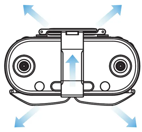
PREPARING THE REMOTE CONTROL
- Unfold the model device holder and antennas
- Position the antennas vertically in order to ensure the strongest possible signal.
POWERING UP
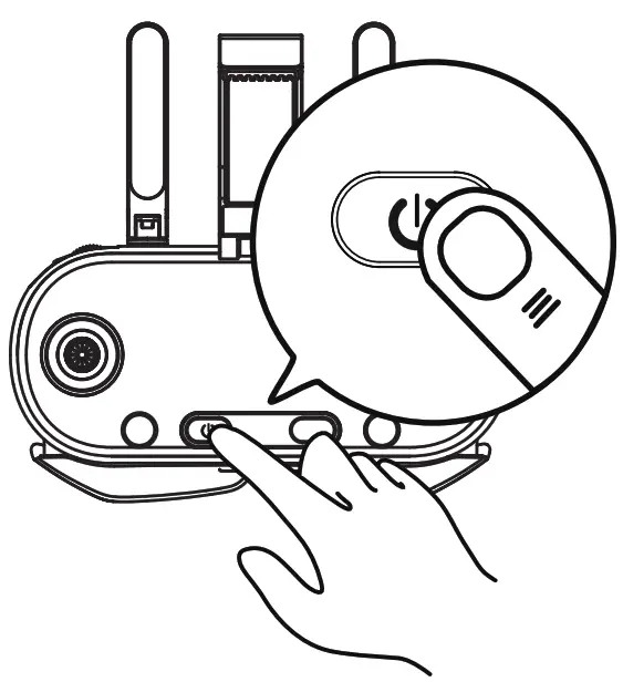
- Turn on the remote Press and hold the power button for 2 seconds.
- Turn on the aircraft. Press and holder the aircraft power button for 3 seconds. The current battery level will be clearly displayed.
TAKEOFF
- Place aircraft on a level Stand well clear of the rear of the aircraft.
- Start the motors by holding both command sticks for two seconds in one of these positions:
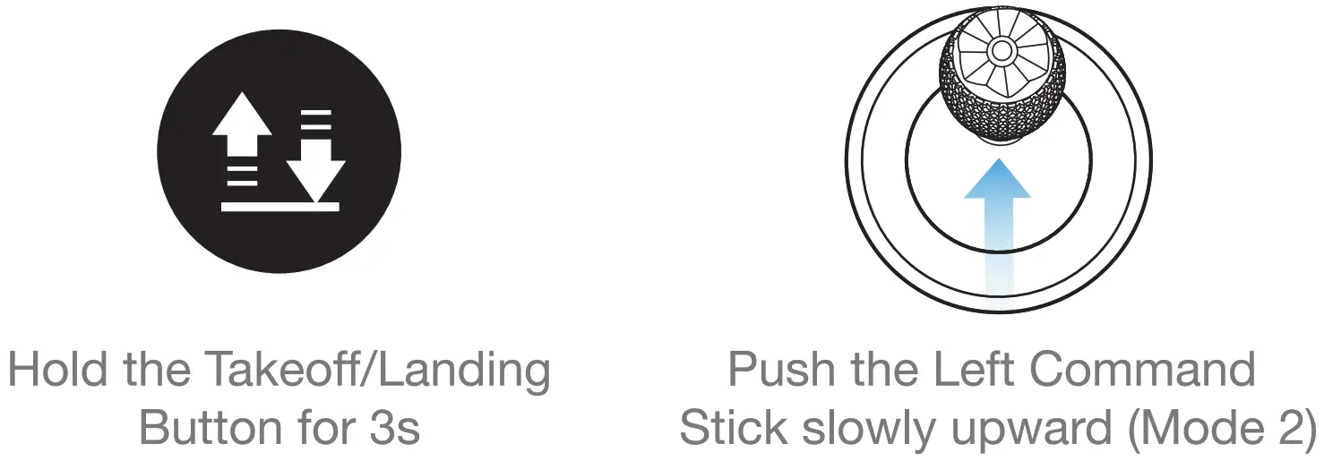
- With the motors spinning, choose one of the following methods to take off:
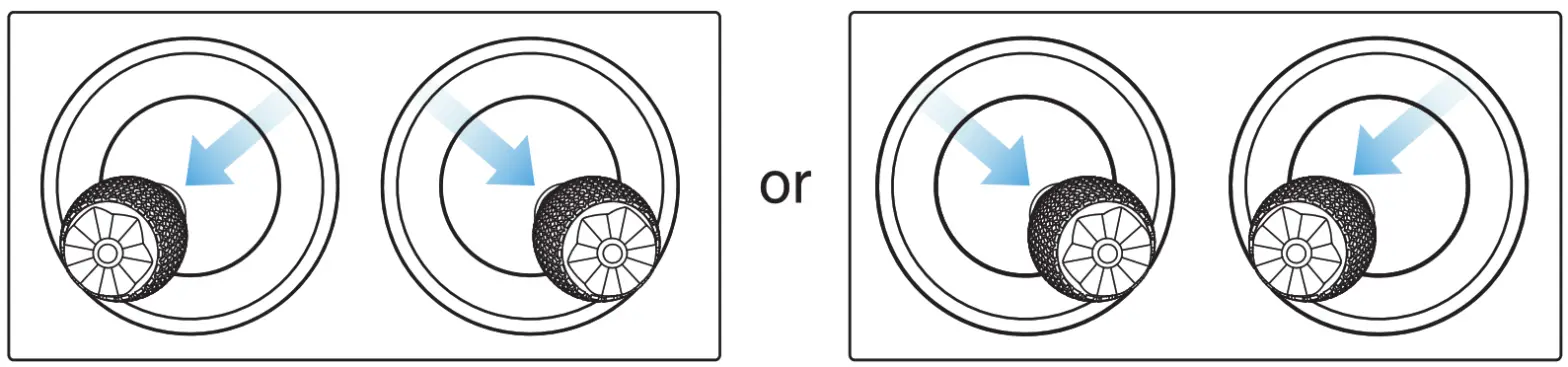
NOTE: Before takeoff, place the aircraft on a flat and level surface and face the rear side of the aircraft towards you.
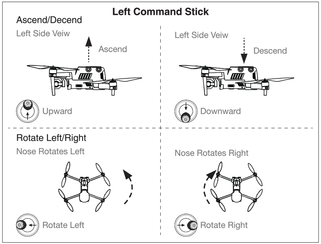
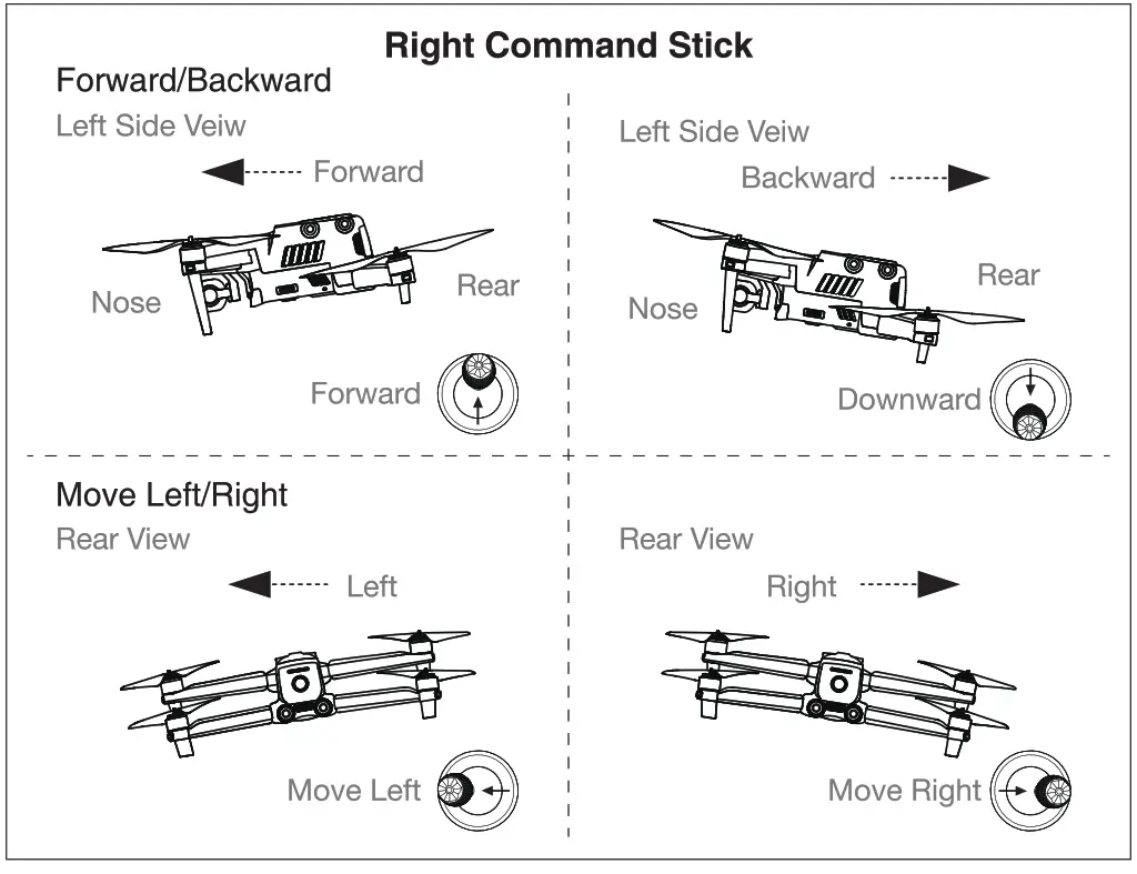
COMMAND STICK CONTROLS(MODE 2)
report this ad![]()
WWW.AUTELROBOTICS.COMÔ 2020-2021 Autel Robotics Co., Ltd. All Rights Reserved
[xyz-ips snippet=”download-snippet”]