Installation and User Manual
![]()
Simple. Robust. Reliable.
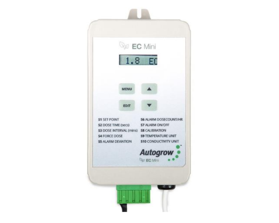
Autogrow EC Mini Controller
- Measures EC, CF or TDS
- Doses nutrients on-demand
- Displays EC (CF/TDS), Dose Count Total (DCT) and Dose Count per hour (DC/h)
- Direct drive dosing pumps (keeps costs down)
Important notice:When using automatic dosing equipment, all chemicals must be in a form diluted state, especially acids and alkalis.
We recommend diluting your nutrients 1-part nutrient to 4 parts water while dialling in your dosing settings.
Introduction
The EC Mini Controller is from a family of monitors and dosers that have been proven over many years. This controller has built upon this pedigree of simplicity and innovative features.
FeaturesThe EC Mini Controller may be used as a simple monitor or may have two peristaltic pumps added to turn it into a complete dosing control system.
Failsafe DosingDosing may be inhibited if any of the following is detected:
- EC outside limits detected
- Dose count per hour exceeded (DC/h)
These are useful if a leak should develop or the pump fail and should prevent continuous dosing.
AlarmsThe alarms can be enabled to operate on the controller when the EC or DC/h deviates outside the user setpoint.
OutputsThe 24VDC outputs allows direct drive of 24VDC peristaltic pumps. Always ensure that the current capability of the power adapter is greater than the current draw of the pumps. The pumps that we supply take a peak current of 1.2A. The controller is normally supplied with a 2.5A power supply.
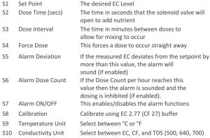
The menu structure of the EC Mini Controller is split into 2 sections – Readings and Settings. Toggling between the two menus is achieved by pressing the Menu button. Once in the Readings or Settings Menu, navigation is achieved through the Up and Down arrow keys. Settings may be changed by holding down the Edit button and then pressing the Up or Down arrow keys. The new setting is automatically saved when the edit button is released. Some Readings can be zeroed; to do this hold down the Edit button and then press the Down arrow.
ReadingsDisplay ECDisplay Dose Count Total (DCT)Display Dose Count per Hour (DC/h)Display System Status
Settings
Dose and Dose Interval Timing
Dose times and interval are set by trial and error. The smaller the reservoir, the smaller the dose times need to be. The strength or concentration of your stock solutions will also affect the dose time setting. The stronger the stock solution, the shorter the time the pump runs. If you are using a small reservoir tank you must ensure that your stock solutions are very dilute.
Ideally, you are trying to achieve a dose time such that the EC(TDS) goes up by about 0.1EC (50 ppm) for each dose. If you need to set the dose time to a very small number to achieve this, then you need to dilute the stock solution. The minimum time that any pump should run for is 1 second.
The dose interval is set to allow time for a dose to fully mix in before the controller makes the decision as to whether another dose is required. Normally set to 1 minute for a small tank and up to 10 minutes for very large systems.
Every system is unique and will have its own requirements. If you would like help to determine the best dose times and intervals, please contact
Installation
Mount the mini controller within 5 meters of the sample pot. It should be mounted in a cool, dry place out of direct sunlight. The sample pot is typically mounted just above the reservoir tank. This ensures the flow through the sample pot is unlikely to stop completely if there is a partial loss of pressure in the system (e.g. pump filter partly blocked).
Peristaltic PumpsYou can direct drive 24VDC peristaltic pumps from the controller, maximum current 2.5A.
Typical Installation using Peristaltic Pumps

Wiring Diagram
EC Mini Controller(viewed from front)
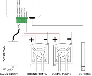
Note: that all the connections marked 24V Common are connected internally and you may connect the return wire from any solenoid valve or pump to any of these commons. The 24V live wire is normally marked by a white stripe or white printing along its length.
Maintenance
Cleaning the EC ProbeClean the face of the probe. Remove the shroud from the end of the probe and use a little kitchen liquid scouring cleaner such as “Jif” or “SoftScrub” on a clean “Scotchbrite” nylon scouring pad. Alternatively, use 600 grit wet-and-dry paper with the cleanser. Use a circular motion to scour the face of the probe and then rinse well in running water. Do not touch the face of the probe with your fingers, shake off any residual water. Replace the shroud.
Calibrating ECEvery week you should check the EC calibration. To do this, place the probe in the EC 2.7 (CF 27) standard solution and allow to stand for 5 minutes. The reading should be 2.8 +/- 0.1 mS/cm. If not, navigate to the calibration screen, hold in the edit key, and use the up/down arrows to correct the displayed reading. When the edit button is released, the new calibration will be saved.
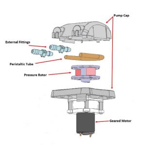
Peristaltic Pump MaintenanceThese require very little maintenance. It is important to lubricate the inner peristaltic tubing every 3-4 months. Simply pinch the sides of the pump head to remove it from the motor. Put 2-3 drops of lubricant on the tube at each roller point. This lubricant can be purchased via your distributor.

General MaintenanceFrequently inspect your system for leaks, repair as soon as possible. Water dripping onto power supplies or pumps could cause them to fail. Ensure the controller, pump unit and power supply are kept clean and shielded from all water splashes and vapours.
Fault Finding
- Unit is completely dead – i.e. no display, no power light, no outputs. Check the power pack is functioning, (by measuring with a voltmeter if possible), is plugged in, switched on and properly connected to the controller. If unit still fails to function, the probability is the internal 4A fuse (20mm x 5mm miniature glass fuse) may have blown. Most likely cause is that wires connecting to the pumps have touched together and shorted out. To fix this it is important to clear the fault first. Inspect all wiring and ensure all wires are well insulated right to the point where they enter the terminal block. Then replace the fuse with a genuine 4A fuse. DO NOT ATTACH WIRE OR ALUMINIUM FOIL ACROSS IT.
- EC calibration is out or EC reading varies. Ensure there is a small, non-turbulent flow of solution past the face of the EC probe. Ensure probe has been properly cleaned and is free from grease or oil (water should wet the face and should not bead).
- EC overdoses. Check there is adequate flow through the sample pot and the EC dose time is not excessive. Each dose should change the EC by 0.1 (1CF or 50ppm)
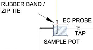
- Erratic EC Readings. A possible air bubble in the shroud on your EC Probe. Remove the shroud and use a zip tie or rubber band to hang the probe from the top of the sample pot (see pic), just making sure the bottom of the EC probe does not sit on the bottom of the sample pot.
Specification
- 2 outputs for nutrient parts A & B
- Output voltage same as supplied voltage 12V to 24V AC or DC, normally 24V DC supplied (Please contact Autogrow before using an AC power supply)
- Nutrient measurement units EC, CF or TDS (TDS @ 500/640/700)
- Measured range 0.1 to 9.9EC, 1 to 99CF, 0 to 4999 ppm
- Nutrient resolution 0.1 mS/cm, 1 CF, 50 ppm
- Nutrient measurement accuracy +/- 0.1 EC, 1 CF or 50ppm – temperature compensated
- Nutrient dosing range 0.1EC to 5.9EC, 1 to 59CF, 50ppm to 2999 ppm
- Temperature resolution and accuracy 1oC, 2oF
- Temperature measuring range 0-50oC, 32-125oF
- Operating temperature range 0-45oC, 32-110oF (and not in direct sunlight)
- Dosing fail safe shut-off (can be disabled)− if nutrient is below 0.1EC, 1CF, 50ppm or greater than 6.0EC, 60CF, 3000ppm
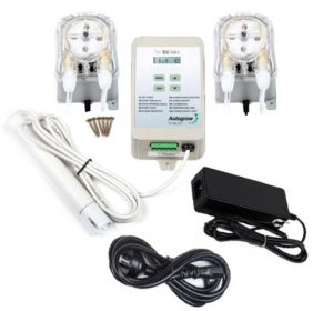
In the box:HKIT-EC-001-01
- 1 x EC Mini controller
- 1 x 24V DC 2.5A power supply with universal plug
- 1 x EC Probe
- 1 x Mounting hardware
- 1 x Instruction manual
HKIT-EC-002-01
- 1 x EC Mini controller
- 1 x 24V DC 2.5A power supply with universal plug
- 1 x EC Probe
- 1 x Mounting hardware
- 1 x Instruction manual
- 2 x Mini Peristaltic Pumps 350ml/min
Warranty and ReplacementsIf you have equipment purchased from Autogrow and it has developed a fault, please complete this form so that our support staff can diagnose the problem.
- Visit this page for Terms and Conditions https://autogrow.com/terms-conditions
- Visit this page for the RMA Form https://autogrow.com/support-and-rma-form
- Contact the distributor you bought the product from.
- Contact
www.autogrow.comNorth America (+1) 707 206 2220Global (+64) 9 415 2380
Copyright ©2020 Autogrow Systems Limited
Autogrow EC Mini Controller Installation and User Manual – Autogrow EC Mini Controller Installation and User Manual –
Questions about your Manual? Post in the comments!
[xyz-ips snippet=”download-snippet”]