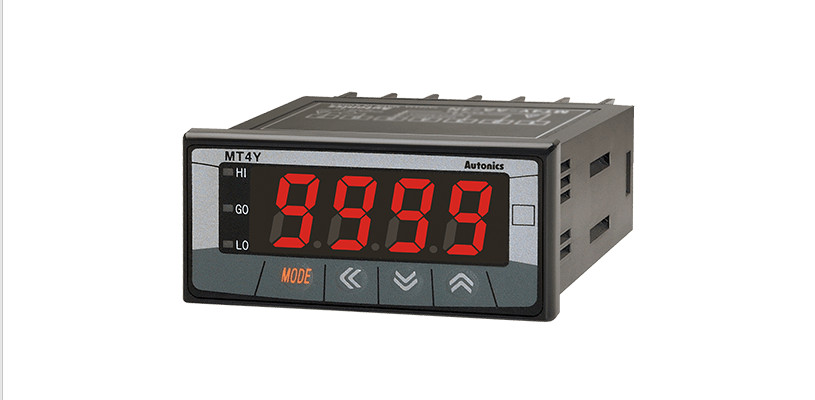
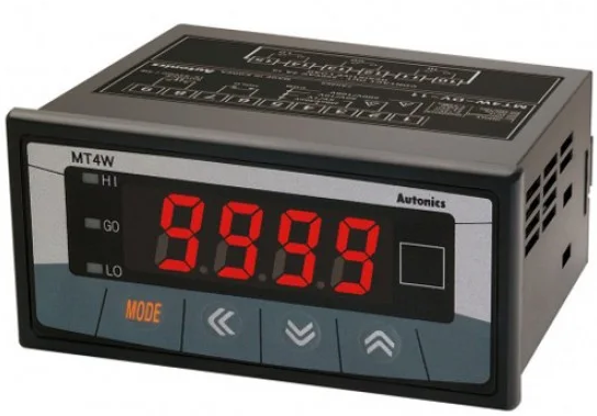
Autonics Panel Meter
Thank you for choosing our Autonics products.Please read the following safety considerations before use.
Safety Considerations
‘Please observe all safety considerations for safe and proper product operation to avoid hazards symbol represents caution due to special circumstances in which hazards may occur
Warning Failure to follow these instructions may result in serious injury or deathCaution Failure to follow these instructions may result in personal injury or product damage.
Warning
- Fail-safe device must be installed when using the unit with machinery that may cause serious injury or substantial economic loss. (e.g. nuclear power control, medical equipment, ships, vehicles, railways, aircraft, combustion apparatus, safety equipment, crime/disaster prevention devices, etc.)Failure to follow this instruction may result in personal injury, economic loss or fire.
- Do not use the unit in the place where flammable/explosive/corrosive gas, high humidity, direct sunlight, radiant heat, vibration, impact, or salinity may be present.Failure to follow this instruction may result in explosion or fire.
- Install on a device panel to use.Failure to follow this instruction may result in fire or electric shock.
- Do not connect, repair, or inspect the unit while connected to a power source.Failure to follow this instruction may result in fire or electric shock.
- Check ‘Connections’ before wiring.Failure to follow this instruction may result in fire.
- Do not disassemble or modify the unit.Failure to follow this instruction may result in fire or electric shock.
Caution
- When connecting the power/measurement input and relay output, use AWG 24(0.20mm2) to AWG 15(1.65mm2) cable and tighten the terminal screw with a tightening torque of 0.98 to 1.18N.m.Use proper cables for the rated load current.Failure to follow this instruction may result in fire or malfunction due to contact failure.
- Use the unit within the rated specifications.Failure to follow this instruction may result in fire or product damage.
- Use dry cloth to clean the unit, and do not use water or organic solvent.Failure to follow this instruction may result in fire or electric shock.
- Keep the product away from metal chip, dust, and wire residue which flow into the unit.Failure to follow this instruction may result in fire or product damage.
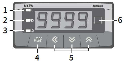
Front Panel Identification
- HI: High output indication of preset
- GO: GO output indication of preset
- LO: Low output indication of preset
- : MODE Key
- :
 Control key
 - Unit label part※ There are no 1, 2, 3 output indication in Indication type.
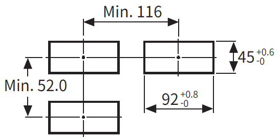
Panel Cut-Out
Connections
Use teminals of size specified below.Use the Copper-conductor wire with the temperature class 60℃.

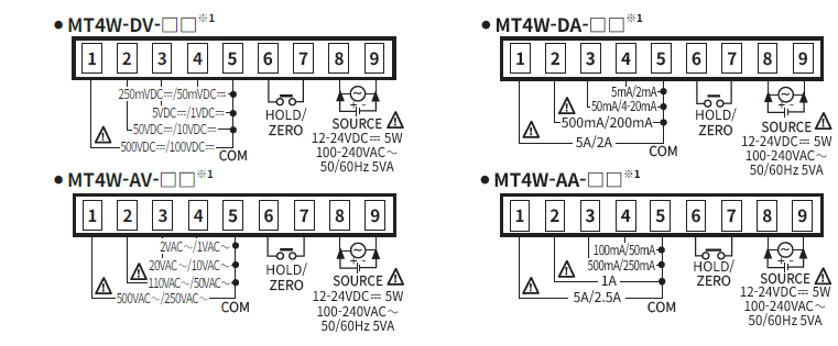
<Input>
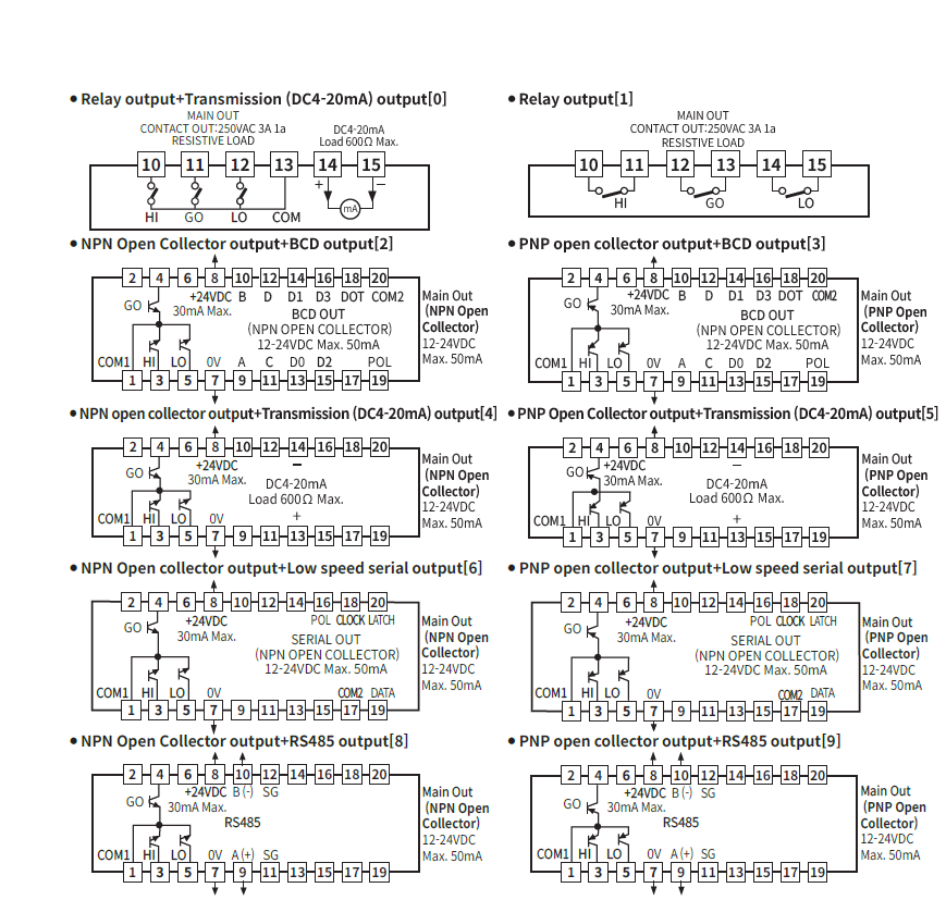
<Option>
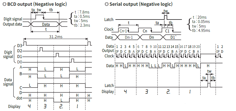
Time Chart Of Serial Output And BCD Output
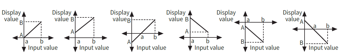
Prescale Function [PA1 : H-SC/L-SC]
This function is to display setting (-1999 to 9999) of particular High/Low-limit value in order to display High/Low-limit value of measured input.If measured inputs are ‘a’ or ‘b’ and particular values are ‘A’ or ‘B’, it will display a=A, b=B as below graph.
Error Display Function

Error display is released automatically when it is in the measured and display range.‘LLLL’ is displayed when the input specification is DC.After flashing ‘OVER’ 2 times when it exceeds the zero range, it returns to RUN mode.
The above specifications are subject to change and some models may be discontinued without notice.Be sure to follow cautions written in the instruction manual and the technical descriptions (catalog, homepage).
Specifications
| Model | MT4W- -4 | MT4W- -1 |
| Power supply | 100-240VACᜠ 50/60Hz | 12-24VDCᜡ |
| Allowable voltage range | 90 to 110% | |
| Power consumption | 5VA | 5W |
| Display method | 7 Segment LED display (red) (Character height: 14.2mm) | |
| Display accuracy | 23℃±5℃ – DC Type: F.S.±0.1% rdg±2digit / AC Type: F.S.±0.3% rdg±3digit
DC/AC Type: F.S.+0.3% rdg +3digit max. only for 5A terminal -10℃ to 50℃ – DC/AC Type: F.S.±0.5% rdg±3digit |
|
| Input | DC Voltage/Current, AC Voltage/Current, AC Frequency | |
| Max. allowable input | 110% for each measured input range | |
| A/D conversion method | ΣΔ (Sigma Delta) ADC | |
| Sampling cycle | DC type: 50ms, AC type: 16.6ms | |
| Max. indication range | -1999 to 9999 (4digit) | |
| Preset output | • Relay output – Contact capacity: 250VACᜠ 3A, 30VDCᜡ 3A/Contact composition: N.O (1a)
• NPN/PNP Open Collector output – 12-24VDCᜡ ±2V 50mA Max. (Load resistance) |
|
| Sub output (Transmission output) | • RS485 communication output – Baud rate:1200/2400/4800/9600, Communication method : 2-wire
half duplex,Synchronous method: Asynchronous method , Protocol : Modbus type • Serial/BCD output – NPN Open collector output, 12-24VDCᜡ Max. 50mA (Resistive load) • DC4-20mA output – Resolution: 12,000 division (Load resistance max. 600Ω), Response time:Max. 450ms |
|
| Insulation resistance | Over 100MΩ (at 500VDCᜡ megger) between external terminal and case | |
| Dielectric stength | 2,000VACᜠ for 1minute between external terminal and case | |
| Noise immunity | ±2kV the square wave noise (pulse width: 1㎲) by the noise simulator | |
| Vibration | Mechanical | 0.75mm amplitude at frequency of 10 to 55Hz (for 1 min) in each X, Y, Z direction for 2 hours |
| Malfunction | 0.5mm amplitude at frequency of 10 to 55Hz (for 1 min) in each X, Y, Z direction for 10 min | |
| Shock | Mechanical | 100m/s² (approx. 10G) in each X, Y, Z direction for 3 times |
| Malfunction | 300m/s² (approx. 30G) in each X, Y, Z direction for 3 times | |
| Relay life cycle | Mechanical | Min. 20,000,000 operations |
| Malfunction | Min. 100,000 operations (250VACᜠ 3A Load current) | |
| Environ-
ment |
Ambient
temperature |
-10 to 50℃, Storage: -20 to 60℃ |
| Ambient
humidity |
35 to 85%RH, Storage: 35 to 85%RH | |
| Insulation type | Double insulation or reinforced insulation
(Mark: , dielectric strength between the measuring input part and the power part: 1kV) |
|
| Approval | ᜢ ᜧ | ᜢ |
| Weight※1 | Approx. 326g (approx. 211g ) |
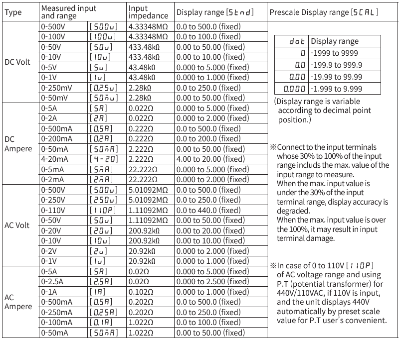
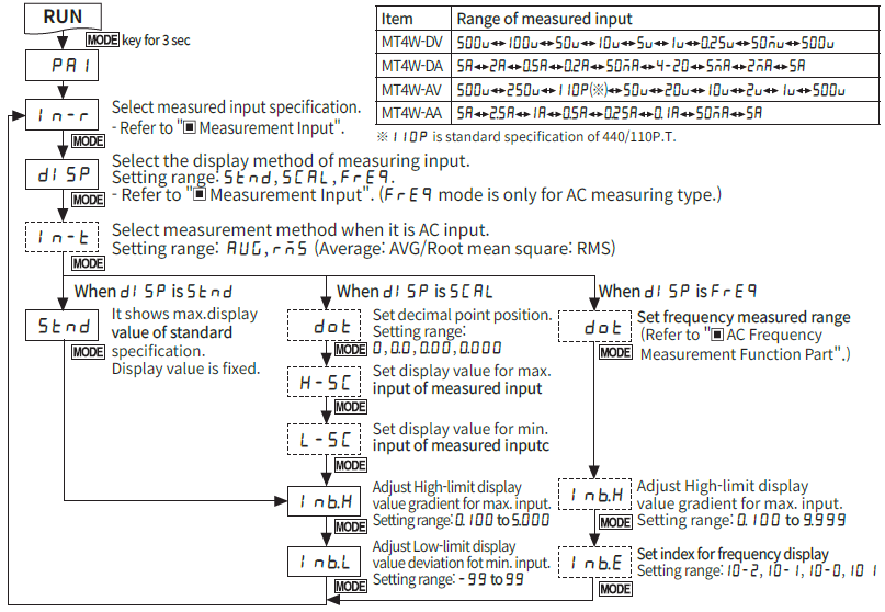
Measurement Input [PA 1: IN-R]
Display Cycle Delay Function [PA 2 : DIsT]
In some applications the measured input may fluctuate which in turn causes the display to fluctuate.By adjusting the display cycle delay function time at DIS.T of parameter 2, the operator can adjust the display time within a range of 0.1 sec to 5 sec. For example, if the operator sets the display cycle time to 4.0 sec, the display value displayed will be the average input value over 4 sec and also will show any changes if any every 4 sec.
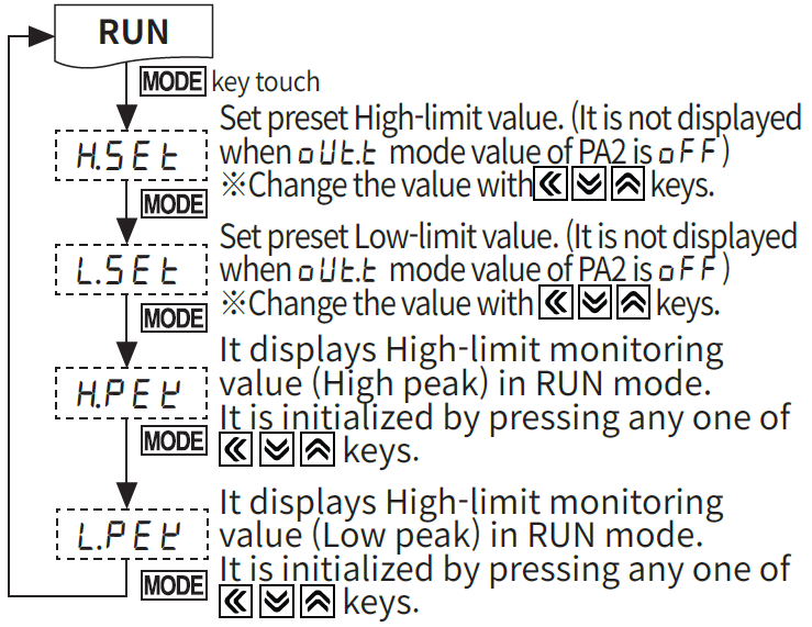
Monitoring Max./Min.Display Value Function[PA 0: hPEK/lPEK,PA 2: PEkT]
It monitors Max./Min. display value based on the current displays value and then displays the data at hPEK, lPEK of parameter 0. Set the delay time (0 to 30 sec) at PEkTof parameter 2 in order to prevent malfunction caused by initial over current or over voltage, when monitoring the peak value. Delay time is 0 to 30 sec and it starts to monitor the peak value after the set time. When pressing any one of ![]() key at hPEK, lPEK of parameter 0, the monitored data is initialized.Monitoring function is not displayed when the delay time is set as “00 S” at PEkT of parameter 2.
key at hPEK, lPEK of parameter 0, the monitored data is initialized.Monitoring function is not displayed when the delay time is set as “00 S” at PEkT of parameter 2.
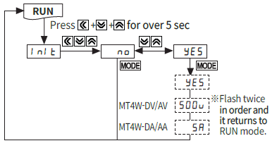
Initialization Function
This function is to initialize parameter as factory difault.
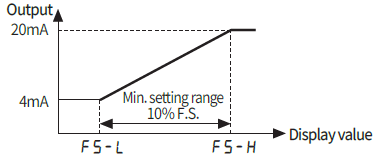
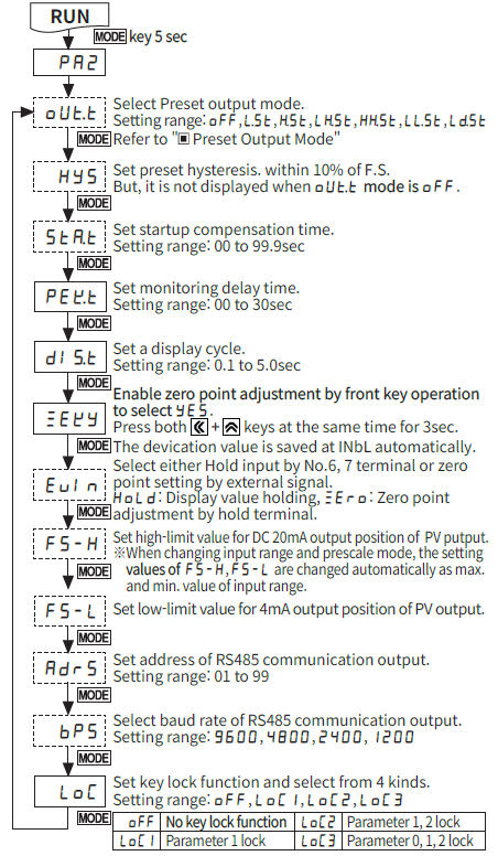
Current Output (DC4-20mA) Scale adjustment function [PA 2 : FS-H/ FS-L]
output DC 4-20mA.It sets display value for 4mA at FS-L and 20mA at FS-H and the range between FS-H and FS-L should be 10% F.S. (When it sets as under 10% F.S., it changed as over 10% F.S. automatically.) Preset display value is fixed to output as 4mA at under FS-Land 20mA at over FS-H.
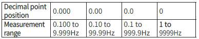
AC Frequency Measurement Function [PA1 : DISP]
It measures input signal frequency when it is AC input.It uses fixed decimal point[PA1:DOT], measured range can be changed by setting and measured range of decimal point position is as below chart.It is available to adjust the upper gradient at [PA1:INbH] and [PA1:INbE]. In order to measure frequency normally, input signal, over 10% F.S. of measured range should be supplied. Please select the proper point of measurement terminal.
- Measured rangeAccuracy of frequency measurement: Below 1kHz, F.S.±0.1rdg ±2digit. From 1kHz to 10kHz, F.S ±0.3rdg ±2digit.
- INB.H : 00.100 to 9.999 [Gradient adjustment of high value]
- INB.E : 10-2, 10-1, 10-0, 101 [Index adjustment of INB.H]
 Accuracy of frequency measurement: Below 1kHz, F.S.±0.1rdg ±2digit. From 1kHz to 10kHz, F.S ±0.3rdg ±2digit.
Error Correction Function [PA 1 : INbH/ INbL]
It corrects display value error of measured input.INB.L: ±99 [Adjust deviation of low value]INB.H: 5.000 to 0.100 [Correct gradient (%) of high value]Diplay value= (Measured value × INB.H) + INB.LWhen the measured range is 0 to 500V, and the display range is 0 to 500.0. If the low display value is “1.2” to 0V input, set -12 as the INbL value to display “0.0” by adjusting the offset of the low value.The display value to the 500V measured input varies by adjusting the offset of the low value. If this display value is “501.0”, calculate 500.0/501.0 (the desired display value/the display value), and set the 0.998 correction value as the INbH to display “500.0” by adjusting the gradient of the high value.The offset correction range of INbLis within -99 to 99 for D-0, D-1 digit regardless of dicimal point.
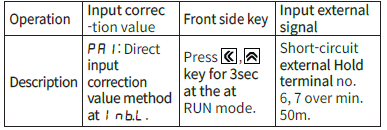
Zero Adjustment Function
It adjusts the indication value of the optional configured input value as zero by force, zero point error can be adjusted with 3 ways as below.When zero point adjustment with front key and Hold terminal is finished normally, zero point of measurement terminal is displayed and the adjusted value is saved at INbL automatically.
Refer to description “![]() Error Correction Function”
Error Correction Function”![]() ” ErrorDisplay Function”,
” ErrorDisplay Function”,![]() ” Parameter 2″ for function and error.
” Parameter 2″ for function and error.
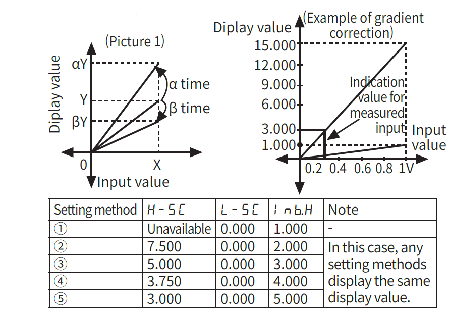
Gradient Correction Function [PA 1 : INbH]
It corrects the gradient of prescale value and display value. (Picture 1) Display value Y can be used as α, β times against X input value by correction function[ INbH] and used as correction function of max. display value[ H-SC].Adjustment range is 0.100 to 5.000 and multiply current gradient.
Ex)Input:200mVDCᜡ, Display:3.000 for MT4W-DV type
- Select 0-1VDCᜡ (1V) for measured input in Parameter 1.
- Standard specification in input: 0-1VDCᜡ and 1.000 therefore it has to be 15.000[ H-SC] for 1VDCᜡ (Input) in order to display 3.000 for 200mVDCᜡ (Input).But it is unable due to setting range is 9.999
- In this case, please check below chart.Please set as INbH× H-SC = 15.000
Preset Output Mode [PA 2 : OUtT]
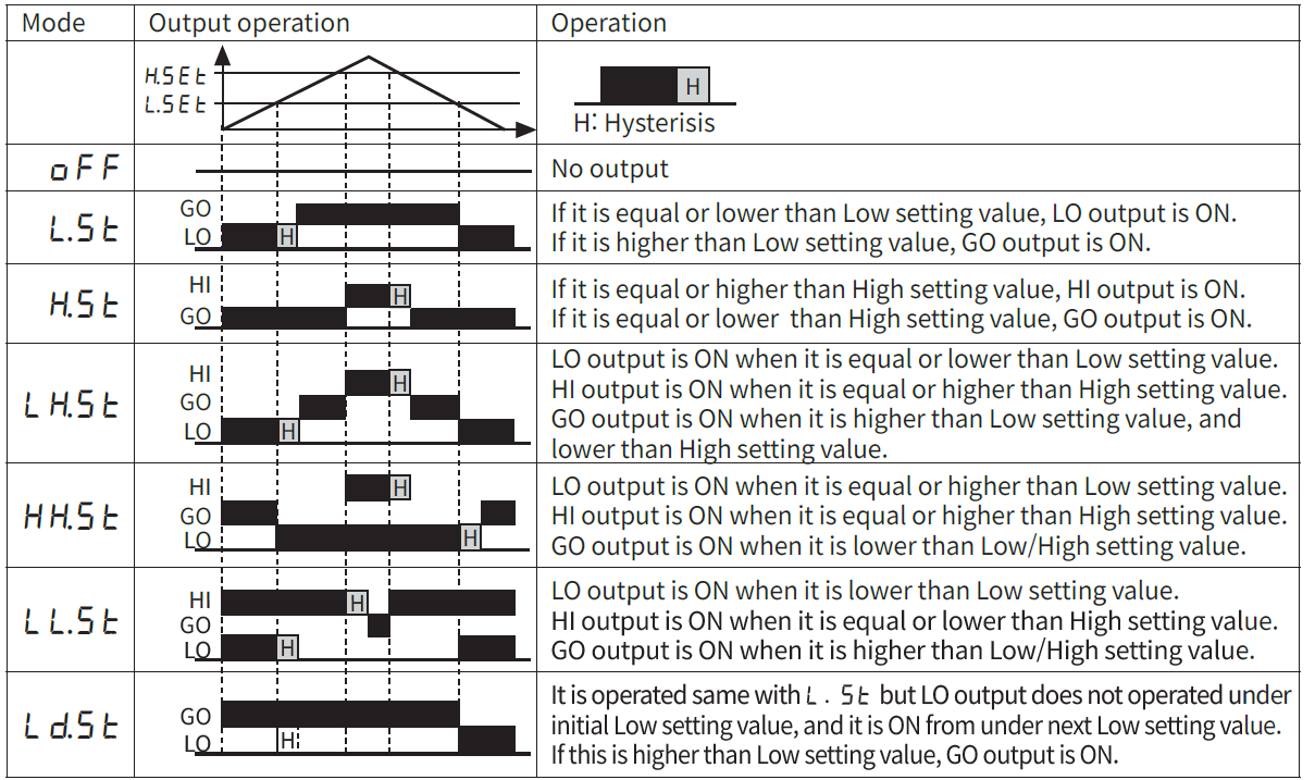
hSETis displayed according to the setting of output operation mode, when user sets “OFF”, hSET/ lSETare not displayed.
Startup Compensation Timer Function[PA 2 : STaT]
This time function limits the operation of an output until the measured input (overvoltage or inrush current) is stable at moment of power on. All outputs are off during startup compensation time setting after power is supplied.Setting range: 00.0 to 99.9 (unit: sec), Factory default: 00.0
Parameter
| Parameter | Display | Function | Note | |
|
PA1 (Parameter1) |
IN-T | Input type | Selectable RMS/AVG in AC type | Available AC type only. |
| IN-R | Input range | Selection of input range | – | |
| DISP | Display | Selection of display type | Setting range: STND, SCAL, FREQ | |
| STND | Standard | Standard scale range | Display Max. display value of STND | |
| FREQ | Frequency | Frequency display | Available AC type only. | |
| SCAL | Scale | Scale range | These are displayed at SCAL
It sets max. display value/min. display value (-1999 to 9999) |
|
| H-SC | High scale | Set max. value of display range | ||
| L-SC | Low scale | Set min. value of display range | ||
| DOT | Dot | Set decimal point position | It is dispayed at SCAL /FREQ only and set
the decimal point position |
|
| INbH | Input bias high | Correct High-limit value
of display value |
STND/ SCAL: Correction range 0.100 to 5.000
FREQ: Correction range 0.100 to 9.999 |
|
| INbL | Input bias low | Correct Low-limit value
of display value |
Setting range: -99 to +99 | |
| INbE | Input bias
exponent |
Set display index of
frequency mode |
Setting range: 10-2, 10-1, 100, 101 | |
|
PA2 (Parameter2) |
OUtT | Out type | Set operation mode of
preset output |
Setting range: OFF, lST, hST, LhST,
HhST, LlST, LdST |
| HYS | Hysteresis | Set hysteresis value | Setting range: 1 to 10% F.S. | |
| STaT | Startup compen
-sation time |
Set startup compensation time. | Setting range: 00 to 99.9sec | |
| PEkT | Peak time | Set monitoring delay time
for peak value (sec) |
Setting range: 00 to 30sec | |
| DIsT | Display time | Set sampling time (sec) | Setting range: 0.1 to 5.0 sec
(Variable by 0.1sec) |
|
| ZERO | Zero Key | Set usage of front side zero
adjustment key |
NO: Not use front side zero adjustment key
YES: Use front side zero adjustment key |
|
|
EVIN |
Event Input | Set external terminal (6, 7)
function |
HOLD: Use external terminal as Hold terminal
ZERO: Use external terminal as zero point adjustment terminal |
|
| FS-H | Full scale High | Set the upper value output
point or PV output |
Min. set range: Min. 10% F.S. | |
| FS-L | Full scale Low | Set the lower value output
point or PV output |
Max. set range: Max. FS-H 10% | |
| ADRS | Address | Set communication address | Setting range: 01 to 99 | |
| BPS | Bit per second | Set baudrate (bps) | Setting range: 1200, 2400, 4800, 9600 | |
| LOC | Lock | Set lock function | Setting range: OFF, LOC1, LOC2, LOC3 | |
|
PA 0 (Parameter0) |
hSET | High set | Set High setting value | Setting range can be set within the
display range of STND/ SCAL |
| lSET | Low set | Set Low setting value | ||
| hPEK | High peak | Max. value by data monitoring | Initializes the monitored data value by
pressing any one of keys. |
|
| lPEK | Low peak | Min. value by data monitoring |
Parameter Setting
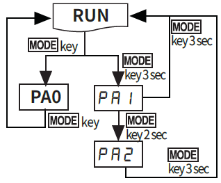
- Press key in RUN mode and it enters PA 0 group.
- Press key for over 3 sec in RUN mode, it displays [PA1].
- Press key for over 5 sec in RUN mode, it displays [PA2] after [PA1].When pressingkey continually, it stops displaying at [PA2].
- It is advanced to current display parameter releasing key at [PA1] or [PA2].
- Presskey for over 3 sec in any parameter groups, it returns to RUN mode.
- If any key is not entered for 60 sec in each parameter, it returns to RUN mode.
- After returning to RUN mode, press key within 2 sec, it returns to previous parameter. (Refer to the below descriptions of each parameter group.)
- PA 0 group cannot be entered when preset output mode of [PA2] group is OFF.
Parameter 0
Parameter 1
Parameter 2
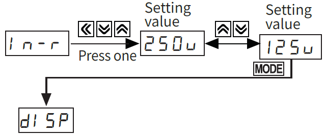
Change The Parameter Setting Value
- Advance to the parameter to be changed when pressingkey continuously in RUN mode and releasingkey at the parameter.(Refer to “ Parameter Setting”)
- When pressingkey in each parameter, the initial mode of the parameter is displayed.(Refer to the description of each parameter.)
- When pressing one of , , keys in display mode, the saved setting value is displayed.
- Change the setting value byor key when setting value flashes.Ex) Change AC type measured input from 250V to 125V.
- When confitming the setting value with key, the changed setting value flashes twice and enters into the next setting.
- It returns RUN mode from parameter by pressingkey for 3 sec.

User Manual For Communication
Visit our website (www.autonics.com) to download the user manaul for communication of MT series.
Cautions during Use
- Follow instructions in ‘Cautions during Use’. Otherwise, It may cause unexpected accidents.
- 12-24VDC power supply should be insulated and limited voltage/current or Class 2, SELV power supply device.
- Install a power switch or circuit breaker in the easily accessible place for supplying or disconnecting the power.
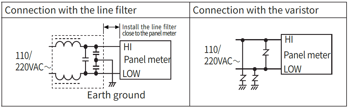
- Keep away from high voltage lines or power lines to prevent inductive noise.In case installing power line and input signal line closely, use line filter or varistor at power line and shielded wire at input signal line.Do not use near the equipment which generates strong magnetic force or high frequency noise.
- This unit may be used in the following environments.
- Indoors (in the environment condition rated in ‘Specifications’)
- Altitude max. 2,000m
- Pollution degree 2
- Installation category II
18, Bansong-ro 513Beon-gil, Haeundae-gu, Busan, Republic of Korea, 48002www.autonics.com | +82-51-519-3232 | [email protected]
References
[xyz-ips snippet=”download-snippet”]