![]()
CAM520 Pro2 Conference CameraQuick Start Guide
Package Contents
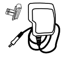
| Camera Unit | Remote Control | Power Adapter & Power Plug* |
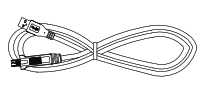
USB 2.0 Type-B to Type-A Cable (5m) |
 |
 |
 |
 |
|
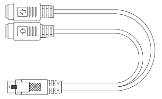
Mini DIN9 to Mini DIN8 RS232 Adapter Cable |
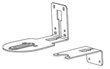
L-Mount Brackets | Screws for Mount | Drilling Paper |
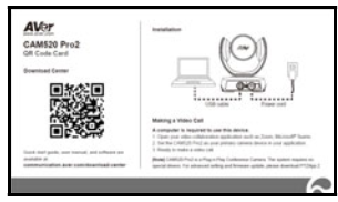
QR Code Card |
 |
 |
 |
 |
 |
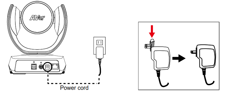
* The power plug will vary depending on the standard power outlet of the country where it is sold.
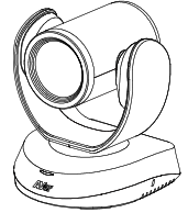
Overview
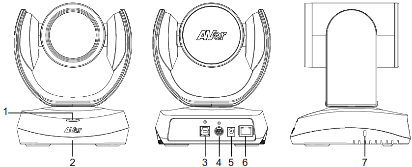
- Status LED
- IR Sensor
- USB 3.1 Type B Port
- RS232 In/Out Port
- DC 12V Power Plug
- PoE Port*
- Kensington Lock
* Power over Ethernet (PoE), compatible with IEEE 802.3AT/802.3AF. Please use CAT 5e FTP cable (not included.)
Installation
1. Connect the camera to power outlet.
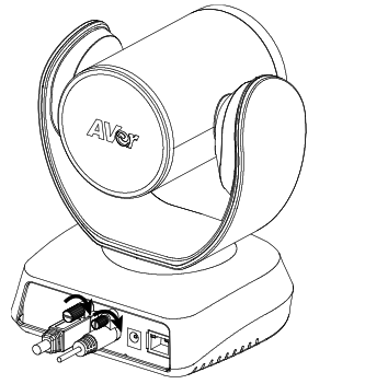
2. Connect the necessary cables.[Notes]– Secure the USB and RS232 cables with attached screws.– Make sure the cable is well connected to the connector on the camera before securing the cable.
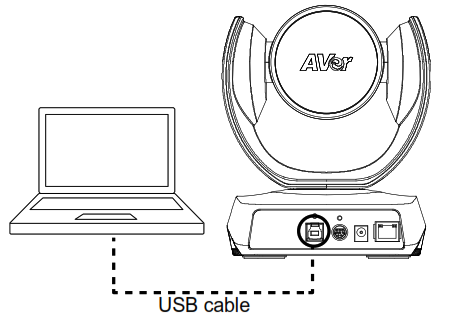
3. Connect the camera to the computer/laptop.[Notes]– Use the USB 2.0 cable included in the package.– CAM520 Pro2 has the USB 3.1 port which is USB 2.0 compatible.Maximum resolution/fps for USB 2.0 and USB 3.1 port are shown below.
| M-JPEG/fps | NV12/fps | YUV/fps | |
| USB 2.0 | /60 fps | /10 fps
/30 fps |
/10 fps
/30 fps |
| USB 3.1 | /60 fps | /30 fps | /30 fps |
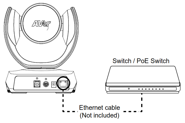
4. Connect Ethernet cable for IP streaming and remote camera control.[Notes]– To ensure the stability of IP video streaming, please use CAT 5e FTP cable.
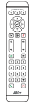
Remote Control
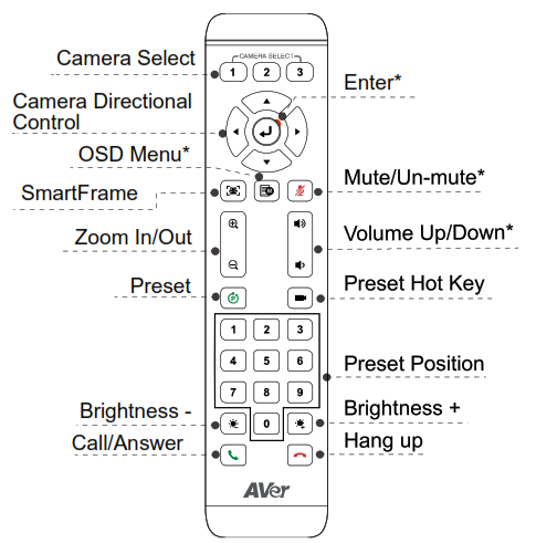
* Not supported for CAM520 Pro2
- AAA Batteries (required)
- Preset (
 ): The Preset button on the remote serves 2 functions.To Save a Preset – Move camera to desired position. Press and hold the preset button until you receive the save message on the screen. Select preset position button 0-9 to store the current camera position. Repeat steps if needed.To Load a Preset – Press the preset button and preset position button 0-9 to load a saved camera position. Repeat steps if needed.
 - Press and hold the number button “1” for 1 second to turn on or off the WDR function.
- Press and hold the number button “5” for 1 second to turn on or off the SmartFrame function.
- Press and hold the number button “8” for 1 second to enable or disable RTMP streaming function.
- Press and hold the number button “9” for 1 second to force camera to enter sleep mode. This will end any video streaming. To wake up the camera, press the button or any directional button for 1 second. This mode is not functional while USB streaming is on.
- Camera Select (): If you only have one camera and do not need to adjust any setting, the default is camera 1. If you press camera 2 or 3 on the remote control, you will find your remote can’t control your camera. In this case, please press camera 1 on your remote again.
- SmartFrame (): Press for 1 second to switch the SmartFrame function among Manual Framing/Auto Framing/ Preset Framing modes. A message (as figures shown) will display on the screen to indicate the mode.
Manual Framing Auto Framing Preset FramingNote] SmartFrame deploys face and body detection technology. People wearing masks and side facial profiles can still be detected. The maximum detection distance is 7-10 meters. Set up preset points in advance (Only for Preset point 1-9. Preset 0 is for home position).
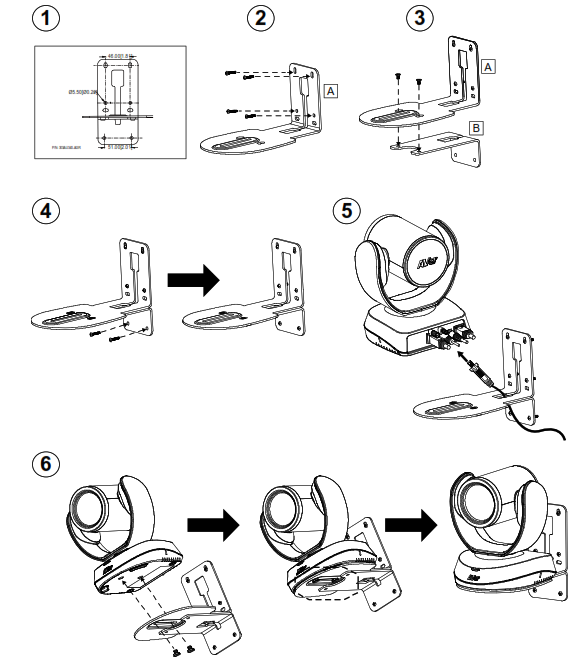
Wall Mount Installation
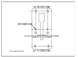
- Use the drilling paper included in the package to drill the holes in the wall where the user wants to mount the camera.
- Use the screws (not included) to secure the L-mount bracket A on the wall.[Note] For cement wall: M4 x20mm self-tapping screws (x4) + Plastic conical anchor For wooden wall: M4 x20mm self-tapping screws (x4)
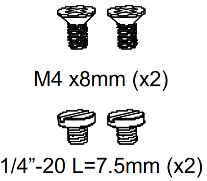
- Then, assemble the L-mount brackets A + B with 2 screws (M4 x8mm, included in the package).
- After assembling the L-mount brackets, use the screws (not included) to secure the lower part of L-mount brackets on the wall.[Note] For cement wall: M4 x20mm self-tapping screws (x2) + Plastic conical anchor For wooden wall: M4 x20mm self-tapping screws (x2)
- Pass the cables through the hole on the L-mount brackets and connect the cables to corresponding connection ports.
- Use the remaining screws (1/4”-20 L=7.5mm, included in the package) to secure the camera on the L-mount brackets.
Making a Video Call
A computer is required to use this device.1. Open your video collaboration application such as Zoom, Microsoft® Teams, Skype for Business, Skype, Google Meet, Intel® Unite™, RingCentral, BlueJeans, V-Cube, LiveOn, CyberLink U Meeting® TrueConf, Adobe Connect, Cisco WebEx®, Fuze, GoToMeeting™, Microsoft® Lync™, Vidyo, vMix, WebRTC, Wirecast, XSplit.,2. Set the CAM520 Pro2 as your primary camera device in your application (Please consult your application setup guide for details).3. Ready to make a video call.[Note] CAM520 Pro2 is a Plug-n-Play Conference Camera. The system requires no special drivers. For advanced setting and firmware update, please download PTZApp 2.
Making a Connection through the Browser
CAM520 Pro2 has an Ethernet port for IP streaming and allows administrators to remotely control and set up the camera via internet access. Moreover, CAM520 Pro2 also supports RTSP and RTMP functions. For more details, please refer to the user’s manual or contact our technical support.1. Make sure the CAM520 Pro2 has an internet access connection.2. Launch PTZApp 2* (![]() ) and connect CAM520 Pro2 to PC with USB cable.
) and connect CAM520 Pro2 to PC with USB cable.
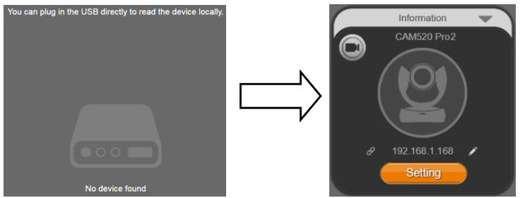
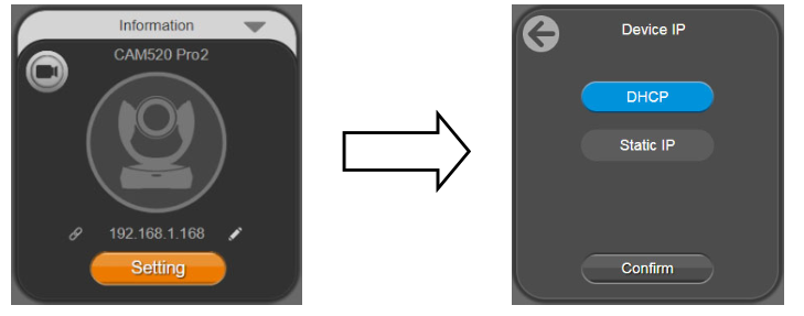
3. The camera’s default IP address is 192.168.1.168. Click the pencil icon (![]() ) to edit IP address**.
) to edit IP address**.
4. Click weblink icon (![]() ) to launch Chrome page. Please enter the password (default password is aver4321).[Note] The browser supports:
) to launch Chrome page. Please enter the password (default password is aver4321).[Note] The browser supports:
- Chrome: version 76.x or above
- Firefox: version 69 or above
- IE: Doesn’t support
5. After editing IP address, user can access web settings of the camera with only Ethernet cable connection. Unplug the USB cable.6. The main web screen is displayed as below.
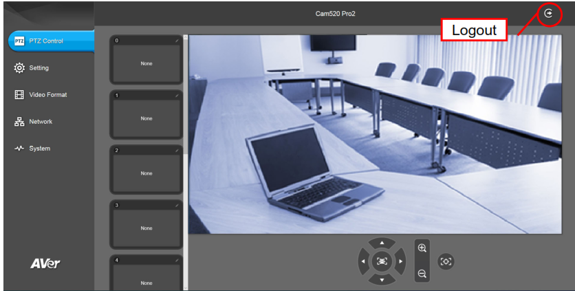
* In PTZApp2, user can change the IP address setting of CAM520 Pro2, configure the parameters of the camera, set up AI tracking functions and some advanced image settings, pan, tilt, and zoom the camera. Please refer to the user manual for details. Please go to https://www.aver.com/download-center (Global & European Headquarters) or https://www.averusa.com/business/support/ (USA) to download the PTZApp 2. After downloading, double-click on the file and follow the on-screen instructions to complete the installation. After installing the PTZApp 2, double-click on the PTZApp 2 icon to run the application.
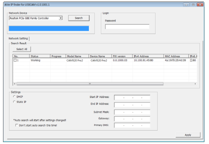
** To support IP address changes in groups, user can download AVer IP Finder app.1. Download the IP Finder from https://www.aver.com/download-center (Global & European Headquarters) or https://www.averusa.com/business/support/ (USA).2. Run the IP Finder.3. Click “Search”, and all available devices will be listed on the screen.
FEDERAL COMMUNICATIONS COMMISSION
NOTE: This equipment has been tested and found to comply with the limits for a Class A digital device, pursuant to part 15 of the FCC Rules. These limits are designed to provide reasonable protection against harmful interference when the equipment is operating in a commercial environment. This equipment generates, uses, and can radiate radio frequency energy and, if not installed and used in accordance with the instruction manual, may cause harmful interference to radio communications. Operation of this equipment in a residential area is likely to cause harmful interference in which case the user will be required to correct the interference at his own expense.FCC Caution: Any changes or modifications not expressly approved by the party responsible for compliance could void the user’s authority to operate this equipment. This device complies with part 15 of the FCC Rules. Operation is subject to the following two conditions: (1) This device may not cause harmful interference, and (2) this device must accept any interference received, including interference that may cause undesired operation.Warning:This is a class A product. In a domestic environment, this product may cause radio interference in which case the user may be required to take adequate measures. This Class A digital apparatus complies with Canadian ICES-003.Caution:Risk of Explosion if Battery is replaced by an Incorrect Type. Dispose of Used Batteries According to the Instructions.COPYRIGHT©2021 AVer Information Inc. All rights reserved.MORE HELPFor FAQs, technical support, software and user manual download, please visit:Global: https://www.aver.com/download-center/USA: https://www.averusa.com/business/support/European Headquarters: https://www.aver.com/download-center/
Technical Support:Global: https://aver.com/technical-supportUSA: https://averusa.force.com/support/s/contactsupportEuropean Headquarters: https://www.avereurope.com/technical-support/
CONTACT INFORMATION
GlobalAVer Information Inc.https://www.aver.com8F, No.157, Da-An Rd.,Tucheng Dist.,New Taipei City 23673,TaiwanTel: +886 (2) 2269 8535
USAAVer Information Inc.https://www.averusa.com668 Mission Ct.,Fremont, CA 94539Tel: +1 (408) 263 3828Toll-free: +1 (877) 528 7824Technical support: [email protected]
European HeadquartersAVer Information Europe B.V.https://www.avereurope.comWestblaak 140, 3012KM,Rotterdam, NetherlandsTel: +31 (0) 10 7600 550Technical support: [email protected]
References
Download Center | AVer Global
Technical Support ! AVer Europe
Download Center | AVer Global
Support
Downloads | USB Video Conference Camera Downloads | AVer USA
AVer中国 | 圆展科技
Download Center | AVer Global
AVer USA
Downloads | USB Video Conference Camera Downloads | AVer USA
製品資料・ソフトウェア | アバー・インフォメーション | 書画カメラ、ビデオ会議システム、タブレットPC充電保管カートの専門メーカーです| AVer Japan
AVer Europe
AVer USA
Downloads | USB Video Conference Camera Downloads | AVer USA
アバー・インフォメーション | 書画カメラ、ビデオ会議システム、タブレットPC充電保管カートの専門メーカーです| AVer Japan
Technical Support ! AVer Global
[xyz-ips snippet=”download-snippet”]