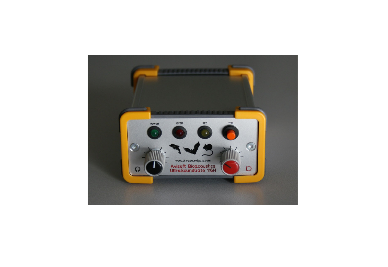
Avisoft UltraSoundGate 116H
Introduction
Thank you for purchasing Avisoft UltraSoundGate 116H. This buspowered USB device supports single-channel high-speed data acquisition at sampling rates of up to 1 MHz. The accompanying recording software Avisoft-RECORDER USGH provides either continuous or triggered direct-to-disk recording with real-time spectrogram displays.
Installation procedure
First download and install the RECORDER USGH software from the Avisoft Bioacoustics website (www.avisoft.com/downloads.htm or directly www.avisoft.com/RECORDER USGH.exe). This installation program will install both the RECORDER USGH application (rec_usgh.exe) and the required device drivers (usgh_xx16h.inf, usgh.sys) for the UltraSoundGate xx16H devices. When the installation procedure has completed, the UltraSoundGate unit can be connected to the computer. The device should then be detected as “Avisoft-UltraSoundGate 116H” and the pre-installed driver should be finally activated.
Under some circumstances it might happen that the silent installation of the device driver fails. If that happens, navigate to the Windows Control Panel > Hardware and Sound > Device Manager and right-click at the entry Other devices > Avisoft UltraSoundGate 116H and select the Update Driver Software… option. Then click at Browse my computer for device driver software, click at Browse and navigate to the folder C:Program Files (x86)Avisoft BioacousticsRECORDER USGHDrivers and finally click at Next. The completed device driver installation will then look like this:
Getting started
The RECORDER USGH software can be launched from Start / All Programs / Avisoft Bioacoustics / RECORDER USGH. On the first program start, the configuration dialog box will be launched automatically (otherwise it is available from Options > Configuration). Select the desired Sampling rate from the Input Device Settings section and click at Ok. Then click at the Pause button (Monitoring/Pause) and the Start button (Monitoring/Start). You will then see the real-time spectrogram showing the incoming signals. To become familiar with the RECORDER USGH software use the online help system that can be accessed through the dropdown menu Help > Help…, the Help… buttons on the individual dialog boxes or the website at http://www.avisoft.com/Help/RECORDER/content.htm and the section RECORDER USGH Software Settings in this guide.
Computer requirements
Windows PC with at least one USB 2.0 port, running Windows Vista / 7 / 8 / 10
Specifications
| Number of channels | 1 |
| ADC type | Delta-Sigma architecture with integrated adaptive anti-aliasing |
| filter | |
| Resolution | 16 bit or 8 bit |
| Sample rates [kHz] | 1000, 750, 666.6, 500, 400, 375,333.,300, 250, 214, 200, 187.5,166.6, 150, 125, 100, 75, 62.5, 50 |
| Frequency response (-3dB) | 20 Hz – 460 kHz |
| Input sensitivity (max trim) | -43.2dBV = -41 dBu = 6.9 mVrms |
| Input sensitivity (min trim) | -3.2dBV = -1 dBu = 0.69 Vrms |
| Gain adjustment potentiometer | 40 dB continuous range |
| Input impedance | 50 kOhm |
| Analog input connectors | female XLR-5 sockets |
| Other inputs | external trigger (TTL-compatible), digital input/output (TTL-compatible), SYNC in/out |
| Computer interface mode | USB 2.0, isochronous high-speed |
| Max supply current (drawn from the USB) | 250 mA |
| Physical dimensions (W/H/D) | 90 x 52 x 130 mm |
| Weight | 300 g |
Components of the UltraSoundGate 116H
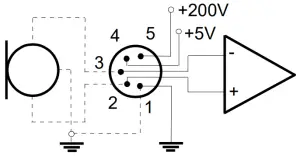
1 XLR input connectorThe 5-pole XLR input connector represents the analog inputs of the recording device and provide power supply voltages for external amplifiers and microphones. The connector scheme is as follows:
- Ground
- Positive input
- Negative input
- +5V supply voltage (max current 20 mA)
- +200V polarization voltage
 differential sourcesingle-ended source
 differential source
2 USB 2.0 interface
3 TRIGGER input/outputThis 2-pole (mono) 2.5 mm mini-jack connector is electrically connected to the TRG button (7) and allows connecting an external trigger. This input is TTL-compatible (there is additionally an internal pull-up resistor of 10 kOhm to Vcc). Pulling this input to ground (for instance by closing a simple switch) will activate the logic USG TRG button.
See the TRG out mode section on the last page on how to congigure this TRIGGER socket as an output.
For a reliable electrical connection, a Switchcraft 0.01″ Micro Plug (part number 850X) is recommended.
4 DINThis 2-pole 2.5mm mini-jack connector allows to connect an external digital signal. The input is TTL-compatible (internal pull-up resistor of 10 kOhm to Vcc). The status of this signal is stored in the LSB (bit 0) of the 16-bit data words that are transmitted over the USB and can be used as a sample-precise trigger source in the RECORDER software. It can be extracted afterwards by the Avisoft-SASLab Pro sound analysis software (e.g. for creating labels). The digital input functionality is not available in the 8-bit recording mode.
5 PHONESThis stereo 3.5mm mini jack connector allows to connect headphones or a small speaker for acoustically monitoring the incoming ultrasounds. A undersampling technique is being used to convert the ultrasonic sounds into audible signals. The undersampling ratio can be adjusted from the Advanced USGH Settings dialog box of the RECORDER USGH software (see section RECORDER USGH Settings for details).
6 SYNC input/outputThis socket allows to synchronize the sample clock signals of several UltraSoundGate units. To accomplish this, all devices must be connected to a single computer and one device must be configured as the master (see section RECORDER USGH Settings for details on this).
7 TRG buttonThis button can control the .wav file recording process in the RECORDER software. To enable this mode of operation, one of the following Trigger source options must be selected from the configuration dialog box:USG TRG button auto hold : Pressing the button for more than 2 seconds will activate an auto hold mechanism (the recording continues after releasing the button and will stop once the button is pressed again). If the button is pressed for less than two seconds, it will only record as long as the button is being pressed. USG TRG button : The software will record as long as the button is pressed. USG TRG button inversed : The software will record as long as the button is not pressed (or as long as the external TRG signal is not active (logic high)). USG TRG button toggled : The software will start recording once the button is pressed and continues until the button is pressed again.
8 REC indicatorThis amber colored LED will flash once the device is connected to the PC. It will be switched off once the RECORDER USGH software is running in the monitoring mode. In this mode, the REC LED indicates whether the RECORDER software is recording the incoming data onto disk.
9 OVERload indicatorThe red OVER LED indicates clipping (over-modulation). If this happens, the gain should be reduced by turning the gain control knob to the left.
10 POWER indicatorThis green LED indicates that the unit is connected to the USB power supply.
11 GAIN control knobThis control knob adjusts the analog input recording level.
12 VOLUME control knobThis knob adjusts the volume of the phones monitor output (5).
RECORDER USGH Settings
The configuration dialog box can be launched from the menu Options/Configuration… or through the button ![]()
 The input sample rate can be selected from the Input Device Settings section. Available sample rates are 1000, 750, 666, 500, 375, 400, 333, 300, 250, 214, 200, 187, 166, 150, 125, 100, 75, 62 and 50 kHz.
The Buffer setting determines the USB transfer buffer size on the PC. Shorter durations will provide low real-time spectrogram display latencies but might lead to erroneous USB transfers under certain conditions.
The Settings… button in the Input Device Settings section launches the Advanced USGH Device Settings dialog box that provides several additional device-specific options:
Enable master/slave mode for synchronizing several devices If you use more than one UltraSoundGate XX16H device, it is possible to synchronize their A/D converter sampling clock signals by connecting them through the SYNC sockets and activating this option (a 3 pole cable fitted with 3.5mm phone plugs is required). In such a set-up, one device acts as the clock master and the other devices listen to the clock signal as slaves.
Activate slave mode for this device In the master/slave mode, one devices acts as the master and the others as slaves. So, this option must be disabled on the unit that should act as the master and must enabled on all other slave units (all USG XX16H devices can act either as slave or master).
Enable low power mode The A/D converter chips can optionally be operated in a power-saving mode that would increase the battery life in mobile laptop-based systems. The low-power mode slightly degrades the dynamic range performance. This option should also be activated if the USG 1216H is bus-powered from a single USB port only. Otherwise, the supply voltage might drop below a critical value, which can prevent the proper operation of the A/D converters.
Enable band-pass mode At a few sample rates (50, 62.5, 75, 150, 187.5, 200, 250, 333 and 375 kHz), the A/D converter can be configured for a special band-pass mode in which the analog input bandwidth ranges from fs/2 to fs instead of the normal mode from 0 to fs/2. This option can be advantageous for monitoring applications that require minimal .WAV files sizes. Note that the frequency scale of the resulting .WAV files will be reversed.
Turn on the polarization voltage This option activates the internal 200V polarization voltage generator of the UltraSoundGate XX16H devices and must be activated when using the CM16/CMPA microphones.
Ignore GetOverlappedResult error By default, the GetOverlapped Result error message will stop the monitoring/recording process. If this option is activated, the monitoring procedure will be immediately restarted, which is desired in long-term monitoring applications.
TRG out mode This option allows to change the I/O direction of the TRG socket. If activated, the TRG socket will be configured as a digital output that carries the state of the internal trigger or file saving state as selected from the Control Output settings dialog box (Ctrl Out… button). In this case, the USG TRG button trigger source options will not work. The TRG out mode option is only available on units that have the firmware version 1.1 or higher.
Monitor undersampling ratio This list box allows to select the desired undersampling ratio of the acoustic monitoring output (5) from 2 to 30 in steps of two. The internal D/A converter will be clocked at a rate that is equal to the selected input (A/D converter) sample rate divided by the selected ratio. The resulting output sample rate is displayed behind the ratio (= xxx Hz). For instance, if you have selected an input sample rate of 333333 Hz and an undersampling ratio of 10:1, the resulting output sample rate will be 33333 Hz. All input signal components above the Nyquist frequency (half of the output sample rate = 16666 Hz) will be folded down to the range between zero and the Nyquist frequency. For instance, a 30 kHz input signal will appear at the monitor output at a frequency of 3333 Hz.
Sound-activated recording can be arranged by selecting the Trigger source option level of this channel. For remote-controlled triggering via the trigger button on the device or via the external TRG input, one of the trigger options USG TRG button… can be used. For triggering by a TTL signal attached to DIN, select UltraSoundGate DI.
The Pre-trigger duration should be kept as short as possible. Long pre-trigger settings can lead to data transmission errors if the sample rate and the number of channels is high.
In order to simplify the operation of the Avisoft-RECORDER software in the field, a link to RECORDER USGH may be added to the Windows Startup folder (Start->All Programs->Startup). Additionally, the Avisoft-RECORDER option Monitoring/Autostart should be activated. This arrangement will start the monitoring process automatically after booting the laptop (the UltraSoundGate device must be attached to the USB port prior to booting Windows).
Please refer to the users guide or the online help system for further details on the Avisoft-RECORDER software.
End-user Agreement
This a legal agreement between Avisoft Bioacoustics and the buyer. By operating this device and the accompanying software, the buyer accepts the terms of this agreement.
- The Device and the accompanying software is warranted to perform substantially in accordance with the operating manual for a period of 24 months from the date of shipment.
- EXCEPT AS SET FORTH IN THE EXPRESS WARRANTY ABOVE, THE DEVICE IS PROVIDED WITH NO OTHER WARRANTIES, EXPRESS OR IMPLIED. THE VENDOR EXCLUDES ALL IMPLIED WARRANTIES, INCLUDING, BUT NOT LIMITED TO, IMPLIED WARRANTIES OF MERCHANTIBILITY AND FITNESS FOR A PARTICULAR PURPOSE.
- The Vendor’s entire liability and the Buyer’s exclusive remedy shall be, at the Vendor’s SOLE DISCRETION, either (1) return of the device and refund of purchase price or (2) repair or replacement of the device.
- THE VENDOR WILL NOT BE LIABLE FOR ANY SPECIAL, INDIRECT, OR CONSEQUENTIAL DAMAGES HEREUNDER, INCLUDING, BUT NOT LIMITED TO, LOSS OF PROFITS, LOSS OF USE, OR LOSS OF DATA OR INFORMATION OF ANY KIND, ARISING OUT OF THE USE OF OR INABILITY TO USE THE DEVICE IN NO EVENT SHALL THE VENDOR BE LIABLE FOR ANY AMOUNT IN EXCESS OF THE PURCHASE PRICE.
- This agreement is the complete and exclusive agreement between the Vendor and the Buyer concerning the device.
Avisoft Bioacoustics e.K. Goethestr. 47 16548 Glienicke/Nordbahn Germany
Phone: +49 (0)33056 426086Fax: +49 (0)33056 426087
www.avisoft.comwww.ultrasoundgate.com
report this ad![]()
References
[xyz-ips snippet=”download-snippet”]