AXIS Network Camera User Manual

Product overview
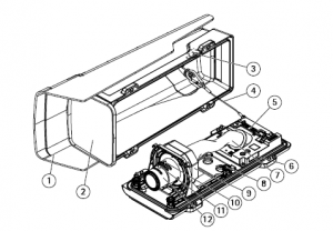
- Weather shield
- Window
- Intrusion alarm magnet
- Safety wire
- IK10 tool
- Intrusion alarm sensor
- Cable cover
- Spring loaded thumb screw (4x)
- Optic unit
- Zoom puller
- Lock screw for focus ring
- Focus ring
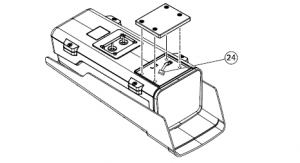
Product overview
- I/O connector
- RS485/422 connector
- Power connector
- Network connector (PoE)
- microSD card slot
- Audio in
- Audio out
- Control button
- Status LED
- Cable gasket M20 (2x)
- Iris connector
- Illuminator connector

Find the device on the network
To find Axis devices on the network and assign them IP addresses in Windows®, use AXIS IP Utility or AXIS Device Manager. Both applications are free and can be downloaded from axis.com/support For more information about how to find and assign IP addresses, see the document How to assign an IP address and access your device on the device page at axis.com
Access the device
- Open a browser and enter the IP address or host name of the Axis device. If you have a Mac computer (OS X), go to Safari, click on Bonjour and select the device from the drop-down list. To add Bonjour as a browser bookmark, go to Safari > Preferences. If you do not know the IP address, use AXIS IP Utility or AXIS Device Manager to find the device on the network.
- Enter the username and password. If you access the device for the first time, you must set the root password. See Set a secure password for the root account on page 5 .
- The live view page opens in your browser.
Verify that no one has tampered with the firmware
To make sure that the device has its original Axis firmware, or to take full control of the device after a security attack:
- Reset to factory default settings. See Reset to factory default settings on page 15 After the reset, secure boot guarantees the state of the device.
- Configure and install the device.
About secure passwords
ImportantAxis devices send the initially set password in clear text over the network. To protect your device after the first login, set up a secure and encrypted HTTPS connection and then change the password. The device password is the primary protection for your data and services. Axis devices do not impose a password policy as they may be used in various types of installations.To protect your data we strongly recommend that you:
- Use a password with at least 8 characters, preferably created by a password generator.
- Don’t expose the password.
- Change the password at a recurring interval, at least once a year.
Set a secure password for the root account
ImportantThe default administrator username is root. If the password for root is lost, reset the device to factory default settings.
- Type a password. Follow the instructions about secure passwords. See About secure passwords on page 5 .
- Retype the password to confirm the spelling.
- Click Create login. The password has now been configured.
Setup
About the product’s built-in help
You can access the built-in help from the product’s webpage. The help provides more detailed information on the product’s features and their settings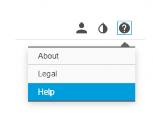
Replace the lens
- Stop all recordings and disconnect power from the product.
- Disconnect the lens cable and remove the standard lens.
- Attach the new lens and connect the lens cable.
- Reconnect the power.
- Log in to the product’s webpage, go to the Image tab and then select the P-Iris lens you have installed.Note If you use a DC iris lens, select Generic DC Iris.
- For the changes to take effect, you need to restart the device. Go to System > Maintenance and click Restart.
- Adjust the zoom and focus.
- Loosen the four spring loaded thumb screws.
- Use the IK10 tool to set the distance between the window and the lens.
- Tighten the four thumb screws.

Hide parts of the image with privacy masks
What is a privacy mask?
A privacy mask is a user-defined area that covers a part of the monitored area. In the video stream, privacy masks appear either as blocks of solid color or with a mosaic pattern.You’ll see the privacy mask on all snapshots, recorded video, and live streams. You can use the VAPIX® application programming interface (API) to turn off the privacy masks.
Important
Using multiple privacy masks may affect the product’s performance. Create a privacy mask To create a privacy mask, go to Settings > Privacy mask .
Select exposure mode
There are different exposure mode options in the camera that adjusts aperture, shutter speed, and gain to improve image quality for specific surveillance scenes. Go to Settings > Image > Exposure and select between the following exposure modes:
- For most use cases, select Automatic exposure.
- For environments with certain artificial lighting, for example fluorescent lighting, select Flicker-free. Select the same frequency as the power line frequency.
- For environments with certain artificial light and bright light, for example outdoors with fluorescent lighting at night and sun during daytime, select Flicker-reduced. Select the same frequency as the power line frequency.
Maximize details in an image
ImportantIf you maximize details in an image, the bitrate will probably increase and you might get a reduced frame rate.
- Set the compression as low as possible.
- Select MJPEG streaming.
- Turn off Zipstream functionality.
Monitor long and narrow areasUse corridor format to better utilize the full field of view in a long and narrow area, for example a staircase, hallway, road, or tunnel.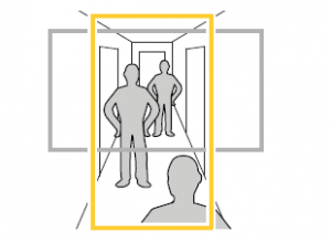
- Depending on your product, turn the camera or the 3-axis lens in the camera 90° or 270°.Find out more at axis.com/axis-corridor-format
Improve license plate recognition
To better recognize the license plate of a car passing by the camera, you can apply and adjust a number of things.One option is to use the pixel counter in your camera to set the optimal pixel resolution:
- Go to Settings > System > Orientation and click
- Adjust the size and placement of the rectangle in the camera’s live view around the area of interest, for example where the license plates of passing cars are expected to appear. You can then see the number of pixels represented by the sides of the rectangle
NoteYou can use an object of a known size in the view as a reference to decide how much resolution is needed for recognition. In addition, you can try to adjust the following to optimize license plate recognition:
- Shutter speed
- Gain
- Zoom
About view area
A view area is a cropped part of the full view. You can stream and store view areas instead of the full view to minimize bandwidth and storage needs. If you enable PTZ for a view area, you can pan, tilt and zoom within it. By using view areas you can remove parts of the full view, for example, the sky. When you set up a view area, we recommend you to set the video stream resolution to the same size as or smaller than the view area size. If you set the video stream resolution larger than the view area size it implies digitally scaled up video after sensor capture,which requires more bandwidth without adding image information.
Handle scenes with strong backlightDynamic range is the difference in light levels in an image. In some cases the difference between the darkest and the brightest areas can be significant. The result is often an image where either the dark or the bright areas are visible. Wide dynamic range (WDR) makes both dark and bright areas of the image visible.
- Go to Settings > Image.
- If required, turn on WDR under Wide dynamic range.
- Use the Local contrast slider to adjust the amount of WDR.

NoteWDR may cause artifacts in the image. Find out more about WDR and how to use it at axis.com/web-articles/wdr
About overlays
Overlays are superimposed over the video stream. They are used to provide extra information during recordings, such as a timestamp,or during product installation and configuration.
Make the camera show a text overlay when it detects motion
This example explains how to display the text “Motion detected” when the camera detects motion: Make sure the AXIS Video Motion Detection application is running:
- Go to Settings > Apps > AXIS Video Motion Detection.
- Start the application if it is not already running.
- Make sure you have set up the application according to your needs.Add the overlay text:
- Go to Settings > Overlay.
- Select Create overlay and select Text overlay.
- Enter #D in the text field.
- Choose text size and appearance.
- To position the text overlay, choose Custom or one of the presets.Create an action rule:
- Go to System > Events > Action rules.
- Create an action rule with AXIS Video Motion Detection as trigger.
- From the list of actions, select Overlay text.
- Type “Motion detected”.
- Set the duration.
NoteIf you update the overlay text it will be automatically updated on all video streams dynamically
Choose video compression formatDecide which compression method to use based on your viewing requirements, and on the properties of your network. Theavailable options are: Motion JPEGNoteTo ensure support for the Opus audio codec, the Motion JPEG stream is always sent over RTP. Motion JPEG or MJPEG is a digital video sequence that is made up of a series of individual JPEG images. These images are then displayed and updated at a rate sufficient to create a stream that shows constantly updated motion. For the viewer to perceive motionvideo the rate must be at least 16 image frames per second. Full motion video is perceived at 30 (NTSC) or 25 (PAL) frames per second. The Motion JPEG stream uses considerable amounts of bandwidth, but provides excellent image quality and access to every image contained in the stream. H.264 or MPEG-4 Part 10/AVCNoteH.264 is a licensed technology. The Axis product includes one H.264 viewing client license. Installing additional unlicensed copies of the client is prohibited. To purchase additional licenses, contact your Axis reseller. H.264 can, without compromising image quality, reduce the size of a digital video file by more than 80% compared to the Motion JPEG format and by as much as 50% compared to the MPEG-4 standard. This means that less network bandwidth and storage space are required for a video file. Or seen another way, higher video quality can be achieved for a given bitrate. H.265 or MPEG-H Part 2/HEVCNoteH.265 is licensed technology. The Axis product includes one H.265 viewing client license. Installing additional unlicensed copies of the client is prohibited. To purchase additional licenses, contact your Axis reseller.
Reduce bandwidth and storage
ImportantIf you reduce the bandwidth it can result in loss of details in the picture.
- Go to live view and select H.264.
- Go to Settings > Stream.
- Do one or more of the following:– Turn on the Zipstream functionality and select the desired level.NoteThe zipstream settings are used for both H.264 and H.265.– Turn on dynamic GOP and set a high GOP length value.– Increase the compression.– Turn on dynamic FPS.
NoteWeb browsers do not support H.265 decoding. Use a video management system or application supporting H.265 decoding.
Set up network storage
To store recordings on the network, you need to set up network storage:
- Go to Settings > System > Storage.
- Click Setup under Network storage.
- Enter the IP address of the host server.
- Enter the name of the shared location on the host server.
- Move the switch if the share requires a login, and enter username and password.
- Click Connect
Add audio to your recording
Edit the stream profile which is used for the recording:
- Go to Settings > System > Stream profiles.
- Select the stream profile and click Modify.
- In the Audio tab, select the Audio stream checkbox and select On from the drop-down list.
- Click Ok.
Record and watch video
To record video you must first set up network storage, see Set up network storage on page 13, or have an SD card installed.
- Go to the camera’s live view.
- Click on Record once to start recording and one more time to stop recording.To watch your recording:
- Click on Storage > Go to recordings.
- Select your recording in the list and it will play automatically.
Rules and alerts
You can create rules to make your device perform an action when certain events occur. A rule consists of conditions and actions. The conditions can be used to trigger the actions. For example, the device can start a recording or send an email when it detects motion, or show an overlay text when it records.
Trigger an action
- Go to Settings > System > Events to set up an action rule. The action rule defines when the camera will perform certain actions. Action rules can be setup as scheduled, recurring, or for example, triggered by motion detection.
- Select what Trigger must be met to trigger the action. If you specify more than one trigger for the action rule, all of them must be met to trigger the action.
- Select which Action the camera should perform when the conditions are met.NoteIf you make changes to an active action rule, the action rule needs to be restarted for the changes to take effect.
Record video when the camera detects motion
This example explains how to set up the camera to start recording to the SD card five seconds before it detects motion and tob stop one minute after.Make sure the AXIS Video Motion Detection application is running:
- Go to Settings > Apps > AXIS Video Motion Detection.
- Start the application if it is not already running.
- Make sure you have set up the application according to your needs.Create an action rule:
- Go to Settings > System > Events and add an action rule.
- Type a name for the action rule.
- From the list of triggers, select Applications and then select AXIS Video Motion Detection (VMD).
- From the list of actions, select Record video.
- Select an existing stream profile or create a new one.
- Enable and set the pre-trigger time to 5 seconds.
- Enable While the rule is active.
- Enable and set the post-trigger time to 60 seconds.
- Select SD card from the list of storage options.
- Click Ok.
Applications
AXIS Camera Application Platform (ACAP) is an open platform that enables third parties to develop analytics and other applications for Axis products. To find out more about available applications, downloads, trials and licenses, go to axis.com/applications To find the user manuals for Axis applications, go to axis.comNote
- Several applications can run at the same time but some applications might not be compatible with each other. Certain combinations of applications might require too much processing power or memory resources when run in parallel. Verify that the applications work together before deployment.
Troubleshooting
If you can’t find what you’re looking for here, try the troubleshooting section at axis.com/support
Reset to factory default settings
ImportantReset to factory default should be used with caution. A reset to factory default resets all settings, including the IP address, to the factory default values.To reset the product to the factory default settings:
- Disconnect power from the product.
- Press and hold the control button while reconnecting power. See Product overview on page 3 .
- Keep the control button pressed for 15–30 seconds until the status LED indicator flashes amber.
- Release the control button. The process is complete when the status LED indicator turns green. The product has been reset to the factory default settings. If no DHCP server is available on the network, the default IP address is 192.168.0.90
- Use the installation and management software tools to assign an IP address, set the password, and access the video stream. The installation and management software tools are available from the support pages on axis.com/support It is also possible to reset parameters to factory default through the web interface. Go to Settings > System > Maintenance and click Default.
Firmware options
Axis offers product firmware management according to either the active track or the long-term support (LTS) tracks. Being on the active track means continuously getting access to all the latest product features, while the LTS tracks provide a fixed platform with periodic releases focused mainly on bug fixes and security updates.Using firmware from the active track is recommended if you want to access the newest features, or if you use Axis end-to-end system offerings. The LTS tracks are recommended if you use third-party integrations, which are not continuously validated against the latest active track. With LTS, the products can maintain cybersecurity without introducing any significant functional changes or affecting any existing integrations. For more detailed information about Axis product firmware strategy, go to axis.com/support/firmware
Check the current firmware
Firmware is the software that determines the functionality of network devices. One of your first actions when troubleshooting a problem should be to check the current firmware version. The latest version may contain a correction that fixes your particular problem.
To check the current firmware:
- Go to the product’s webpage.
- Click on the help menu.
- Click About.
Upgrade the firmware
ImportantPreconfigured and customized settings are saved when the firmware is upgraded (provided that the features are available inthe new firmware) although this is not guaranteed by Axis Communications AB.ImportantMake sure the product remains connected to the power source throughout the upgrade process.NoteWhen you upgrade the product with the latest firmware in the active track, the product receives the latest functionality available. Always read the upgrade instructions and release notes available with each new release before upgrading the firmware. To find the latest firmware and the release notes, go to axis.com/support/firmware
- Download the firmware file to your computer, available free of charge at axis.com/support/firmware
- Log in to the product as an administrator.
- Go to Settings > System > Maintenance. Follow the instructions on the page. When the upgrade has finished, the product restarts automatically.
AXIS Device Manager can be used for multiple upgrades. Find out more at axis.com/products/axis-device-manager
Technical issues, clues and solutions
If you can’t find what you’re looking for here, try the troubleshooting section at axis.com/supportProblems upgrading the firmwareFirmware upgrade failure If the firmware upgrade fails, the device reloads the previous firmware. The most common reasonis that the wrong firmware file has been uploaded. Check that the name of the firmware filecorresponds to your device and try again.Problems after firmwareupgradeIf you experience problems after a firmware upgrade, roll back to the previously installed versionfrom the Maintenance page.Problems setting the IP addressThe device is located on adifferent subnetIf the IP address intended for the device and the IP address of the computer used to access thedevice are located on different subnets, you cannot set the IP address. Contact your networkadministrator to obtain an IP address.The IP address is being usedby another deviceDisconnect the Axis device from the network. Run the ping command (in a Command/DOS window,type ping and the IP address of the device):
- If you receive: Reply from <IP address>: bytes=32; time=10… this means that the IP address may already be in use by another device on the network.Obtain a new IP address from the network administrator and reinstall the device.
- If you receive: Request timed out, this means that the IP address is available for use with the Axis device. Check all cabling and reinstall the device.Possible IP address conflict with another device on the same subnetThe static IP address in the Axis device is used before the DHCP server sets a dynamic address.This means that if the same default static IP address is also used by another device, there maybe problems accessing the device
The device cannot be accessed from a browser
Cannot log in When HTTPS is enabled, ensure that the correct protocol (HTTP or HTTPS) is used when attemptingto log in. You may need to manually type http or https in the browser’s address field.If the password for the user root is lost, the device must be reset to the factory default settings.See Reset to factory default settings on page 15.The IP address has beenchanged by DHCPIP addresses obtained from a DHCP server are dynamic and may change. If the IP address has beenchanged, use AXIS IP Utility or AXIS Device Manager to locate the device on the network. Identifythe device using its model or serial number, or by the DNS name (if the name has been configured).If required, a static IP address can be assigned manually. For instructions, go to axis.com/supportCertificate error when usingIEEE 802.1XFor authentication to work properly, the date and time settings in the Axis device must besynchronized with an NTP server. Go to Settings > System > Date and timeThe device is accessible locally but not externallyTo access the device externally, we recommend using one of the following applications for Windows®:
- AXIS Companion: free of charge, ideal for small systems with basic surveillance needs.
- AXIS Camera Station: 30-day trial version free of charge, ideal for small to mid-size systems.For instructions and download, go to axis.com/products/axis-companionProblems with streamingMulticast H.264 onlyaccessible by local clientsCheck if your router supports multicasting, or if the router settings between the client and thedevice need to be configured. The TTL (Time To Live) value may need to be increased.No multicast H.264displayed in the clientCheck with your network administrator that the multicast addresses used by the Axis deviceare valid for your network.Check with your network administrator to see if there is a firewall preventing viewing.Poor rendering of H.264 imagesEnsure that your graphics card is using the latest driver. The latest drivers can usually bedownloaded from the manufacturer’s website.Color saturation is differentin H.264 and Motion JPEGModify the settings for your graphics adapter. Go to the adapter’s documentation for moreinformation.Lower frame rate thanexpected
- See Performance considerations on page 17.
- Reduce the number of applications running on the client computer.
- Limit the number of simultaneous viewers.
- Check with the network administrator that there is enough bandwidth available.
- Lower the image resolution.
- The maximum frames per second is dependent on the utility frequency (60/50 Hz)of the Axis device.Can’t select H.265 encodingin live viewWeb browsers do not support H.265 decoding. Use a video management system or applicationsupporting H.265 decoding.
Performance considerations
When setting up your system, it is important to consider how various settings and situations affect the performance. Some factors affect the amount of bandwidth (the bitrate) required, others can affect the frame rate, and some affect both. If the load on the CPU reaches its maximum, this also affects the frame rate. The following factors are the most important to consider:
- High image resolution or lower compression levels result in images containing more data which in turn affects the bandwidth.
Troubleshooting
- Rotating the lens manually will result in better performance compared to rotating the image from the GUI.
- Access by large numbers of Motion JPEG or unicast H.264 clients affects the bandwidth.
- Simultaneous viewing of different streams (resolution, compression) by different clients affects both frame rate and bandwidth. Use identical streams wherever possible to maintain a high frame rate. Stream profiles can be used to ensure that streams are identical.
- Accessing Motion JPEG and H.264 video streams simultaneously affects both frame rate and bandwidth.
- Heavy usage of event settings affects the product’s CPU load which in turn affects the frame rate.
- Using HTTPS may reduce frame rate, in particular if streaming Motion JPEG.
- Heavy network utilization due to poor infrastructure affects the bandwidth.
- Viewing on poorly performing client computers lowers perceived performance and affects frame rate.
- Running multiple AXIS Camera Application Platform (ACAP) applications simultaneously may affect the frame rate and the general performance
Specifications
To find the latest version of the product’s datasheet, go to the product page at axis.com and locate Support & Documentation.LED IndicatorsNote
- The Status LED can be configured to be unlit during normal operation. To configure, go to Settings > System > Plain config. See the online help for more information.
- The Status LED can be configured to flash while an event is active.
- The Status LED can be configured to flash for identifying the unit. Go to Settings > System > Plain config.
- The LEDs turn off when you close the casing
| Status LED | Indication |
| Unlit | Connection and normal operation. |
| Green | Steady green for 10 seconds for normal operation after startup completed. |
| Amber | Steady during startup. Flashes during firmware upgrade or reset to factory default. |
| Amber/Red | Flashes amber/red if network connection is unavailable or lost. |
| Red | Firmware upgrade failure. |
| Network LED | Indication |
| Green | Steady for connection to a 1 Gbit/s network. Flashes for network activity. |
| Amber | Steady for connection to a 10/100 Mbit/s network. Flashes for network activity. |
| Unlit | No network connection. |
Status LED behavior for focus assistant
NoteOnly valid for optional P-iris, DC-iris or manual iris lenses.The status LED flashes when the Focus Assistant is active.
| Color | Indication |
| Red | The image is out of focus.
Adjust the lens. |
| Amber | The image is close to focus. The lens needs fine tuning. |
| Green | The image is in focus. |
SD card slot
NOTICE
- Risk of damage to SD card. Do not use sharp tools, metal objects, or excessive force when inserting or removing the SD card. Use your fingers to insert and remove the card.
- Risk of data loss and corrupted recordings. Do not remove the SD card while the product is running. Unmount the SD card from the product’s webpage before removal
Specifications
This product supports microSD/microSDHC/microSDXC cards. For SD card recommendations, see axis.com microSD, microSDHC, and microSDXC Logos are trademarks of SD-3C LLC. microSD, microSDHC, microSDXC are trademarks or registered trademarks of SD-3C, LLC in the United States, other countries or both.
Buttons Control buttonThe control button is used for:
- Enabling the Focus Assistant. Press and very quickly release the Control button.
- Resetting the product to factory default settings. See Reset to factory default settings on page 15.
- Connecting to an AXIS Video Hosting System service. To connect, press and hold the button for about 3 seconds until the status LED flashes green.
Connectors Network connector
RJ45 Ethernet connector with Power over Ethernet (PoE).Audio connectorThe Axis product has the following audio connectors:
- Audio in – 3.5 mm input for a mono microphone, or a line-in mono signal (left channel is used from a stereo signal).
- Audio out – 3.5 mm output for audio (line level) that can be connected to a public address (PA) system or an active speaker with a built-in amplifier. A stereo connector must be used for audio out

3.5 mm audio connectors (stereo)
| 1 Tip | 2 Ring | 3 Sleeve | |
| Audio Input | Microphone/Line in | Ground | |
| Audio Output | Line out (mono) | Ground |
Illuminator connector
4-pin connector used to connect AXIS Fixed Box Illuminator Kit A to the camera.
I/O connector
Use the I/O connector with external devices in combination with, for example, motion detection, event triggering, and alarm notifications. In addition to the 0 V DC reference point and power (DC output), the I/O connector provides the interface to: Digital input – For connecting devices that can toggle between an open and closed circuit, for example PIR sensors, door/window contacts, and glass break detectors. Supervised input – Enables possibility to detect tampering on a digital input.
Digital output – For connecting external devices such as relays and LEDs. Connected devices can be activated by the VAPIX® Application Programming Interface or from the product’swebpage
| Function | Pin | Notes | Specifications |
| DC ground | 1 | 0 V DC | |
| DC output | 2 | Can be used to power auxiliary equipment. Note: This pin can only be used as power out. | 12 V DC
Max load = 50 mA |
| Input 1 | 3 | Digital input or Supervised input – Connect to pin 1 to activate, or leave floating (unconnected) to deactivate. To use supervised input, install end-of-line resistors. See connection diagram for information about how to connect the resistors. | 0 to max 30 V DC |
| Output 1 | 4 | Digital output – Internally connected to pin 1 (DC ground) when active, and floating (unconnected) when inactive. If used with an inductive load, e.g., a relay, connect a diode in parallel with the load, to protect against voltage transients. | 0 to max 30 V DC, open drain, 100 mA |
| Input 2 | 5 | Digital input or Supervised input – Connect to pin 1 to activate, or leave floating (unconnected) to deactivate. To use supervised input, install end-of-line resistors. See connection diagram for information about how to connect the resistors. | 0 to max 30 V DC |
| Output 2 | 6 | Digital output – Internally connected to pin 1 (DC ground) when active, and floating (unconnected) when inactive. If used with an inductive load, e.g., a relay, connect a diode in parallel with the load, to protect against voltage transients. | 0 to max 30 V DC, open drain, 100 mA |
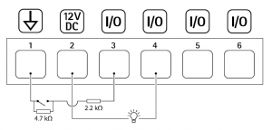
- DC ground
- DC output 12 V, max 50 mA
- Supervised input port 1
- Digital output port 1
- Supervised input port 2
- Digital output port 2
Power connector2-pin terminal block for DC power input. Use a Safety Extra Low Voltage (SELV) compliant limited power source (LPS) with eithera rated output power limited to ≤100 W or a rated output current limited to ≤5 A.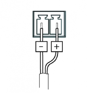
RS485/RS422 connectorTwo 2-pin terminal blocks for RS485/RS422 serial interface used to control auxiliary equipment such as pan-tilt devices. The serial port can be configured to support:
- Two-wire RS485 half duplex
- Four-wire RS485 full duplex
- Two-wire RS422 simplex
- Four-wire RS422 full duplex point to point communication
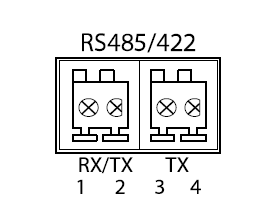
| Function | Pin | Notes |
| RS485B alt RS485/422 RX(B) | 1 | RX pair for all modes (combined RX/TX for 2-wire RS485) |
| RS485A alt RS485/422 RX(A) | 2 | |
| RS485/RS422 TX(B) | 3 | TX pair for RS422 and 4-wire RS485 |
| RS485/RS422 TX(A) | 4 |
ImportantThe maximum cable length is 30 m (98 ft).
Read More About This Manual & Download PDF:
References
Firmware | Axis Communications
Axis Communications – Leader in network cameras and other IP networking solutions | Axis Communications
Welcome to Axis support | Axis Communications
AXIS GENERAL SOFTWARE LICENSE TERMS | Axis Communications
Wide dynamic range | Axis Communications
AXIS Device Manager | Axis Communications
AXIS Companion | Axis Communications
Corridor format | Axis Communications
[xyz-ips snippet=”download-snippet”]