AXIS P14 Network Camera
Series User Manual
![]()
About this manual About this manual
This User Manual provides information on the product regarding:
- Access
- Main use cases
- Troubleshooting
- Specifications
NoteThe User Manual may include more than one product. Part of the content, e.g. some use cases or specifications, may only apply to some of them. For more information on the exact feature set and specifications, see the product’s web page and datasheet at www.axis.com
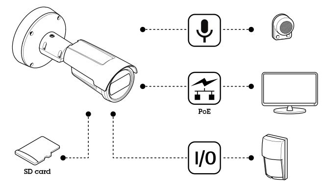
Solution overview
Product overview
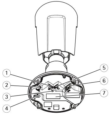
- I/O connector
- Audio connector
- Status LED indicator
- Control button
- microSD card slot
- Network connector
- Part number (P/N) & Serial number (S/N)
Find the device on the network
To find Axis devices on the network and assign them IP addresses in Windows®, use AXIS IP Utility or AXIS Device Manager. Both applications are free and can be downloaded from axis.com/support.
For more information about how to find and assign IP addresses, see the document How to assign an IP address and access your device on the device page at axis.com.
Access the device
- Open a browser and enter the IP address or host name of the Axis device.If you have a Mac computer (OS X), go to Safari, click Bonjour and select the device from the drop-down list. To add Bonjour as a browser bookmark, go to Safari > Preferences. If you do not know the IP address, use AXIS IP Utility or AXIS Device Manager to find the device on the network.
- Enter the username and password. If you access the device for the first time, you must set the root password. See Set a new password for the root account on page 6 .
- The live view page opens in your browser.
Secure passwords
ImportantAxis devices send the initially set password in clear text over the network. To protect your device after the first login, set up a secure and encrypted HTTPS connection and then change the password.
The device password is the primary protection for your data and services. Axis devices do not impose a password policy as they may be used in various types of installations.
To protect your data we strongly recommend that you:
- Use a password with at least 8 characters, preferably created by a password generator.
- Don’t expose the password.
- Change the password at a recurring interval, at least once a year.
Set a new password for the root account
ImportantThe default administrator username is root. If the password for root is lost, reset the device to factory default settings.
- Type a password. Follow the instructions about secure passwords. See Secure passwords on page 6 .
- Retype the password to confirm the spelling.
- Click Create login. The password has now been configured.
Additional settings
Need more help?
You can access the built-in help from the device’s webpage. The help provides more detailed information on the device’s features and their settings.
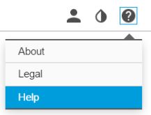
Image quality
Select exposure mode
There are different exposure mode options in the camera that adjusts aperture, shutter speed, and gain to improve image quality for specific surveillance scenes. Go to Settings > Image > Exposure and select between the following exposure modes:
- For most use cases, select Automatic exposure.
- For environments with certain artificial lighting, for example fluorescent lighting, select Flicker-free.
- For environments with certain artificial light and bright light, for example outdoors with fluorescent lighting at night and sun during daytime, select Flicker-reduced.
- To lock the current exposure settings, select Hold current.
View area
A view area is a cropped part of the full view. You can stream and store view areas instead of the full view to minimize bandwidth and storage needs. If you enable PTZ for a view area, you can pan, tilt and zoom within it. By using view areas you can remove parts of the full view, for example, the sky.
When you set up a view area, we recommend you to set the video stream resolution to the same size as or smaller than the view area size. If you set the video stream resolution larger than the view area size it implies digitally scaled up video after sensor capture, which requires more bandwidth without adding image information.
Hide parts of the image with privacy masks
You can create one or several privacy masks to hide parts of the image.
- Go to Settings > Privacy mask.
- Click New.
- Adjust the size, color, and name of the privacy mask according to your needs.
Adjust the focus
- Go to Settings > Image > Focus and click Show AF area.
- Adjust the autofocus area to cover the part of the image that you want to be in focus. If you don’t select an autofocus area, the camera focuses on the entire scene. We recommend that you focus on a static object.
- Click Autofocus. 4. To fine tune the focus, use the focus slider.
Remote focus and zoom
The remote focus and zoom functionality allows you to make focus and zoom adjustments to your camera from a computer. It is a convenient way to ensure that the scene’s focus, viewing angle and resolution are optimized without having to visit the camera’s installation location.
Improve license plate recognition
To better recognize the license plate of a car passing by the camera, you can apply and adjust a number of things. One option is to use the pixel counter in your camera to set the optimal pixel resolution:
- Go to Settings > System > Orientation and click

- Adjust the size and placement of the rectangle in the camera’s live view around the area of interest, for example where the license plates of passing cars are expected to appear. You can then see the number of pixels represented by the sides of the rectangle.
NoteYou can use an object of a known size in the view as a reference to decide how much resolution is needed for recognition.
In addition, you can try to adjust the following to optimize license plate recognition:
- Shutter speed
- Gain
- Zoom
Monitor long and narrow areas
Use corridor format to better utilize the full field of view in a long and narrow area, for example a staircase, hallway, road, or tunnel.
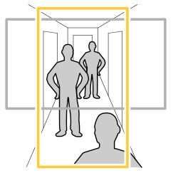
- Depending on your device, turn the camera or the 3-axis lens in the camera 90° or 270°.
- If the device doesn’t rotate the view automatically, log in to the webpage and go to Settings > System > Orientation.
- Click
- Rotate the view 90° or 270°.
Find out more at axis.com/axis-corridor-format.
Reduce noise in low-light conditions
To reduce noise in low-light conditions, you can adjust one or more of the following settings:
- Set the exposure mode to automatic.
NoteA high max shutter value can result in motion blur.
- To slow down the shutter speed, set max shutter to the highest possible value.
- Reduce sharpness in the image.
- Set the max gain to a lower value.
Handle scenes with strong backlight
Dynamic range is the difference in light levels in an image. In some cases the difference between the darkest and the brightest areas can be significant. The result is often an image where either the dark or the bright areas are visible. Wide dynamic range (WDR) makes both dark and bright areas of the image visible.
- Go to Settings > Image > Wide dynamic range.
- If required, turn on WDR.
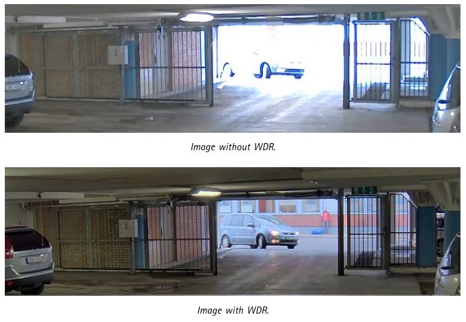 NoteWDR may cause artifacts in the image.
Find out more about WDR and how to use it at axis.com/web-articles/wdr.
Benefit from IR light in low-light conditions using night mode
Your camera uses visible light to deliver color images during the day. As the available light diminishes, you can set the camera to automatically shift to night mode, in which the camera uses both visible light and near-infrared light to deliver black-and-white images. Since the camera uses more of the available light it can deliver brighter, more detailed, images.
- Go to Settings > Image > Day and night, and make sure that the IR cut filter is set to Auto.
- To determine at what light level you want the camera to shift to night mode, move the Threshold slider toward Bright or Dark.
- Enable Allow IR illumination and Synchronize IR illumination to use the camera’s IR light when night mode is activated.
NoteIf you set the shift to night mode to occur when it’s brighter, the image remains sharper as there will be less low-light noise. If you set the shift to occur when it’s darker, the image colors are maintained for longer, but there will be more image blur due to low-light noise.
Maximize details in an image
ImportantIf you maximize details in an image, the bitrate will probably increase and you might get a reduced frame rate.
- Set the compression as low as possible.
- Select MJPEG streaming.
- Turn off Zipstream functionality.
Overlays
Overlays are superimposed over the video stream. They are used to provide extra information during recordings, such as a timestamp, or during product installation and configuration. You can add either text or an image.
Show a text overlay in the video stream when the device detects motion
This example explains how to display the text “Motion detected” when the device detects motion:
Make sure that AXIS Video Motion Detection is running:
- Go to Settings > Apps > AXIS Video Motion Detection.
- Start the application if it is not already running.
- Make sure you have set up the application according to your needs.Add the overlay text:
- Go to Settings > Overlay.
- Enter #D in the text field.
- Choose text size and appearance.Create a rule:
- Go to System > Events > Rules and add a rule
- Type a name for the rule.
- In the list of conditions, select AXIS Video Motion Detection.
- In the list of actions, select Use overlay text.
- Select a view area.
- Type “Motion detected”.
- Set the duration.
- Click Save.
Streaming and storage
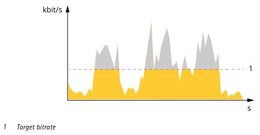
Bitrate control
With bitrate control, you can manage the bandwidth consumption of your video stream.
Variable bitrate (VBR)With variable bitrate, the bandwidth consumption varies based on the level of activity in the scene. The more activity in the scene, the more bandwidth you need. You are guaranteed constant image quality but it requires storage margins.

Maximum bitrate (MBR)With maximum bitrate, you can set a target bitrate to handle bitrate limitations in your system. You may see a decline in image quality or frame rate when the instantaneous bitrate is kept below the specified target bitrate. You can choose to either prioritize image quality or frame rate. We recommend that you configure the target bitrate to a higher value than the expected bitrate. This gives you a margin for additional complexity that needs to be captured.
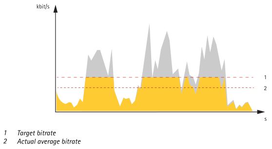
Average bitrate (ABR)With average bitrate, the bitrate is automatically adjusted over a longer timescale. This is so you can meet the specified target and provide the best video quality based on your available storage. Bitrate is higher in scenes with a lot of activity, compared to static scenes. You are more likely to get better image quality when needed when using the average bitrate option. You can define the total storage required to store the video stream for a specified amount of time (retention time) when image quality is adjusted to meet the specified target bitrate. Specify the average bitrate settings in one of the following ways:
- To calculate the estimated storage need, set the target bitrate and the retention time.
- To calculate the average bitrate, based on available storage and required retention time, use the target bitrate calculator.
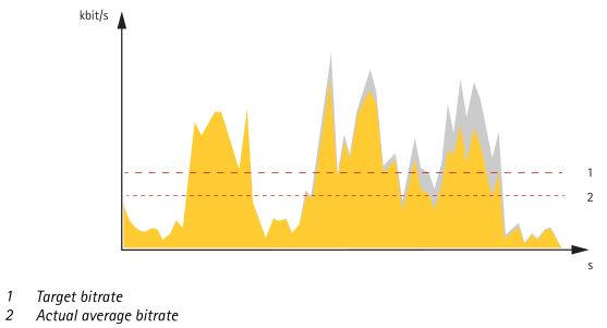
You can also turn on maximum bitrate and specify a target bitrate within the average bitrate option.
Video compression formats
Decide which compression method to use based on your viewing requirements, and on the properties of your network. The available options are:
Motion JPEGMotion JPEG, or MJPEG, is a digital video sequence that is made up of a series of individual JPEG images. These images are then displayed and updated at a rate sufficient to create a stream that shows constantly updated motion. For the viewer to perceive motion video the rate must be at least 16 image frames per second. Full motion video is perceived at 30 (NTSC) or 25 (PAL) frames per second.
The Motion JPEG stream uses considerable amounts of bandwidth, but provides excellent image quality and access to every image contained in the stream.
H.264 or MPEG-4 Part 10/AVC
NoteH.264 is a licensed technology. The Axis product includes one H.264 viewing client license. To install additional unlicensed copies of the client is prohibited. To purchase additional licenses, contact your Axis reseller.
H.264 can, without compromising image quality, reduce the size of a digital video file by more than 80% compared to the Motion JPEG format and by as much as 50% compared to the MPEG-4 standard. This means that less network bandwidth and storage space are required for a video file. Or seen another way, higher video quality can be achieved for a given bitrate.
Reduce bandwidth and storage
ImportantIf you reduce the bandwidth it can result in loss of details in the picture.
- Go to live view and select H.264.
- Go to Settings > Stream.
- Do one or more of the following:
- Turn on the Zipstream functionality and select the desired level.
- Turn on dynamic GOP and set a high GOP length value.
- Increase the compression.
- Turn on dynamic FPS.
Set up network storageTo store recordings on the network, you need to set up network storage:
- Go to Settings > System > Storage.
- Click Setup under Network storage.
- Enter the IP address of the host server.
- Enter the name of the shared location on the host server.
- Move the switch if the share requires a login, and enter username and password.
- Click Connect.
Add audio to your recordingTurn on audio:
1. Go to Settings > Audio and turn on Allow audio.2. Go to Input > Type and select your audio source.
Edit the stream profile which is used for the recording:
3. Go to Settings > Stream and click Stream profiles.4. Select the stream profile and click Audio.5. Select the checkbox and select Include.6. Click Save.7. Click Close.
Events
Set up rules and alertsYou can create rules to make your device perform an action when certain events occur. A rule consists of conditions and actions. The conditions can be used to trigger the actions. For example, the device can start a recording or send an email when it detects motion, or show an overlay text when it records.
Trigger an action
- Go to Settings > System > Events to set up a rule. The rule defines when the camera will perform certain actions. Rules can be setup as scheduled, recurring, or for example, triggered by motion detection.
- Select the Condition that must be met to trigger the action. If you specify more than one condition for the rule, all of the conditions must be met to trigger the action.
- Select which Action the camera should perform when the conditions are met.
NoteIf you make changes to an active rule, then the rule needs to be restarted for the changes to take effect.
Record video when the camera detects motionThis example explains how to set up the camera to start recording to the SD card five seconds before it detects motion and to stop one minute after.
Make sure that AXIS Video Motion Detection is running:
- Go to Settings > Apps > AXIS Video Motion Detection.
- Start the application if it is not already running.
- Make sure you have set up the application according to your needs.
Create a rule:
- Go to Settings > System > Events and add a rule.
- Type a name for the rule.
- In the list of conditions, under Application, select AXIS Video Motion Detection (VMD).
- In the list of actions, under Recordings, select Record video while the rule is active.
- Select an existing stream profile or create a new one.
- Set the prebuffer time to 5 seconds.
- Set the postbuffer time to 60 seconds.
- In the list of storage options, select SD card. 9. Click Save.
Record video when a PIR detector senses motionThis example explains how to connect an Axis PIR detector to the camera, and set up the camera to start recording when the detector senses motion. Required hardware
- 3-wire cable (ground, power, I/O)
- Axis PIR detector
NOTICEDisconnect the camera from power before connecting the wires. Reconnect to power after all connections are done.
Connect the wires to the camera’s I/O connector
NoteFor information on the I/O connector, see Connectors on page 20.
- Connect the ground wire to pin 1 (GND/-).
- Connect the power wire to pin 2 (12V DC output).
- Connect the I/O wire to pin 3 (I/O input).
Connect the wires to the PIR detector’s I/O connector

- Connect the other end of the ground wire to pin 1 (GND/-).
- Connect the other end of the power wire to pin 2 (DC input/+).
- Connect the other end of the I/O wire to pin 3 (I/O output).
Configure the I/O port in the camera’s webpage
- Go to Settings > System > I/O ports.
- Give the input module a descriptive name.
- To make the PIR detector send a signal to the camera when it senses motion, select Closed circuit in the drop-down list.
To trigger the camera to start recording when it receives a signal from the PIR detector, you need to create a rule in the camera’s webpage.
Applications
Applications
AXIS Camera Application Platform (ACAP) is an open platform that enables third parties to develop analytics and other applications for Axis products. To find out more about available applications, downloads, trials and licenses, go to axis.com/applications. To find the user manuals for Axis applications, go to axis.com.
Note· Several applications can run at the same time but some applications might not be compatible with each other. Certain combinations of applications might require too much processing power or memory resources when run in parallel. Verify that the applications work together before deployment.
AXIS People Counter
AXIS People Counter is an analytic application that can be installed on a network camera. The counter is embedded in the camera which means you do not need a dedicated computer to run the application. AXIS People Counter is intended for retail environments, like stores or shopping malls, or other environments where you want to count people.

Troubleshooting
If you can’t find what you’re looking for here, try the troubleshooting section at axis.com/support.
Reset to factory default settings
ImportantReset to factory default should be used with caution. A reset to factory default resets all settings, including the IP address, to the factory default values.
To reset the product to the factory default settings:
- Disconnect power from the product.
- Press and hold the control button while reconnecting power. See Product overview on page 5 .
- Keep the control button pressed for 1530 seconds until the status LED indicator flashes amber.
- Release the control button. The process is complete when the status LED indicator turns green. The product has been reset to the factory default settings. If no DHCP server is available on the network, the default IP address is 192.168.0.90.
- Use the installation and management software tools to assign an IP address, set the password, and access the video stream.
The installation and management software tools are available from the support pages on axis.com/support.
It is also possible to reset parameters to factory default through the web interface. Go to Settings > System > Maintenance and click Default.
Check the current firmware
Firmware is the software that determines the functionality of network devices. One of your first actions when troubleshooting a problem should be to check the current firmware version. The latest version may contain a correction that fixes your particular problem.
To check the current firmware:
- Go to the product’s webpage.
- Click on the help menu .
- Click About.
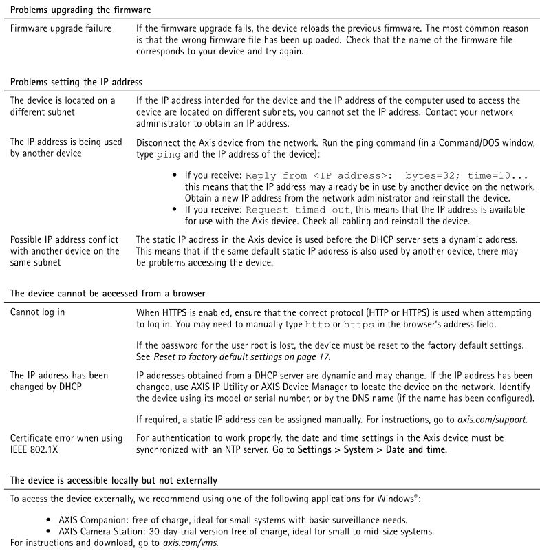
Upgrade the firmware
ImportantPreconfigured and customized settings are saved when the firmware is upgraded (provided that the features are available in the new firmware) although this is not guaranteed by Axis Communications AB.
ImportantMake sure the product remains connected to the power source throughout the upgrade process.
NoteWhen you upgrade the product with the latest firmware in the active track, the product receives the latest functionality available. Always read the upgrade instructions and release notes available with each new release before upgrading the firmware. To find the latest firmware and the release notes, go to axis.com/support/firmware.
- Download the firmware file to your computer, available free of charge at axis.com/support/firmware.
- Log in to the product as an administrator.
- Go to Settings > System > Maintenance. Follow the instructions on the page. When the upgrade has finished, the product restarts automatically.
AXIS Device Manager can be used for multiple upgrades. Find out more at axis.com/products/axis-device-manager.
Technical issues, clues and solutions
If you can’t find what you’re looking for here, try the troubleshooting section at axis.com/support.
Performance considerations
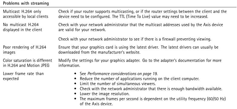 Performance considerations
When setting up your system, it is important to consider how various settings and situations affect the performance. Some factors affect the amount of bandwidth (the bitrate) required, others can affect the frame rate, and some affect both. If the load on the CPU reaches its maximum, this also affects the frame rate.
The following factors are the most important to consider:
- High image resolution or lower compression levels result in images containing more data which in turn affects the bandwidth.
- Rotating the image in the GUI will increase the product’s CPU load.
- Access by large numbers of Motion JPEG or unicast H.264 clients affects the bandwidth.
- Simultaneous viewing of different streams (resolution, compression) by different clients affects both frame rate and bandwidth.
Use identical streams wherever possible to maintain a high frame rate. Stream profiles can be used to ensure that streams are identical.
- Accessing Motion JPEG and H.264 video streams simultaneously affects both frame rate and bandwidth.
- Heavy usage of event settings affects the product’s CPU load which in turn affects the frame rate.
- Using HTTPS may reduce frame rate, in particular if streaming Motion JPEG.
- Heavy network utilization due to poor infrastructure affects the bandwidth.
- Viewing on poorly performing client computers lowers perceived performance and affects frame rate.
- Running multiple AXIS Camera Application Platform (ACAP) applications simultaneously may affect the frame rate and the general performance.
Specifications
To find the latest version of the product’s datasheet, go to the product page at axis.com and locate Support & Documentation.
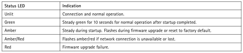
LED Indicators
SD card slot
NOTICE
- Risk of damage to SD card. Do not use sharp tools, metal objects, or excessive force when inserting or removing the SD card. Use your fingers to insert and remove the card.
- Risk of data loss and corrupted recordings. Do not remove the SD card while the product is running. Unmount the SD card from the product’s webpage before removal.
This product supports microSD/microSDHC/microSDXC cards.
For SD card recommendations, see axis.com.
![]() microSD, microSDHC, and microSDXC Logos are trademarks of SD-3C LLC. microSD, microSDHC, microSDXC are trademarks or registered trademarks of SD-3C, LLC in the United States, other countries or both.
microSD, microSDHC, and microSDXC Logos are trademarks of SD-3C LLC. microSD, microSDHC, microSDXC are trademarks or registered trademarks of SD-3C, LLC in the United States, other countries or both.
Control buttonThe control button is used for:
- Resetting the product to factory default settings. See Reset to factory default settings on page 17.
Connectors
Network connectorRJ45 Ethernet connector with Power over Ethernet (PoE).
Audio connector
- Audio in 3.5 mm input for a mono microphone, or a line-in mono signal (left channel is used from a stereo signal).
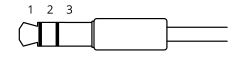
Audio input
For audio in, the left channel is used from a stereo signal.
I/O connector
Use the I/O connector with external devices in combination with, for example, motion detection, event triggering, and alarm notifications. In addition to the 0 V DC reference point and power (DC output), the I/O connector provides the interface to:
Digital input – For connecting devices that can toggle between an open and closed circuit, for example PIR sensors, door/window contacts, and glass break detectors.
Digital output – For connecting external devices such as relays and LEDs. Connected devices can be activated by the VAPIX® Application Programming Interface or from the product’s webpage.
4-pin terminal block


- DC ground
- DC output 12 V, max 25 mA
- Digital input
- Digital output
User ManualAXIS P14 Network Camera Series© Axis Communications AB, 2018 – 2020
Ver. M7.2Date: June 2020Part No. T10116329
References
Wide dynamic range | Axis Communications
AXIS GENERAL SOFTWARE LICENSE TERMS | Axis Communications
Firmware | Axis Communications
Axis Communications – Leader in network cameras and other IP networking solutions | Axis Communications
Welcome to Axis support | Axis Communications
Corridor format | Axis Communications
AXIS Device Manager | Axis Communications
Video management software | Axis Communications
Axis Communications – Leader in network cameras and other IP networking solutions | Axis Communications
[xyz-ips snippet=”download-snippet”]