
![]() AXDIS-LR92INSTALLATION INSTRUCTIONS
AXDIS-LR92INSTALLATION INSTRUCTIONS
Land Rover Range Rover Sport* (with M.O.S.T. 25 amplifier) Data Interface with SWC 2005-2009 †Land Rover Discovery** (with M.O.S.T. 25 amplifier) Data Interface with SWC 2004-2009 †* 1st gen no time retention** No time retention† NAV screen will only show LR logo
INTERFACE FEATURES
- Provides accessory power
- Retains R.A.P. (retained accessory power)
- Designed for amplified models
- Provides NAV outputs (parking brake, reverse, speed sense)
- Retains audio controls on the steering wheel
- Micro-B USB updatable
INTERFACE COMPONENTS
- AXDIS-LR92 harness
- AXDIS-LR92 interface
- AXDIS-LR92 amplifier interface
- AXSWC harness
- AXSWC interface
- Female 3.5mm connector with stripped leads
TOOLS REQUIRED
- Wire cutter
- Crimp tool and connectors (example: butt-connectors, bell caps, etc.)OR
- Solder gun, solder, heat shrink
- Tape
- Zip ties
ATTENTION: With the key out of the ignition, disconnect the negative battery terminal before installing this product. Ensure that all installation connections are secure before cycling the ignition to test this product.NOTE: Refer to the instructions included with the aftermarket radio
CONNECTIONS
From the aftermarket radio to the AXDIS-LR92 harness connect as indicated:
- Orange wire to the illumination wire (if applicable).
- Black wire to the ground wire.
- Yellow wire to the battery wire.
- Red wire to the accessory wire.
- Blue wire to the power antenna turn-on wire.The following (3) wires are only for multimedia/navigation radios that require these wires.
- Blue/Pink wire to the VSS/speed sense wire.
- Green/Purple wire to the reverse wire.
- Light Green wire to the parking brake wire.
- Red and White RCA jacks labeled “FRONT LEFT” and “FRONT RIGHT” to the full range front amplifier output jacks.
- Red and White RCA jacks labeled “AUX Left” and “AUX Right” to the audio AUX-IN jacks. (if applicable)
From the aftermarket radio to the AXSWC harness:This harness is only to be used if the vehicle is equipped with steering wheel controls.
- Connect the Red wire to the accessory wire.3.5mm jack – Steering Wheel Control retention: The 3.5mm jack is to be used to retain audio controls on the steering wheel control.
- For the radios listed below: Connect the female 3.5mm connector with stripped leads to the male 3.5mm SWC jack from the ASWC-1 harness. Tape off and disregard remaining wires.
- Eclipse: Connect the SWC wire, Brown to the Brown/White wire of the connector. Then connect the remaining SWC wire, Brown/White to the Brown wire of the connector.
- Metra OE: Connect the SWC (Key 1) wire Gray to the Brown wire.
- Kenwood or select JVC with a SWC wire: Connect the Blue/Yellow wire to the Brown wire.Note: If the Kenwood radio auto-detects as a JVC, manually set the radio type to Kenwood. See the instructions under Changing Radio Type.
- XITE: Connect the SWC (SWC-2) wire from the radio to the Brown wire.
- Parrot Asteroid Smart or Tablet: Connect the 3.5mm jack into the AX-SWC-PARROT (sold separately), and then connect the 4-pin connector from the AX-SWC-PARROT into the radio.Note: The radio must be updated to rev. 2.1.4 or higher software.
- Universal “2 or 3 wire” radio: Connect the SWC wire, (Key-A or SWC-1) to the Brown wire of the connector. Then connect the remaining SWC wire, (Key-B or SWC-2) to the Brown/White wire of the connector. If the radio comes with a third wire for the ground, disregard this wire.Note: After the interface has been programmed to the vehicle, refer to the manual provided with the radio for assigning the SWC buttons. Contact the radio manufacturer for more information.
- For all other radios: Connect the 3.5mm jack into the port on the radio designated for an external SWC interface. Refer to the manual provided with the radio, if in doubt as to where the 3.5mm jack goes.Adding aftermarket camera:Connect the Yellow female RCA cable from the aftermarket camera to the male RCA video wire.Then plug the Yellow male RCA video wire into the reverse camera input of your aftermarket radio.
INSTALLATION
Installing the AXDIS-LR92 interfaceW ith the key in the off position:
- Connect the AXDIS-LR92 harness to the AXDIS-LR92 interface.
- Connect the AXDIS-LR92 harness to the AXDIS-LR92 amplifier interface.
- Connect the AXSWC harness to the AXSWC interface.
- Connect the AXSWC harness to the AXDIS-LR92 interface.
- Replace the factory circuit board with the AXDIS-LR92 interface and snap it in the factory housing.
- Replace the SWC circuit board with the AXSWC interface and snap it in the factory housing.
- Connect the AXDIS-LR92 harness to the wiring harness in the vehicle.
Installing the Fiber Optic Cable:Removal of the original fiber optic connection is required to adapt to the Media Oriented System Transport (MOST) interface.
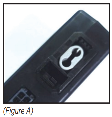
- Seat the AXDIS-LR92 amplifier interface in the black connector housing provided with this kit and snap the housing in place. (Figure A)

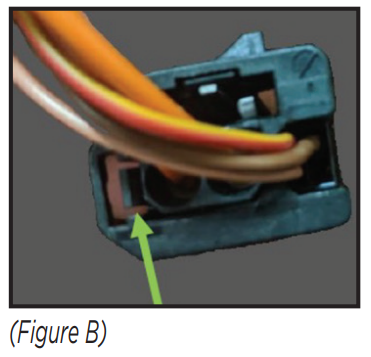
- From the original Fiber Optic Connector: Using a pick tool, carefully pull this tab towards the outside edge for the connector housing. Gently remove the gray fiber optic insert from the connector. (Figure B)
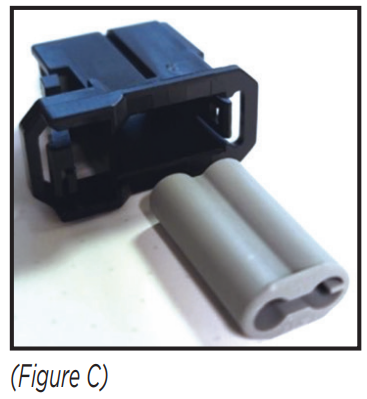
- From the MOST Interface: Push the tab toward the gray dust cover and, using a needle nose plier, remove the gray dust cover. Replace the gray connector with the factory fiber optic cables into the MOST interface’s black connector housing. (Figure C)
PROGRAMMING
Programming the AXSWC Interface
- Open the driver’s door and keep it open throughout the programming process.
- Press and hold the Volume Up button on the steering wheel.
- Turn the ignition on. The L.E.D. in the SWC interface will start flashing rapidly, as the SWC interface searches for the auto manufacturer.
- After a few seconds, the L.E.D. should stop flashing rapidly, then go out for approximately (2) seconds.
- After that (2) seconds there will be a series of (7) Green flashes, some short, and some long. The long flashes represent the wires that are connected from the vehicle to the SWC interface. The 3rd, 4th, 5th, and 6th flashes should be longer.
- The L.E.D. will pause for another (2) seconds, then begin flashing Red (up to 18 times) as the SWC interface locates the aftermarket radio installed. Refer to the L.E.D Feedback Legend for the number of times the light should flash for the radio installed.
- This is the end of the auto-detection stage. If the SWC interface detected the vehicle and radio successfully, the L.E.D. will light up solid red. If not, refer to the troubleshooting documents available at axxessinterfaces.com.
- Release the Volume Up button. Test all functions of the installation for proper operation before reassembling the dash. Refer to the SWC Steering Wheel Control documents available at axxessinterfaces.com for customizing the buttons, if so desired.
PROGRAMMING (CONT.)
L.E.D. FeedbackThe (18) Red L.E.D. flashes represent a different radio manufacturer the SWC interface detects.For example, if you are installing a JVC radio, the SWC interface will flash Red (5) times, then stop. Following is the L.E.D Feedback Legend, which indicates the flash count of the radio manufacturer.
L.E.D. Feedback Legend
| Flash Count | Radio |
| 1 | Eclipse (type 1) t |
| 2 | Kenwood I |
| 3 | Clarion (type 1) t |
| 4 | Sony / Dual |
| 5 | JVC |
| 6 | Pioneer/Jensen |
| 7 | Alpine * |
| 8 | Visteon |
| 9 | Valor |
| 10 | Clarion (type 2) t |
| 11 | Metra OE |
| 12 | Eclipse (type 2) t |
| 13 | LG |
| 14 | Parrot ** |
| 15 | XITE |
| 16 | Philips |
| 17 | TBA |
| 18 | JBL |
Keynotes* If the AXSWC interface flashes Red (7) times, and an Alpine radio is not installed, that means an open connection. Verify that the 3.5mm jack is connected to the correct steering wheel jack/ wire in the radio.** The AX-SWC-PARROT is required (sold separately). Also, the software in the radio must be rev.2.1.4 or higher.† If a Clarion radio is installed and the steering wheel controls do not function, change the radio type to the opposite Clarion radio type; likewise for Eclipse. Refer to the Changing Radio Type document available at axxessinterfaces.com.‡ If a Kenwood radio is installed and the L.E.D. feedback comes back showing as a JVC radio, change the radio type to Kenwood. Refer to the Changing Radio Type document available at axxessinterfaces.com.

Having difficulties? We’re here to help.![]() Contact our Tech Support line at:386-257-1187
Contact our Tech Support line at:386-257-1187 Or via email at:[email protected]Tech Support Hours (Eastern Standard Time)Monday – Friday: 9:00 AM – 7:00 PMSaturday: 10:00 AM – 7:00 PMSunday: 10:00 AM – 4:00 PM
 KNOWLEDGE IS POWER®Enhance your installation and fabrication skills by enrolling in the most recognized and respected mobile electronics school in our industry.Log onto www.installerinstitute.edu or call 386-672-5771 for more information and take steps toward a better tomorrow.
 Metra recommends MECP certified technicians
References
[xyz-ips snippet=”download-snippet”]