AXXESS AXGMMT-01 GM MOST Amplifier Interface 2014-2021 Installation Guide
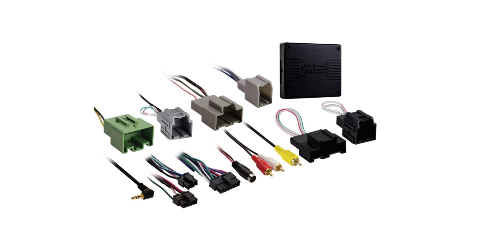
INTERFACE COMPONENTS
- AXGMMT-01 interface
- AXGMMT-01 harness
- 16-pin harness with stripped leads
- Backup camera harness
- 10-pin jumper harness
- 12-pin jumper harness
INTERFACE FEATURES
- Provides accessory power (12-volt 10-amp)
- Maintains the retained accessory power (R.A.P.) feature
- Retains OnStar / OE Bluetooth
- Retains warning chimes
- Provides NAV outputs (parking brake, reverse, speed sense)
- Requires AXSWC (sold separately) if steering wheel audio controls are desired to be retained
- Retains the factory AUX-IN jack
- Retains the factory backup camera
- Used in MOST® amplified applications
- Retains balance
- Micro-B USB updatable
APPLICATIONS
CHEVROLET
- Colorado (IO5 / IO6) 2015-2018
- Silverado 1500(IO3 / IO5 / IO6) 2014-2018
- Silverado 2500/3500(IO3 / IO5 / IO6) 2015-2019
- Silverado LD (IO5 / IO6) 2019Suburban 2015-2021Tahoe 2015-2020
GMC
- Canyon 2015-2018
- Sierra 1500(I03 / IO5 / IO6) 2014-2018
- Sierra 2500/3500(I03 / IO5 / IO6) 2015-2018
- Sierra Limited (IO5 / IO6) 2019Yukon / Yukon XL 2015-2020
TOOLS REQUIRED
- Crimping tool and connectors, or solder gun, solder, and heat shrink
- Small flat blade screwdriver
- Tape
- Wire cutter
- Zip ties
- T-15 Torx screwdriver
Product Info
CONNECTIONS
From the16-pinharness withstrippedleads totheaftermarket radio:
- Connect the Red wire to the accessory wire.
- Connect the Orange/White wire to the illumination wire. If the aftermarket radio does not have an illumination wire, tape off the Orange/White wire.
- Connect the Blue/White wire to the amp turn on wire. This wire must be connected to hear sound from the factory amplifier.
- Connect the Gray wire to the right front positive speaker output.
- Connect the Gray/Black wire to the right front negative speaker output.
- Connect the White wire to the left front positive speaker output.
- Connect the White/Black wire to the left front negative speaker output.
- Connect the Green wire to the left rear positive speaker output.
- Connect the Green/Black wire to the left rear negative speaker output.
- Connect the Purple wire to the right rear positive speaker output.
- Connect the Purple/Black wire to the right rear negative speaker output.
The following (3) wires are only for multimedia/navigation radios that require these wires.
- Connect the Light Green wire to the parking brake wire.
- Connect the Blue/Pink wire to the speed sense wire.
- Connect the Green/Purple wire to the reverse wire.
- Tape off and disregard the Brown wire, it will not be used in this application.
From theAXGMMT-01harness to the aftermarket radio:
- Connect the Black wire to the ground wire.
- Connect the Yellow wire to the battery wire.
- If retaining the factory AUX-IN jack is desired, connect the Red and White RCA jacks to the audio AUX-IN jacks from the aftermarket radio.Note:
- a) The jack can only be used if it is a single jack.
- b) If the jack has a USB port as well, neither can be retained.
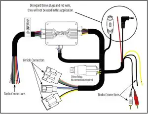
- Disregard the Red wire, it will not be used in this application.
- Tape off and disregard the 3.5mm jack, it will not be used in this application.
DIN jack:Disregard the DIN jack, it will not be used in this application.
Note: The relay attached to the AXGMMT-01 harness is only for audible turn signal clicks. No extra steps are required to retain this feature, so leave the relay as-is.
From the backup camera harness:
To the after market radio:
- Connect the Yellow RCA jack to the backup camera input.
To the vehicle:
- Connect the backup camera harness, to the male Gray connector removed from theHuman Machine Interface module (HMI). (Figure A)
For the Chevy Colorado and GMC Canyon:
• The HMI module is located in the radio cavity, down low.
For all other models:
- The HMI module is located behind the glove box. There are (2) modules behind the glove box. The HMI module is behind the metal dashboard support. (Figure B)
- Drop the glove box down by first removing the retaining cable on the right side. Then squeeze the glove box sides and gently pull down.
- Remove (6) T-15 Torx screws securing the plastic panel now exposed.
From the10-pinor 12-pinjumperharness to the vehicle:If the vehicle does not have a CD or DVD-Drive, disregard these steps.
For models without rear seat entertainment:
- Connect the female Black 10-pin jumper harness, to the male Black 10-pin harness removed from the CD-Drive.
For models with rear seat entertainment:
- Connect the female Black 12-pin jumper harness, to the male Black 12-pin harness removed from the DVD-Drive.Note: Even though this step must be done for models with rear seat entertainment, the rear seat entertainment system will not be retained by this interface.
AXSWC wiring:
If installing an AXSWC (sold separately), refer to the following instructions for wiring.
- Connect the Black wire to chassis ground.
- Connect the Red wire to accessory power.
- Connect the Pink wire, to the Green/Black wire in the 8-pin black connector located in the steering column. (Figure A)
- For the radios listed below: Connect the 3.5mm adapter priovided with the AXSWC, to the male 3.5mm jack from the AXSWC. Any remaining wires tape off and disregard.
- Eclipse: Connect the steering wheel control wire, normally Brown, to the Brown/White wire of the connector. Then connect the remaining steering wheel control wire, normally Brown/White, to the Brown wire of the connector.
- Metra OE: Connect the steering wheel control Key 1 wire(Gray) to the Brown wire.
- Kenwood or select JVC with a steering wheel control wire: Connect the Blue/Yellow wire to the Brown wire.
- XITE: Connect the steering wheel control SWC-2 wire from the radio to the Brown wire.
- Parrot Asteroid Smart or Tablet: Connect the 3.5mm jack to the AXSWCH-PAR (sold separately), then connect the 4-pin connector from the AXSWCH-PAR into the radio.Note: The radio must be updated to rev. 2.1.4 or higher software.
- Universal “2or3 wire” radio: a) Connect the steering wheel control wire, referred to as Key-A or SWC-1, to the Brown wire of the connector. Then connect the remaining steering wheel control wire, referred to as Key-B or SWC-2, to the Brown/White wire of the connector. If the radio comes with a third wire for ground, disregard this wire.Note: After the interface has been programmed to the vehicle, refer to the manual provided with the radio for assigning the SWC buttons. Contact the radio manufacturer for more information.
- For all other radios: Connect the 3.5mm jack into the jack on the aftermarket radio designated for an external steering wheel control interface. Refer to the manual provided with the aftermarket radio if in doubt as to where the 3.5mm jack goes to.
INSTALLATION
With the key in the off position:
- Connect the 16-pinharness with stripped leads, and the AXGMMT-01harness into the interface.
- Connect the AXGMMT-01harness to the wiring harness in the vehicle.
- If an AXSWC (sold separately) will be used, do not connect it until the AXGMMT-01 is programmed and fully functional.
PROGRAMMING
AXGMMT-01 programming:
Attention! If the interface loses power for any reason, the following steps will need to be performed again.
- Turn the key (or push-to-start button) to the ignition position and wait until the radio comes on.Note: If the radio doesn’t come on within 60 seconds, turn the key to the off position, disconnect the interface, check all connections, reconnect the interface, then try again.
- Turn the key to the off position, then to the accessory position. Test all functions of the installation for proper operation, before reassembling the dash.
AXSWC programming:
- With the key still cycled on, plug the AXSWC in. The LED in the AXSWC will flash rapidly.
- Tap the Volume Up button on the steering wheel at a heartbeat pace until the LED stop flashing rapidly.
- After approximately 2 seconds there will be a series of 7 Green flashes, some short, and some long. The long flashes represent the wires that are connected to the AXSWC.
- The LED will pause for another 2 seconds, then flash Red up to (18) times depending on which radio is connected to the AXSWC. Refer to the L.E.D. feedback section for information.
- This is the end of the auto detection stage. If the AXSWC detected the vehicle and the radio successfully, the L.E.D. will light up solid.
- Test the steering wheel controls for proper operation. Refer to AXSWC documents online for customizing the buttons, if so desired.
L.E.D. feedback
The (18) Red L.E.D. flashes represent which brand radio the AXSWCis connected to. Each flash represents a different radio Manufacturer. For example, if you are installing a JVC radio, the AXSWC will flash Red (5) times, and then stop. Following is a legend that dictates which radio Manufacturer corresponds to which flash.
L.E.D. feedback legend
|
Flash Count |
Radio |
|
1 |
Eclipse (type 1) † |
|
2 |
Kenwood ‡ |
|
3 |
Clarion (type 1) † |
| 4 |
Sony / Dual |
|
5 |
JVC |
| 6 |
Pioneer / Jensen |
|
7 |
Alpine* |
| 8 |
Visteon |
|
9 |
Valor |
| 10 |
Clarion (type 2) † |
|
11 |
Metra OE |
| 12 |
Eclipse (type 2) † |
|
13 |
LG |
| 14 |
Parrot ** |
|
15 |
XITE |
| 16 |
Philips |
|
17 |
TBD |
| 18 |
JBL |
- * If the AXSWC flashes Red (7) times, and you do not have an Alpine radio connected to it, that means the AXSWC doesn’t detect a radio connected it. Verify that the 3.5mm jack is connected to the correct steering wheel jack/wire in the radio.
- ** The AXSWCH-PAR is required (sold separately). Also, the Parrot radio must be updated to rev. 2.1.4 or higher through www.aparrot.com.
- † If you have a Clarion radio and the steering wheel controls do not work, change the radio type to the other Clarion radio type; same for Eclipse. Refer to the AXSWC document online for changing the radio type.
- ‡ If you have a Kenwood radio and the L.E.D. feedback comes back as showing as a JVC radio, change the radio type to a Kenwood. Refer to the AXSWC document online for changing the radio type.
AUDIO LEVEL ADJUSTMENT
- With the vehicle and radio turned on, turn the volume up 3/4 of the way.
- Locate the end of the AXGMMT-01, where the 16-pin harness with stripped leads connects to.
- With a small flat-blade screwdriver, adjust the potentiometer clockwise to raise the audio level; counterclockwise to lower the audio level.
- Once at a desired level, audio level adjustment is complete.
TECHNICAL SUPPORT
Having difficulties? We’re here to help.Contact our Tech Support line at:![]() Tel: 386-257-1187
Tel: 386-257-1187![]() Or via email at: [email protected]
Or via email at: [email protected]
Tech Support Hours (Eastern Standard Time)
- Monday – Friday: 9:00 AM – 7:00 PM
- Saturday: 10:00 AM – 7:00 PM
- Sunday: 10:00 AM – 4:00 PM
 KNOWLEDGE IS POWER Enhance your installation and fabrication skills by enrolling in the most recognized and respected mobile electronics school in our industry.Log onto www.installerinstitute.com or call 800-354-6782 for more information and take steps toward a better tomorrow.
Metra recommends MECP certified technicians
 report this ad
© COPYRIGHT 2021 METRA ELECTRONICS CORPORATION
References
[xyz-ips snippet=”download-snippet”]