![]() OPERATION MANUALRain Detector REGMEmodel 12 V AC/DC or 24 V AC/DC
OPERATION MANUALRain Detector REGMEmodel 12 V AC/DC or 24 V AC/DC
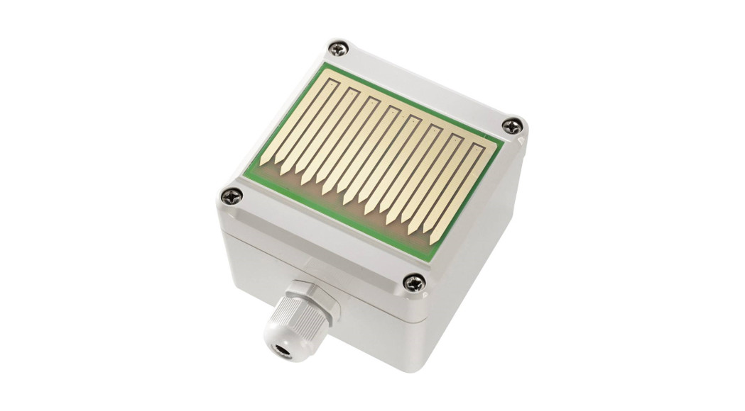
Description

Technical Data
| Technical Data | |
| Measurement method | Electrolytic AC measurements |
| Input current12 V Model24 V Model | 60 mA, Heater 80 – 300 mA (PTC)50 mA, Heater 40 – 180 mA (PTC) |
| CE-Conformance | 2014/30/EU |
| EMV-noise emission | EN 61000-6-3:2011 |
| EMV-noise withstanding | EN 61000-6-1:2007 |
| Cable gland | M16 x 1,5 |
| Operating voltage choosable: | 12 V AC/DC ± 10%24 V AC/DC ± 10% |
| Output | output (relay) 30 V / 4 A,NO / NC selectable |
| Housing | ABS, ingress protection IP54 |
| Dimensions (w x h x d) | 80 x 82 x 58 mm |
| Article | Art.-No. |
| Rain Detector 12 V | REGME-12V |
| Rain Detector 24 V | REGME-24V |
| Combined wall/mastmounting bracket | REGME-WAHA |
Features
- Safe operation, the electrolytic measurement principle
- Deposition can be detected as rain or snow
- Operating voltage 12 or 24 V DC/AC
- Large, heated sensor area for fast drying and operation in the winter season
- Potential free contact output (Relay) 30 V/4 A
- Sensitivity and switching mode adjustable
- Universal wall/mast mounting bracket as accessories
Applications
- Nurseries, Agriculture
- Control of Ventilation panels
- Automatic switch for Blinds and Rolling windows
- Building instrumentation
- Weather stations
Functional descriptionThe large sensor area reacts to rain or snow. The switch polarity and sensitivity are adjustable. The optionally switched heater prevents freezing or dew formation and accelerates drying. In the maximum sensitivity setting, the device is also suitable for recognizing fog. ApplicationThe rain guard is fitted with a relay contact for switching low voltages up to 30 V DC/AC which can be used to operate any switching device e.g. a marking control device. Sensitivity can be adjusted within a wide range. The device is provided with a heater for faster drying and snow recognition.Mounting Installation of the rain sensor unit should be carried out by only Authorised personnel. The applicable safety regulations should be followed! The Rain Sensor can be installed on a wall/mast mounting bracket. If such accessories are not used, care should be taken that the mounting angle is approximately 30 ° from horizontal. The points of the sensor area must be on the downside. Mounting of the Rain Sensor should be done at a place that is freely accessible for rain. Dripping water can adversely delay switching back or can lead to a permanent ON/OFF of the contacts.
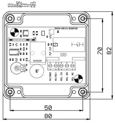
ConnectionAfter removing the sensor cover, the control cable is to be inserted in the cable gland M16.The supply voltage is to be connected to the terminals VCC and GND.Terminals NC, COM, NO are the potential free changeover contacts for switching.Precautions:
- The device is suitable only for low voltages and should not be operated on mains supply!
- The relay contact is only suitable for low-value signals and should not come in contact with the mains supply!
- The protection type is valid only with an intact, complete casing, cover screws, and cable gland properly tightened, and the cover gasket should always be available on the sensor cover!
- The suitability for certain applications is to be checked by the user
SettingsSignal generator output (optional)At the connection terminals (Pin BUZ and GND) a passive Piezo signal generator can be connected. The condition of signal (acousticsignal for dry or wet) can be selected with the plug links S1-S2 or S2-S3. In the default position S2-S3, the signal generator is inactive for rain.Switching modeThe switching mode of the relay (pickup or dropout with rain) can be selected with the plug links T1-T2 or T2-T3. In the factory settings, link T1-T2 is connected and the relay closes if the sensor surface gets wet.HeatingThe sensor surface is heated if the link of HZ1-HZ2 is connected. To ensure faster drying and for operation below freezing point, the heater should be switched on. For sensing fog, the heater can be switched off.Sensitivity settingThe sensitivity for detecting rain can be adjusted with the potentiometer. Rotating the potentiometer clockwise results in a higher sensitivity.For detecting rain mostly the middle position of the potentiometer is suitable. Please note that no function takes place in the end position!IndicatorsThere is a green LED on the device to indicate the operation status and a red LED to indicate the switch position (means relay contact closed).MaintenanceThe Rain Sensor unit is almost maintenance-free. The sensor surface must be occasionally cleaned with a moist cloth ( e.g. once annually, depending on the place of installation). In case of the persistent condition, even if it does not rain, it triggers due to strong
| Connection Layout | |
| REL NC | Opening switch contact |
| REL NO | Closing switch contact |
| REL CO | Common switch contact |
| AC/DC | Operating voltage AC or 24 V DC +10% |
| AC/GND | Operating voltage AC or 0 V |
| Plug Links Configuration | ||
| 1 | S3 | Switch mode signal generator (dry) |
| 2 | S2 | Common contact to S3 and S1 |
| 3 | S1 | Switch mode signal generator (wet) |
| 4 | GND | Signal generator ground |
| 5 | BUZ | Signal generator output |
| 6 | T3 | Switch mode relay (dry) |
| 7 | T2 | Common contact to T3 and T1 |
| 8 | T1 | Switch mode relay (wet) |
| 9 | HZ1 | Heating |
| 10 | HZ2 | Heating |
| factory setting: S3 – S2, T1 – T2, HZ1 – HZ2 |
Dimensions
 Accessorieswall/mast mounting bracket including mounting hardware attention Please avoid extreme mechanical and inappropriate exposure. The device/product is not suitable for potentially explosive areas and medical-technical applications.
Technical changes reserved0141 0316-212 20.04.2016B+B Thermo-Technik GmbH | Heinrich-Hertz-Straße 4 | D-78166 DonaueschingenFon +49 771 83160 | Fax +49 771 831650 | i[email protected] | bb-sensors.com
 report this ad
References
[xyz-ips snippet=”download-snippet”]