BAL Powered ‘C’ Type Stabilizing Jack Instruction Manual
PARTS DIAGRAM
| Item # | Part # | Description | Qty |
| 1 | P855132 | Link, Black – 25 ‘C’ Jack 12.5 | 4 |
| 2 | P855130 | Arm Assy, 25 in | 2 |
| 3 | 502113 | Hex Bolt, 3/8-16 x .75 | 2 |
| 4 | 501063 | Loc-Nut, 3/8-16 Hex | 4 |
| 5 | R853050 | Hex Bolt, 3/8-16 x 4.00″ | 2 |
| 6 | 23100 | Foot Pad, ‘C’ Jack single | 2 |
| 7 | 854171 | Screw, Self-Tapping 10-24 x 0.75 | 4 |
| Item # | Part # | Description | Qty |
| 8 | 855134 | Threaded Drive Rod, 25″ ‘C’ Jack | 2 |
| 9 | 20300030 | Coupler, ‘D’ to Square | 2 |
| 10 | 231000 | Motor, Elec Jack Gearbox Assy 12v | 2 |
| N/S | R857076 | Clip, Retainer – Drive Rod | 2 |
| N/S | R270399 | Screws, Mounting, 1/4″ | 8 |
| N/S | 20300027 | Switch, 12 volt black | 2 |
| N/S | 20300031 | Breaker, 12 volt resetting, 15 Amp | 2 |
INSTALLATION AND OPERATING INSTRUCTIONS
THIS POWERED STABILIZING JACK IS DESIGNED FOR:FINE LEVELING AND STABILIZING TRAVEL TRAILERS AND 5TH WHEEL TRAILERS
WARNING!
- DO NOT USE A CORDLESS DRILL TO OVERIDE THE STABILIZING JACKS. DAMAGE TO GEARBOX MAY OCCUR.
- DO NOT ATTEMPT TO USE THIS STABILIZING JACK TO LIFT EXCESSIVE WEIGHT OR TIRES OFF THE GROUND – VEHICLE FRAME AND DOOR JAMB DAMAGE MAY OCCUR.
- DO NOT ATTEMPT TO USE THIS STABILIZING JACK FOR PURPOSES OTHER THAN ITS INTENDED DESIGN.
CAUTION: Some RV’s may be designed and manufactured with sub frames that are not capable of handling additional force over and above the intended strength to support the cabin weight. Contact your RV manufacturer for sub-frame strength information prior to using this Powered ‘C’ Jack. NORCO CANNOT BE HELD RESPONSIBLE FOR ANY DAMAGES DUE TO IMPROPER USE OF THIS PRODUCT. NORCO CANNOT BE HELD ACCOUNTABLE FOR THE STRUCTURAL INTEGRITY OF ANY RV FRAME.
TOOLS REQUIRED
Cordless power drill 3/16” diameter drill bit
3/8” wrench or socket assembly Wire strippers/crimpers
Dremel style cutting tool
DETERMINING THE CORRECT MOUNTING LOCATION
NOTE: Check ground clearance prior to installation.
TRAVEL TRAILER AND 5TH WHEEL TRAILER MOUNTING PLACEMENT
STEP 1: PARK ON LEVEL GROUNDFRONT: Draw a string from the front corner of the trailer frame to the bottom of the front tire (A).REAR: Draw a string from the bottom of the back tire to the back corner of the trailer frame (B).NOTE: ANY OBJECT PROTRUDING BELOW THESE LINES CAN BE DAMAGED, DRAGGED OFF OR DESTROYED INUNEVEN TERRAIN, ENTERING OR EXITING DRIVEWAYS, DRIVING OFF READ, ETC.
BEFORE PROCEEDING TO INSTALLATION – PERFORM THIS IMPORTANT TEST
To insure clearance for the jack in the closed position, clamp the jack to the vehicle frame using two “C” clamps or Vise Grips™. Close the jack with the crank handle and check to insure that the location chosen will allow the jack to close without coming into contact with or obstruct any under chassis components (ie: plumbing, exhaust, etc.)
ASSEMBLY OF JACK COMPONENTS
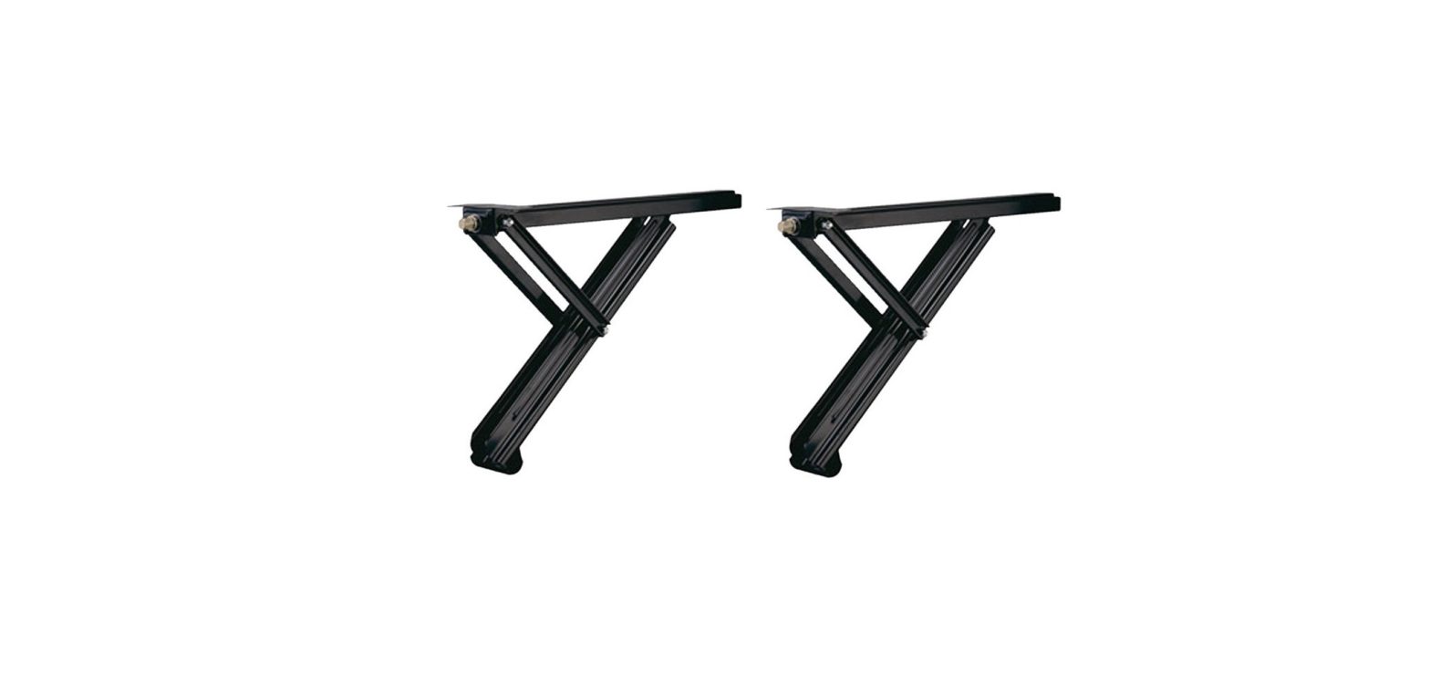
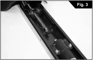
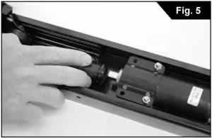
The Powered ‘C’ Type Stabilizing Jacks consist of two Jack Assemblies and one Motor Channel (Fig 1). Remove the contents and position the Jack Assemblies to accept the Motor Channel (Fig 2). The Motor Channel will slide over each Jack Assembly. You will see a flattened area on each end of the Threaded Rod (Fig 3). Slide the ‘D’ Motor Coupler over the Threaded Rod making sure to use the Coupler end that looks like a letter ‘D’ (Fig 4). Slide the Motor Channel towards the Coupler and onto the square end of the 12v Motor (Fig 5). Once firmly in place, use a powered screwdriver drill to install the Self Tapping Screws to secure the Motor Channel to the Jack Assembly. There are predrilled holes in the Motor Channel to use as a guide (Fig 6). Be careful to not overtighten and strip the threads. If you do, you will need to replace the Self Tapping Screws with bolts and nuts (not included). Repeat procedure on opposite side.
INSTALLATION OF JACK ASSEMBLY
BAL Powered ‘C’ Type Stabilizing Jacks are designed to mount to the bottom of the trailer frame that allows for a minimum of 8” surface of unobstructed mounting location on each side of the trailer. The Jack assembly will fit on trailer frame widths of 66.5” to 70.5”. In some cases, screws or bolts used to attach the underbelly skirt might need to relocated. Factory installed items such as LP or electrical lines, plumbing, slide out structure, etc. need to be considered before mounting Jack assembly. Depending on your trailer frame, you can use the included mounting screws to mount the Jack assembly to the frame. In certain installations, you will need to bolt thru the frame and secure with bolts, washers, and nuts (not included). This would be required when the frame locations is thicker requiring longer mounting bolts, if the frame material is thin gauge, or when you are replacing an existing jack system and the bolt holes are too large for the mounting screws.
After determining the mounting location, use the hole locations on the Jack assembly frame brackets as a template for drilling screw holes (Fig 7). Once they are marked, use drill bits to make a 3/16” hole. Be sure to inspect frame location to avoid damaging any factory installed items such as LP or electrical lines, plumbing, slide out structure, etc. Once the holes are predrilled, use a 3/8” wrench to install the mounting screws thru the brackets into the frame.
12V ELECTRICAL WIRING
STEP 1A: For new wiring installations, it is recommended to mount the switches in a location that you can view the operation of each jack. If you choose to mount both switches in the same location, please consider the line of sight for each jack. The holes for mounting the switches can be cut using a Dremmel style tool depending on the surface material. If you are mounting into fiberglass, use a drill to create a starter hole at each corner (drill in reverse to start the hole which helps reduce a chance of spider cracks in the fiberglass). You will need to run a minimum of 10 AWG wire (not included) directly from the battery to each switch. If you choose to mount the switches next to each other, you can use the same wire from the battery for both switches but you will not be able to operate both jacks at the same time. Once you have run the wires from the battery to the switch, use the diagram to wire up the switches (Fig 8). From the switch, wire each switch separately to the included 12v breakers. From each breaker, wire to the center of the Jack assembly. Be sure to firmly secure the wires with proper electrical connectors and electrical tape for protection.
STEP 2A: For wiring when replacing an existing, non-BAL jack system, the established wire can be used only if it is a minimum of 10 AWG wire. Anything smaller will need to be removed and replaced. If the existing wire is sufficient, check for preinstalled 12v breakers similar to the ones supplied in this kit. Identify the amperage the breakers. If they are less than 15A, they will need to be removed and discarded. If they are 15A and above, they can be kept and used in conjunction with the breakers included in this kit. If there is only one set wires from the breaker to the existing switch, it can be used for both BAL switches but do not operate both jacks at the same time.
Existing system with two switches: Use the two new Switches in kit & duplicate the wiring procedure in Step 1A.
Existing system with only one switch: If you plan on installing both switches at the original, single switch location, the existing hole will need to be enlarged. Refer to suggestions in Step 1A for guidance on cutting the hole. In either switch mounting situation, a second wire (not included) will be added from the second switch to the included 12v breaker to the Jack assembly (Fig 8).
Switch Wiring Tips: If the Jack operates in the opposite direction of the switch position you can reverse the wires from the battery to the switch changing the polarity and operation direction of the jack.
OPERATION
STEP 1: Park RV on as level of ground as possible. Chock wheels to prevent rolling.
STEP 2: Level trailer fore and aft using tongue jack or landing gear.
STEP 3: Using a bubble level, check for low side of trailer and operate the lowest corner of the trailer first bring the trailer to a fine level position.
STEP 4: Move to the next lowest corner operating the jack bring the trailer to a fine level position.
STEP 5: Continue to final corner locations (if needed) to operate jacks into position to insure maximum stability.
STORAGE: Before moving trailer, operate each switch individually to store Jacks against frame.
MAINTENANCE: Apply a lubricant of your choice to the treaded rod while in the down (open) position. The lighter the grade of lubricant will require more frequent applications. The heavier the lubricant will last longer however could attract more dust and debris. No lubrication to the motor is required.
WARNING: DO NOT ATTEMPT TO USE THIS JACK TO LIFTEXCESSIVE WEIGHT OR TIRES OFF OF THE GROUND. VEHICLE FRAME AND DOOR JAMB DAMAGE MAY OCCUR. USE ONLY STOCK HANDLE SUPPLIED. DO NOT USE A CHEATER BAR ON HANDLE. DO NOT USE THIS JACK AS A TIRE CHANGING JACK.
TECHNICAL SUPPORT
PHONE: 877-557-7788EMAIL: [email protected]
www.balrvproducts.com • BAL R.V. PRODUCTS • 310-639-4000
 report this ad
www.balrvproducts.com • BAL R.V. PRODUCTS • 310-639-4000
References
[xyz-ips snippet=”download-snippet”]