
LEVELING SYSTEM MADE IN USA NORCO INDUSTRIES, INC.
5th Wheel Electric Leveling System
 |
|
User Manual
20300513
![]()
- NEVER USE THE LEVELING SYSTEM AS A LIFT FOR CHANGING TIRES OR WORKING UNDER THE UNIT.
- KEEP PEOPLE AND PETS CLEAR OF THE UNIT BEFORE TURNING THE LEVELING SYSTEM ON AND WHILE OPERATING THE SYSTEM.
- ALWAYS CHECK THE TIRES BEFORE DISCONNECTING THE UNIT FROM THE TOW VEHICLE AND/OR OPERATING THE LEVELING SYSTEM.
- PARK UNIT ON REASONABLY SOLID SURFACE SO THAT JACKS WILL NOT SINK INTO THE GROUND. ON EXTREMELY SOFT SURFACES USE LOAD DISTRIBUTION PADS UNDER EACH JACK.
- PARK UNIT ON REASONABLY LEVEL SURFACE MAKING SURE THAT THE JACK CONTACT LOCATIONS ARE CLEAR OF OBSTRUCTIONS AND DEPRESSIONS BEFORE OPERATING THE SYSTEM.
- ALWAYS MAKE SURE THAT THE TOW VEHICLE IS DISCONNECTED AND MOVED COMPLETELY CLEAR OF THE FRONT OF THE UNIT BEFORE THE LEVELING PROCESS IS STARTED.
- NEVER LIFT THE WHEELS OF THE UNIT COMPLETELY OFF THE GROUND TO LEVEL THE UNIT.
- ALWAYS CHECK TO ENSURE THAT THE UNIT IS PROPERLY CONNECTED TO THE TOW VEHICLE BEFORE EXECUTING THE “LANDING GEAR RETRACT” FUNCTION.
- VISUALLY CHECK ALL JACKS TO ENSURE THAT THEY ARE FULLY RETRACTED BEFORE TOWING THE UNIT.
- FAILURE TO HEED ANY OF THESE WARNINGS MAY RESULT IN DAMAGE TO THE UNIT, TOW VEHICLE, AND/OR CAUSE SERIOUS INJURY OR DEATH.
STANDARD PROCEDURES & AUTOMATED FUNCTIONS
NOTE: At any time during an Auto function you may press STOP to abort the Auto function.When buttons are outlined in white the function may be selected.When buttons are outlined in yellow the function is active.
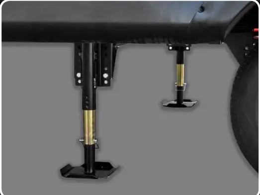
UNIT DETACHMENT AND AUTO-LEVELLower the landing gear adjustable feet, and position them so they are approximately the same distance from the ground. Chock the wheels.

Press ON/OFF to activate the display. Press LANDING GEAR MODE. Press and hold EXTEND until the necessary detachment height is reached. Disconnect, and pull the tow vehicle completely clear of the unit. Lower the rear leveling jack adjustable feet and position them so that they are close to the same distance from the ground. Press AUTO MODE.
Press AUTO LEVEL. WARNING: Vehicle, people, pets and obstructions must be completely clear of the unit before executing the “AUTO LEVEL” function. Press OK to begin “AUTO LEVEL” or STOP to make another selection.
The system will go through a series of moving the jacks and checking the unit for level. The display will read “AUTO LEVEL IN PROGRESS”. When the system has successfully leveled the unit, the display will read “AUTO LEVEL SUCCESSFUL” and a beep will sound.
Press ON/OFF to deactivate the display.
NOTE: If the system fails to Successfully Auto Level, check the unevenness of the area under the unit. All lifting jacks must be able to make full contact for the system to function properly.
UNIT ATTACHMENT
Press ON/OFF to activate the display, and press AUTO MODE. Press AUTO RECONNECT. WARNING: Vehicle, people, pets, and obstructions must be completely clear of unit before executing the “AUTO RECONNECT” function. Press OK to begin “AUTO RECONNECT” or STOP to make another selection.
The system will retract all stabilizer jacks (if equipped) and the rear leveling jacks, then extend or retract the landing gear until the proper connection height is achieved. The display will read “AUTO RECONNECT IN PROGRESS “. When the system has completed the “AUTO RECONNECT” function the display will read “AUTO RECONNECT SUCCESSFUL” and a beep will sound. If the unit does not reach the proper height the first time, simply repeat the “AUTO RECONNECT” process. (Not reaching the reconnect height the first time may be due to a large difference between the level and reconnect heights.)
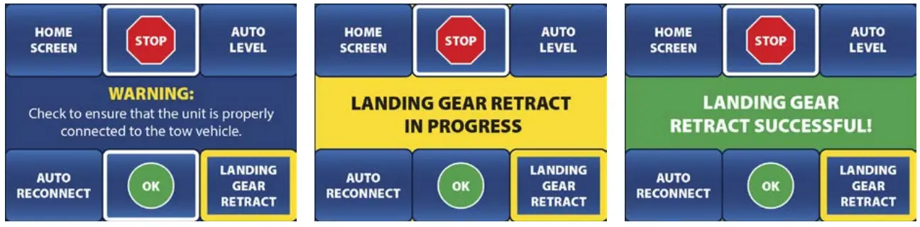
Connect the unit to the tow vehicle. Press AUTO MODE. Press LANDING GEAR RETRACT.WARNING: Always check to ensure that the unit is properly connected to the tow vehicle before retracting the landing gear.
Press OK to begin “LANDING GEAR RETRACT” or STOP to make another selection. The display will read “LANDING GEAR RETRACT IN PROGRESS”. When the jack has been fully retracted the display will read “LANDING GEAR RETRACT SUCCESSFULly” and a beep will sound. If the “LANDING GEAR RETRACT” does not fully retract the jacks, simply repeat the “LANDING GEAR RETRACT” process, or use “LANDING GEAR MODE” to finish retracting the landing gear.
Raise all adjustable feet to the hole that provides the most ground clearance before towing the unit.Press ON/OFF to deactivate the display.WARNING: Visually check all jacks to ensure that they are fully retracted before towing the unit.
MANUAL MODE FUNCTIONS
NOTE: When buttons are outlined in white the function may be selected.When buttons are outlined in yellow the function is active.
MANUAL STABILIZER JACK MODE
Press ON/OFF to activate the display. Press MANUAL MODE. Press and hold EXTEND/RETRACT to operate the stabilizer jacks (if equipped). Press MANUAL MODE or HOME SCREEN to continue.
WARNING: Always make sure that the stabilizer jacks are fully retracted before operating the tongue jack or rear leveling jacks.
MANUAL JACK MODE
Press MANUAL MODE. Lower the rear leveling jack adjustable feet and position them so that they are close to the same distance from the ground. Use the bubble level on the display to guide you. When the bubble is in the center of the circle the unit is level. Always run the rear leveling jacks all the way to the the ground before leveling side to side.
Press and hold FRONT, REAR, LEFT, or RIGHT, and the jacks will move as follows:
- FRONT: Both landing gear jacks are on the front of the unit.
- REAR: Both leveling jacks on the rear of the unit (closest to the axles).
NOTE: Run the rear leveling jacks all the way to the ground before lifting side to side.
- LEFT: Both front and rear jacks on the left side (roadside).
- RIGHT: Both front and rear jacks on the right side (curbside).
To retract the jacks. Press RETRACT and then press and hold FRONT, REAR, LEFT, or RIGHT.The jacks will move in the same grouping as listed above.Press ON/OFF to deactivate the display.
CARE & MAINTENANCE
ROUTINE SYSTEM CHECKThe leveling system should be inspected a minimum of twice per year. (Once before starting the camping season and once before storing the unit). Inspect:
- Jacks for dirt and debris. (Clean and lubricate as needed)
- A high-pressure washer is not to be used to clean any of the leveling system components.
- Grease all jacks as shown:
- Landing Gear Jacks – Apply one or two pumps of grease to each grease zerk.

- Rear Leveling Jacks – With the jack extended halfway remove the plastic plug and apply a small amount of grease on the screw. Reinstall the plastic plug.
- Stabilizer Jacks (if equipped) – With the jacks extended so that they are about an inch from the ground apply some grease on the screw between the motor coupler and the trunnion nut.
- All jack mounting bolts and nuts for tightness. (Tighten as needed)
- Landing Gear – 18-20 ft. lbs.
- Rear Leveling Jacks – 80 ft. lbs.
- Stabilizer Jacks – 30 ft. lbs.
MANUAL JACK OVERRIDE
PROCEDURELocate the jack motor that is to be overridden.
Rear Jacks – At the bottom of the jackleg motor in the center there is a round rubber plug. Remove the rubber plug to expose the 5/16” override hex. Using a drill with a 5/16” drive socket rotate the motor to operate the lifting jacks.
Landing Gear – Using the manual crank handle, alternately crank each landing gear jack a few turns at a time to raise or lower the landing gear.

Stabilizer Jacks (if equipped) – To override the stabilizer jacks. Locate the ¾” nut on the out-facing end of the stabilizer jack. Use a 3/4 “socket or wrench to raise or lower the jacks.
DIAGNOSTICS
ERROR DISPLAY
AUTO LEVEL FAILED
- Problem: Rear raised too high during the auto-level process. (Without being able to lift side to side) This may be a sign of unstable ground.
- Solution: Move the unit into an area with stable soil or place load distribution pads under each jack. Minimize movement within the unit.
LOW VOLTAGE
- Problem: The leveling system must maintain 10.2 Volts at the control to operate for both functionality and system protection.
- Solution: Plug unit charging system in or replace the battery.
HIGH VOLTAGE
- Problem: The leveling system must be less than 16 Volts at the control to operate for both functionality and system protection.
- Solution: Verify charging system is working properly.
EXCESS ANGLE DETECTED
- Problem: The angle of the unit is too great to perform the operation.
- Solution: Move the unit into an area with lesser grade or unevenness.
MANUAL ADJUST ANGLE LIMIT
- Problem: Manual adjust angle limit.
- Solution: Use extends and retracts options to keep the unit reasonable level during manual operations. Try using Auto level or move the unit into an area with a lesser grade.
OUT OF STROKE
- Problem: The jackleg is fully extended.
- Solution: Move the unit into an area with the lesser grade, unevenness, or place load distribution pads underneath the jacks.
FEATURE DISABLED
- Problem: Zero point not set.
- Solution: Contact an Authorized Dealer to have the system Zero point set.
- Problem: Auto Reconnect position not set.
- Solution: Use Tongue Jack Mode to obtain disconnect position then Auto level before using Auto Reconnect.
JACK TIMEOUT
- Problem: The control is not seeing movement from the jacks.
- Solution: Check that the landing area is firm and within reach of the jack travel. Check all wire harnesses to make sure they are not damaged and that they are plugged in properly.
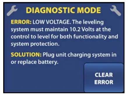
NOTE: After the problem has been resolved press CLEAR ERROR proceed.
report this ad© Copyright 2017 BAL, Inc.All rights reserved.BAL is a registered brand of Norco Industries, Inc.
Printed in the U.S.A.November 2017
[xyz-ips snippet=”download-snippet”]