Triple Mode InfraredTemperature-Testing Multimeter
CAT II500V
Security Information
![]() WarmingPeople who use this meter should pay special attention to it, because improper use might cause electric shock or damage to the meter. Please follow the actual safety rules and safety measures as specified in the manual.To fully use the function of this meter and ensure its safe operation, please read and follow its usage methods in the specification carefully.This meter matched the technical requirement of digital multimeter GB/T 13978-92 and the safety requirement of electronic measuring meter GB4793.1-1995 (IEC-61010-1. It belongs to secondary pollution and its over-voltage standard is CAT Ⅱ 500V.Please follow the safe operation guide and ensure the safe use of this meter.Proper use and maintenance for meters will give you satisfactory service.
WarmingPeople who use this meter should pay special attention to it, because improper use might cause electric shock or damage to the meter. Please follow the actual safety rules and safety measures as specified in the manual.To fully use the function of this meter and ensure its safe operation, please read and follow its usage methods in the specification carefully.This meter matched the technical requirement of digital multimeter GB/T 13978-92 and the safety requirement of electronic measuring meter GB4793.1-1995 (IEC-61010-1. It belongs to secondary pollution and its over-voltage standard is CAT Ⅱ 500V.Please follow the safe operation guide and ensure the safe use of this meter.Proper use and maintenance for meters will give you satisfactory service.
Preparation
- Users must follow the standard safety rules when using it:– Need some universal protection to avoid electric shock.– To avoid misuse of the meter.
- Check if there is any damage on this meter or not in the process of transportation when received it.
- Check if there is any damage on this meter or not when preserved, loaded, and delivered it in poor condition.
- The test lead must be in a good condition. Check whether there is any damage to its insulation or not and if the meter’s metal wire is exposed or not before using it.
- Using the test lead provided by the meter can guarantee the use of meter safety. If needed, you must use the same or similar pen to replace it.
Usage
- The correct function and measuring range must be guaranteed when using it.
- Don’t overtake the indicating value of protection extent of every measuring range when testing.
- Don’t touch the top of the test lead (the metal part) when linked the meter with the measuring circuit.
- When testing, if the voltage tested is over 60V DC or 30V AC (RMS), please keep your fingers behind the test lead protector.
- When the measuring terminal voltage is over 500V DC or 500V AC, please stop testing voltage.
- Before turning the switch to change the testing function, the test lead should be removed from the measuring circuit.
- Do not measure resistance and lines when the line is energized.
- When use resistance and circuit breaker, the user should avoid linking the meter with a voltage source.
- Don’t use the meter under the explosive gas, steam, or dust environment.
- If there is any abnormality or malfunction in the meter, the user should stop using it.
- Multimeter should not be used unless the meter bottom shell and the battery cover are completely clasped in place.
- Don’t preserve or use meters in the condition of direct sunlight, high temperature, high humidity.
Marks![]() It can be used on hazardous live conductors.
It can be used on hazardous live conductors.![]() Warning sign
Warning sign![]() Double insulation protection.(II Level)CAT II In accordance with the IEC-61010-1 standard over-voltage (installation) level II, pollution level 2, CAT II means the level of pulse withstand voltage protection provided.Matched EC(EU) standard.
Double insulation protection.(II Level)CAT II In accordance with the IEC-61010-1 standard over-voltage (installation) level II, pollution level 2, CAT II means the level of pulse withstand voltage protection provided.Matched EC(EU) standard.
Product Description
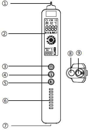
- Part Name
No. Description 1 V~Alert sensor area 2 Display 3 Power switch 4 Flashlight switch 5 Infrared temperature testingswitch 6 Voltage signal indicator 7 Input terminal 8 Infrared temperature-testing sensor area 9 Flashlight 
- Key Description Power switch Flashlight switch button: turn on the flashlight. Infrared temperature-testing switch: Press and hold to keep infrared temperature measurement test; While measuring the infrared temperature, press and hold the switch button for 2 seconds to switch the unit of °C/℉
- LCD full display symbol

| Symbol | Elaborate on |
| Voltage AC | |
| Voltage DC | |
| Continuity | |
| The battery is low and should be changed | |
| AUTO | Automatic range measurement mode |
| Auto power-off function indication | |
| VALT | Non-contact AC voltage detection/NCV |
| Non-contact AC voltage detection/NCV | |
| Infrared Temperature-Testing | |
| MAY | Maximum temperature |
| V | Voltage unit: volt |
| Hz | Hertz, Kilohertz, Megahertz |
| Ω, KΩ, MΩ | Resistance unit: Ohm, kilohm, megaohm |
| Celsius, Fahrenheit (temperature) |
Specification
Automatic measuring range.Full measuring range overload protection.Maximum voltage allowed at the measuring end.:500V DC or 500AC(RMS).Work height: maximum 2000mDisplay: LCD.Maximum display value: 2000 digits.Polarity indication: Self-indicating, ‘-’ means Negative polarity.Over-range display:‘0L’ or ‘-0L’.Sampling time: The meter figures show about 0.4 secondsUnit display: Function and battery unit display.Automatic Power-off time: 5 minutesOperational power:1.5Vx2 AAA battery.Battery low voltage indication: LCD display ![]() symbol.Temperature coefficient:Less than 0.1 x Accuracy / ℃Operational temperature and humidity : 0~40 ℃/32~104℉、45%-80%RHStorage temperature and humidity:-10~60 ℃/-4~140℉、45%-80%RHBoundary dimension:181×28×31mmWeight: ~87g
symbol.Temperature coefficient:Less than 0.1 x Accuracy / ℃Operational temperature and humidity : 0~40 ℃/32~104℉、45%-80%RHStorage temperature and humidity:-10~60 ℃/-4~140℉、45%-80%RHBoundary dimension:181×28×31mmWeight: ~87g
Technical index
AccuracyAccuracy applies within one year of calibration.Reference conditions: environmental temperature 18 ℃ to 28 ℃, the relative humidity is not greater than 80.
Voltage DC
| Range | Resolution | Accuracy |
| 500V | 0.1V | ±(0.8%+3counts) |
- Sensitivity: minimum 0.5V DC voltageInput impedance: 1MΩMaximum input voltage: 500V DC &AC (RMS)
- Voltage AC
Range Resolution Accuracy 500V 0.1V ±(1.2%+5counts) Sensitivity: minimum 1V DC voltageInput impedance: 1MΩMaximum input voltage: 500V DC&AC (RMS)Frequency range: 50Hz~60Hz, true RMS response.
- Resistance
Range Resolution Accuracy 6000Ω 1Ω ±(1.2% +3counts) Overload protection:500V DC or AC(RMS)
- Frequency
Range Resolution Accuracy 1000Hz 0.1Hz ±(1.0%+5counts) Frequency range: 40Hz~1000Hz.
- Measure Continuity
Function Accuracy If the resistance is <30Ω, the continuity beepersounds. Overload protection:500V DC or AC(RMS)
- V~Alert
Range Explanation Low-range Green voltage signal indicator.The screen displays 1/3 analog bar, the buzzer sounds a slow alarm.
Mid-range Yellow voltage signal indicator.The screen displays2/3 analog bar, the buzzer sounds a quick alarm. High-range Red voltage signal indicator.The screen displays fullanalog bar,the buzzer sounds a very loud alarm. Voltage range:90V~1000V AC
- High sensitivity mode
Range Resolution Accuracy 0℃~380℃32℉~716℉ 0.1℃0.1℉ ±(2.5%counts+2℃)±(2.5%counts+35.6℉) -20℃~0℃-4℉~32℉ 0.1℃0.1℉ ±(2.5%counts+3℃)±(2.5%counts+37.4℉) Temperature range: -20℃~380℃(-4~716℉)Emissivity: 0.95Spectral range:8-14umResponse time:~1sD:S= 6:1
Operation Instructions
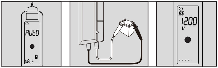
Voltage DC or AC/Frequency/Resistance/Measure Continuity
- Insert the red test lead into the “INPUT” terminal, black test lead into the “COM” terminal.
- Connect the test leads in parallel to the circuit, power supply, tested resistor. The meter automatically Identify whether it is AC voltage, DC voltage or resistance, and shows the frequency on the screen.
- When resistance is less than 30Ω, the buzzer sounds.
- When measuring DC voltage, it can also show the voltage polarity of the red test lead.
- Read the measurement results from the display.Voltage DCVoltage AC FrequencyResistanceMeasure Continuity
 Voltage AC Frequency
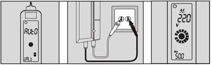 Resistance
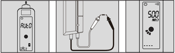 Measure Continuity
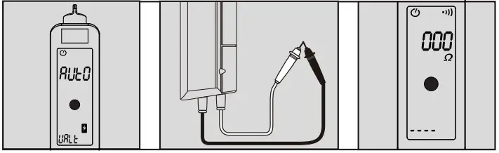
Warning:
- Do not input voltages higher than 500V, showing higher voltages are possible, but it may destroy the meter.
- When measuring high voltage, be careful to avoid electric shock.
- Disconnect the test leads from the circuit when completed measurement.
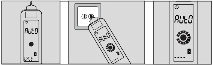
Non-contact AC voltage detection
- Press the power button.
- Put the sensor head into the power outlet or near the electrified lead wire, and when the tester detects the AC voltage signal, the voltage signal flicks the signal, the bar value of the meter screen lights up, and the test is based on the intensity of the signal detected, lighting the corresponding signal strength indicator lights (high, medium, low), and the buzzer emits different frequencies of the alarm sound.
- Push the inductive head of the tester close to the wire, plug the probe into the jack. The tester detects that one of the strong induced signals is a live wire, and the weak or non-sensing signal of the induction signal is the neutral wire.Non-contact AC voltage detection
Warning:
- Non-contact AC voltage and live wire detection operations may be influenced by the socket design, insulation thickness, and class.. Even without indication, the voltage may still exist. Do not use a non-contact voltage detector to determine whether the voltage existence.
- When input voltage, the non-contact voltage sensing indicator may light on because of the existence of induced voltage
- Outside environment (such as flash, motor, etc.) may influence the non-contact voltage detection.
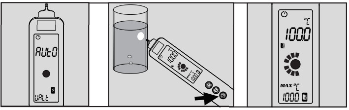
Infrared Temperature-Testing
- Press the power button.
- Press and hold to keep infrared temperature-testing.
- The tester infrared temperature sensing area close to the object 5-10cm (recommended distance).
- Read the measurement result from the display screen, and view the dynamic change of the value through the analog bar.
- You can turn on the flashlight to assist in observing the test range area, and the lighting range area is basically the same as the infrared temperature sensing range area.
Maintenance
![]() WarningTo avoid shock hazards, users should remove the pen from the testing circuit before opening the battery cover of the meter.
WarningTo avoid shock hazards, users should remove the pen from the testing circuit before opening the battery cover of the meter.
General Maintenance
- Do not operate the product around hot, wet, flammable, explosive, or magnetic environments.
- Clean the product with a damp cloth and mild detergent; do not use abrasives or solvents.
- Remove the input signals before you clean the product.
- Remove the batteries if you will not use the product for a long time to prevent possible battery leaks.
Replace Battery
- If “ ” symbol appears, it means the battery shall be replaced.
- Remove the test leads from the terminals.
- Loosen the battery door fastener and remove the door from the case bottom.
- Remove the batteries.
- Replace the batteries with two new AAA batteries.
- Reattach the battery door to the case bottom and tighten the fastener.
Note:Do not violate the battery polarity.
[xyz-ips snippet=”download-snippet”]