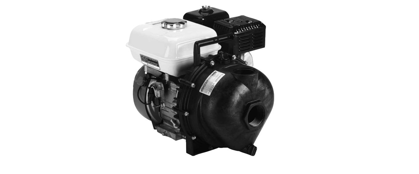
BANJO Self-priming Poly Centrifugal Pumps Instruction Manual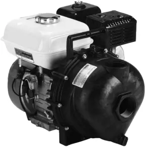
OVERVIEW
Read these instructions and the instructions covering operation of the pump drive unit.
The gas engine (if so equipped) is shipped with no oil. Consult your owners manual for specific oil recommendations, maintenance procedures, schedules, and troubleshooting. The maximum angle of operation for gas engine drive units is 25° in all directions. For engine warranty service contact your local engine dealer.
Make certain that all hose and pipe connections are air tight. An air leak in the suction line may prevent priming and will reduce the performance of the pump.
Always place the pump as close to the liquid to be pumped as possible. Keep the suction line short and with few bends.
Keep the pump and engine on a level foundation. A poor foundation and a heavy suction hose (made heavier when “primed” full of liquid) could result in a pump “down the hole”. It is not necessary to drain the pump body after use, unless there is a danger of freezing.
There are no points on the pump that need lubrication. The pump seal is cooled and lubricated by the fluid being pumped. When pumping dirty water or liquids containing solids, always use a pump strainer on the end of the suction line. Note: Engine warranty service available at authorized Briggs & Stratton® and Honda® dealers.
WARNINGS
OPERATION WARNING
Do not operate the gas engine (if so equipped) until you have put oil in the engine. Do not run the pump dry. Serious damage to the mechanical seal or complete failure of the mechanical seal can result from running the pump dry. Always fill the pump with water or the fluid being pumped before starting the drive unit.
STORAGE WARNING
There are important instructions regarding the preparation of the engine for long periods without use, (reference the engine instruction manual). Before long periods of storage, the pump should be flushed with clean water and drained. Leave all plugs (fill and drain) out of the pump. Always store the pump unit in a heated and dry building.
WARNING! DO NOT USE WITH FLAMMABLE LIQUIDS.Do not use flammable liquids. This pump is not designed or produced to pump flammable liquids of any kind. Failure to follow this warning can result in explosion, serious bodily injury or death.
PERFORMANCE
1½″, 2″ & 3″ POLY PUMPS
1½″ Port Size
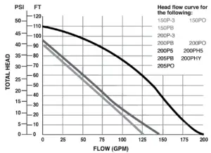
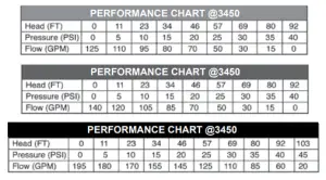 Note: Curve based on water and pump spinning at 3450 RPM
- Suction: 1½″ NPT
- Discharge: 1½″ NPT
2″ Port Size
- Suction: 2″ NPT
- Discharge: 2″ NPT
3″ Port Size
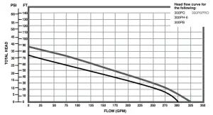

- Suction: 3″ NPT
- Discharge: 3″ NPT
DISASSEMBLY INSTRUCTIONS:
Remove the 10 body screws (12720), lock washers (V07018) and nuts (V07019) from the pump assembly. Remove the body from the pump assembly.
Remove the check valve (12705) from the volute (12702A/13702).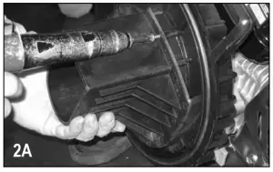
Remove the check valve (12705) from the volute (13702). Remove the one upper volute screw (12900) and the two smaller volute screws (12725) from the volute. Remove the volute from the remaining pump assembly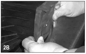
Remove the impeller bolt (12765A) from the impeller (12771A/12772). Remove the impeller bolt gasket (12774VA) from the impeller.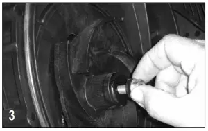
Screw the supplied 7/16-14 hex head cap screw into the impeller snout. As the bolt is tightened the impeller will be pried off of the shaft of the drive unit. Remove the 7/16-14 screw once the impeller has been removed from the drive unit. 4B: If the pump impeller is going to be reused the ceramic seal half (12713) should be removed from the impeller at this time. The impeller key (12902A) located behind the ceramic seal half should be replaced at this time also.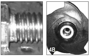
Remove the four bracket screws (12715A), rear bracket washers (12901), and screw head O-rings (12717) from the rear bracket using a ½″ socket. With the four bracket screws removed, the rear bracket can now be removed from the drive unit.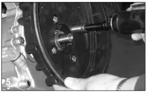
Remove carbon seal half from rear bracket with a round object. Tap gently with a hammer. Take care not to crack seal if reusing. Once disassembled; clean all reusable parts thoroughly, removing any traces of old gasket material and trapped / dried liquids from pump.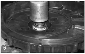
At this time, it may be necessary to polish the drive unit shaft to remove any corrosion that may have formed.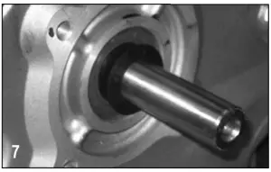
ASSEMBLY INSTRUCTIONS
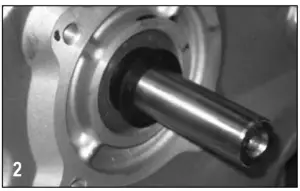
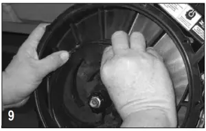
Install the pump slinger (12706) on to the drive unit shaft. The slinger should be slid all the way back on the shaft of the drive unit so that the slinger covers the step on the drive unit shaft as shown.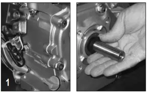
Place the seal O-ring (12710) behind the lip of the carbon seal half.
To install the carbon seal (12713) half into the rear bracket use a tool such as a 1 ½″ pipe nipple or arbor press to give even pressure on the metal flange of the seal housing during installation. Gently press the seal into position until it bottoms.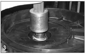
Clean the threads of the bracket screws (12715A) thoroughly. Once clean, install the four flat washers (12901) and four screw head O-rings (12717) onto each of the bracket screws.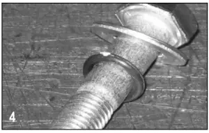
Install the rear bracket onto the drive unit using the bracket screw assemblies from the previous step. The handle of the rear bracket should be to the top of the drive unit. Tighten the screws securely.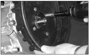
Verify impeller hex nut (12775A) is located at the bottom of impeller snout (should be installed). A very light press fit may be required to install nut into cavity. Install the ceramic seal half into hub of impeller by using an arbor press or similar tool. Outside diameter of rubber boot may be sparingly coated with silicone to ease installation.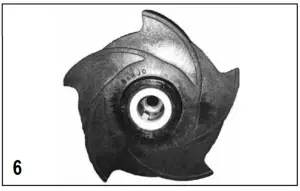
Place the impeller key (12902A) in the slot located inside the impeller snout. The impeller (12771A/12772/13772) is now ready to be slid onto the drive unit shaft.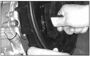
Secure the impeller to the drive unit shaft with the impeller bolt gasket (12774VA) and impeller bolt (12765A). Tighten the impeller bolt until snug.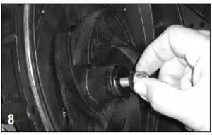
Install the O-ring segment (12754) onto the rear bracket as shown.
Install volute (12702A/13702) onto rear bracket using the three volute screws (12900/12725). Install check valve (12705) onto the snout of the volute. Drive unit should be turned over a few times to check for clearance between the two. A small amount of drag between impeller and volute is ok, however, if the drive unit will not turn over because of the lack of clearance, a bracket shim may have to be used.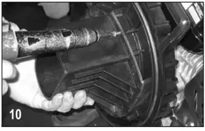
Place the pump body O-ring (12719A) around the outside flange of the rear bracket. The O-ring may be sparingly lubricated with silicone to ease installation of the pump body in the next step.
Install the pump body (12712/13712) as shown below with the outlet flange facing up. Install the 10 body screws (12720), 10 lock washers (V07018), and 10 nuts (V07019) to secure the pump body to the rear bracket. Tighten the bolts securely all the way around.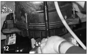
Please see banjocorp.com for more information
 report this ad
BANJO CORPORATIONA Unit of IDEX Corporation 150 Banjo DriveCrawfordsville, IN 47933 U.S.A.Telephone: (765) 362-7367Tech Sales: (888) 705-7020Fax: (765) 362-0744banjocorp.com
References
[xyz-ips snippet=”download-snippet”]