 Instruction Manual
 Instruction Manual
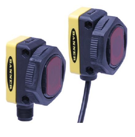
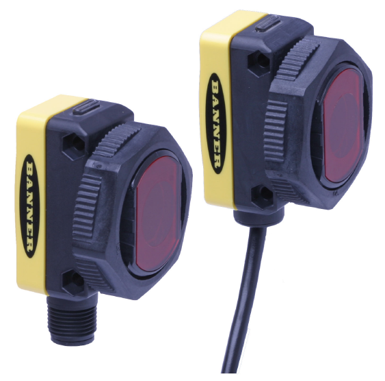
- Advanced one-piece photoelectric sensors with exceptional long-range optical performance
- Compact housing with mounting versatility, via its popular 30 mm threaded barrel or side-mount holes
- 10 V DC to 30 V DC operation with bipolar discrete outputs, NPN and PNP
- Selectable Light or Dark Operate, depending on wiring
- Tough ABS/polycarbonate blend housing is rated to IEC IP67; NEMA 6
- Easy-to-see sensor status indicators: two status LEDs visible from 360°; extra-large Output indicator on back of sensor housing (except emitters) visible from long distance
- Opposed, retroreflective, polarized retroreflective, diffuse and fixed-field (200 mm, 400 mm, or 600 mm cutoff) models available
- Retroreflective, polarized retroreflective, and diffuse models have potentiometer on back of housing for easy sensor range adjustment
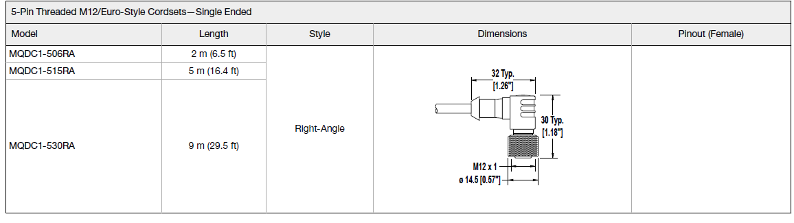
- Choose 2 m integral cable or M12/Euro-style integral QD models
WARNING: Not To Be Used for Personnel ProtectionNever use this device as a sensing device for personnel protection. Doing so could lead to serious injury or death. This device does not include the self-checking redundant circuitry necessary to allow its use in personnel safety applications. A sensor failure or malfunction can cause either an energized or de-energized sensor output condition.
Models
| Model 1 | Sensing Mode | Beam | Range 2 | Output |
| QS30E (emitter) |
Opposed |
875 nm Infrared |
60 m (200 ft) |
N/A |
| QS30R (receiver) | Effective Beam: 18 mm (0.7 in) |
Bipolar NPN/PNP |
||
| QS30LP | Polarized Retroreflective | 630 nm Visible Red | 8 m (26 ft) | |
| QS30LV | Retroreflective | 12 m (40 ft) | ||
| QS30D | Diffuse | 940 nm Infrared | 1 m (3.3 ft) | |
| QS30FF200 |
Fixed Field |
680 nm Visible Red |
200 mm (8 in) | |
| QS30FF400 | 400 mm (16 in) | |||
| QS30FF600 | 600 mm (24 in) |
Fixed-Field Mode Overview
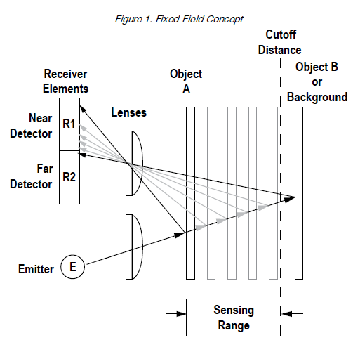
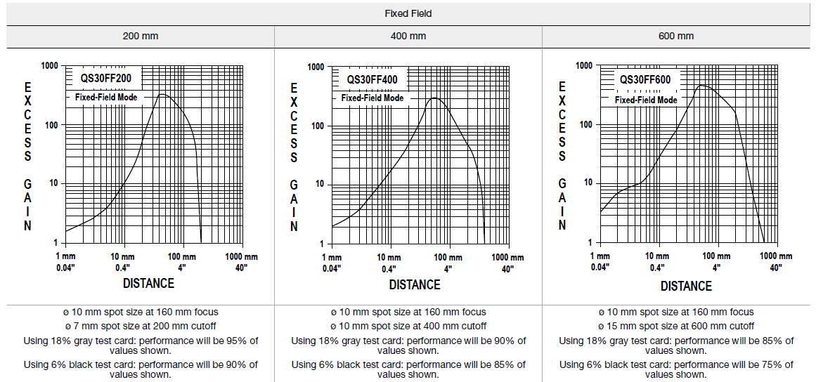
QS30 self-contained fixed-field sensors are small, powerful, visible red diffuse mode sensors with far-limit cutoff (a type of background suppression). Their high excess gain and fixed-field technology allow detection of objects of low reflectivity, while ignoring background surfaces. The cutoff distance is fixed. Backgrounds and background objects must always be placed beyond the cutoff distance.
Fixed-Field Sensing – Theory of Operation
The WORLD-BEAM QS30 Series Sensor compares the reflections of its emitted light beam (E) from an object back to the sensor’s two differently aimed detectors, R1 and R2. See Figure 1 on p. 2. If the near detector’s (R1) light signal is stronger than the far detector’s (R2) light signal (see object A in the Figure below, closer than the cutoff distance), the sensor responds to the object. If the far detector’s (R2) light signal is stronger than the near detector’s (R1) light signal (see object B in the Figure below, beyond the cutoff distance), the sensor ignores the object. The cutoff distance for the QS30 is fixed at 200 mm, 400 mm, or 600 mm (8 in, 16 in, or 24 in). Objects lying beyond the cutoff distance are usually ignored, even if they are highly reflective. However, under certain conditions, it is possible to falsely detect a background object (see Background Reflectivity and Placement on p. 2).
- Only standard 2 m (6.5 ft) cabled models are listed.
- To order the 9 m (30 ft) integral cable model, add suffix “W/30” to the model number (for example, QS30E W/30).
- To order the 5-pin integral M12/Euro-style quick disconnect (QD), add suffix “Q” (for example, QS30EQ).
- Polarized Retroreflective and Retroreflective ranges are specified using a model BRT-84 retroreflector.
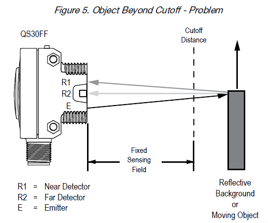
In the drawings and information provided in this document, the letters E, R1, and R2 identify how the sensor’s three optical elements (Emitter “E”, Near Detector “R1”, and Far Detector “R2”) line up across the face of the sensor. The location of these elements defines the sensing axis, see Figure 2 on p. 2. The sensing axis becomes important in certain situations, such as those illustrated in Figure 5 on p. 3 and Figure 6 on p. 3.
Configuring a Sensor
Sensing ReliabilityFor highest sensitivity, position the target for sensing at or near the point of maximum excess gain. Refer to the Performance Curves for the excess gain. Sensing at or near this distance makes the maximum use of each sensor’s available sensing power. The background must be placed beyond the cutoff distance. Note that the reflectivity of the background surface also may affect the cutoff distance. Following these guidelines improves sensing reliability.
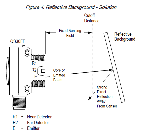
Background Reflectivity and Placement
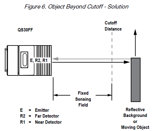
Avoid mirror-like backgrounds that produce specular reflections. A false sensor response occurs if a background surface reflects the sensor’s light more to the near detector (R1) than to the far detector (R2). The result is a false ON condition (Figure 3 on p. 2). Correct this problem by using a diffusely reflective (matte) background, or angling either the sensor or the background (in any plane) so the background does not reflect light back to the sensor (Figure 4 on p. 2). Position the background as far beyond the cutoff distance as possible.An object beyond the cutoff distance, either stationary (and when positioned as shown in Figure 5 on p. 3), or moving past the face of the sensor in a direction perpendicular to the sensing axis, may cause unwanted triggering of the sensor if more light is reflected to the near detector than to the far detector. Correct the problem by rotating the sensor 90° (Figure 6 on p. 3). The object then reflects the R1 and R2 fields equally, resulting in no false triggering. A better solution, if possible, may be to reposition the object or the sensor.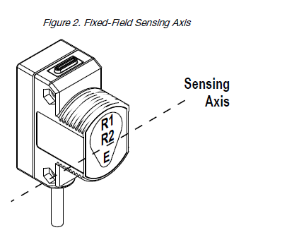
Color Sensitivity
The effects of object reflectivity on cutoff distance, though small, may be important for some applications. It is expected that at any given cutoff setting, the actual cutoff distance for lower reflectance targets is slightly shorter than for higher reflectance targets. This behavior is known as color sensitivity.
For example, an excess gain of 1 for an object that reflects 1/10 as much light as the 90% white card is represented by the horizontal graph line at excess gain = 10. An object of this reflectivity results in a far limit cutoff of approximately 190 mm (7.5 in) cutoff model, for example; and 190 m (7.5 in) represents the cutoff for this sensor and target. These excess gain curves were generated using a white test card of 90% reflectance. Objects with reflectivity of less than 90% reflect less light back to the sensor, and thus require proportionately more excess gain in order to be sensed with the same reliability as more reflective objects. When sensing an object of very low reflectivity, it may be especially important to sense it at or near the distance of maximum excess gain.
Wiring Diagrams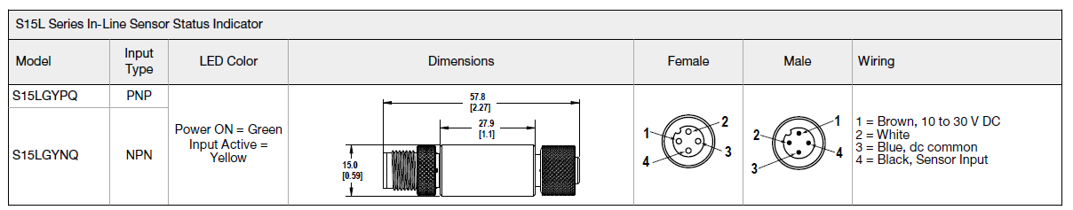
Cabled wiring diagrams are shown. Quick disconnect wiring diagrams are functionally identical.
Specifications
Supply Voltage10 V DC to 30 V DC (10% max. ripple) at less than 40 mA, exclusive of load Protected against reverse polarity and transient voltagesOutput ResponseOpposed Mode: 5 milliseconds ON and OFF All others: 2 millisecondsNOTE: 100 millisecond delay on power-up; outputs do not conduct during this timeRepeatabilityOpposed Mode: not applicableAll others: 500 microsecondsCutoff Point ToleranceFixed-Field only: ± 5% of nominal cutoff distanceConstruction and MountingABS housing, rated IEC IP67; NEMA 6; Acrylic lens cover 3 mm mounting hardware includedConnections2 m (6.5 ft) unterminated 5-wire PVC cable; 9 m (30 ft) unterminated 5-wire PVC cable ; or Integral 5-pin M12/Euro-style male quick disconnectApplication Tip for the QS30LV ModelFor best sensing reliability, targets should be a minimum of 0.5m from the sensorOutput ConfigurationBipolar: One current sourcing and one current sinkingRating: 100 mA maximum each output at 25 °COff-state leakage current:NPN: less than 200 μAPNP: less than 10 μAON-state saturation voltage:NPN: less than 1.6 V at 100 mAPNP: less than 2.0 V at 100 mAProtected against false pulse on power-up and continuous overload or short circuit of outputsAdjustmentsSelectable Light/Dark Operate is achieved via the gray wire.Opposed, Retroreflective, and Polarized Retroreflective models:Light Operate – Low (0 V to 3 V)*Dark Operate – High (open or 5 V to 30 V)*Diffuse and Fixed-Field models:Light Operate – High (open or 5 V to 30 V)*Dark Operate – Low (0 V to 3 V)*Diffuse, Retroreflective, and Polarized Retroreflective mode models (only):Single-turn Sensitivity (Gain) adjustment potentiometer * Input impedance 10 kΩ
Indicators2 LEDs on sensor top:
| Green | Yellow | |
| On | Power on | Light sensed |
| Flashing | Output overloaded (except receivers) | Marginal excess gain (1–1.5× excess gain) |
Operating Conditions–20 °C to +70 °C (–4 °F to +158 °F) 95% at +50 °C maximum relative humidity (non-condensing)Large oval LED on sensor back (except emitters): Yellow on indicates the output is conducting
Vibration and Mechanical Shock
All models meet MIL-STD-202F, Method 201A (Vibration: 10 Hz to 60 Hz maximum, 0.06 inch (1.52 mm) double amplitude, 10G maximum acceleration) requirements. Also meets IEC 60947-5-2 (Shock: 30G 11 ms duration, half sine wave) requirements. Certifications Pending
Performance CurvesFor the diffuse models, the performance is based on using a 90% reflectance white test card.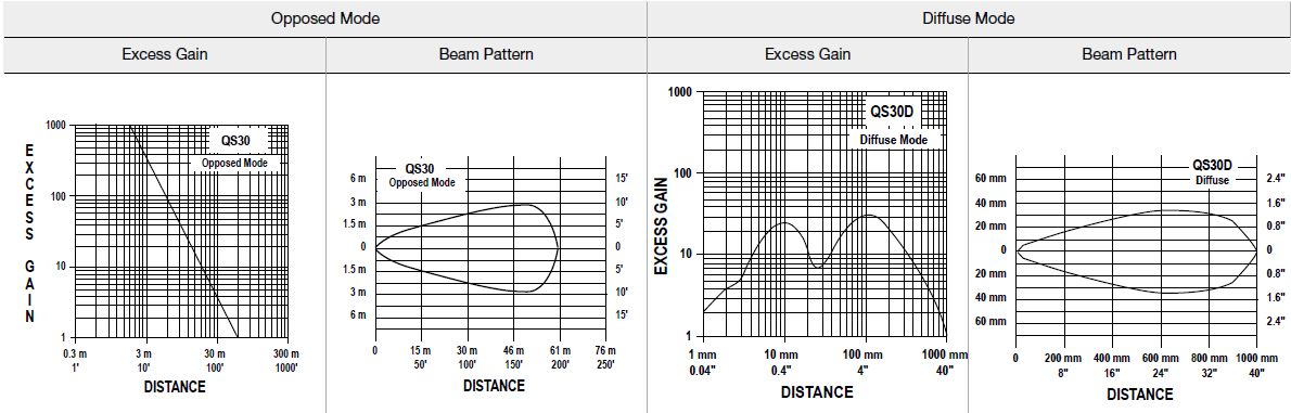 For the polarized retroreflective and retroreflective models, the performance is based on using the specified retroreflector.
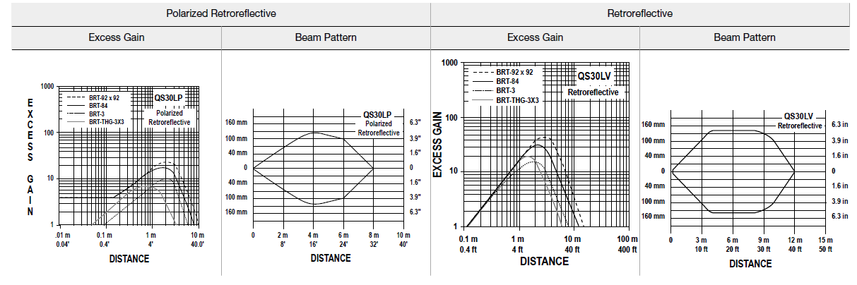 Fixed field performance is based on using a 90% reflectance white test card.
 Dimensions
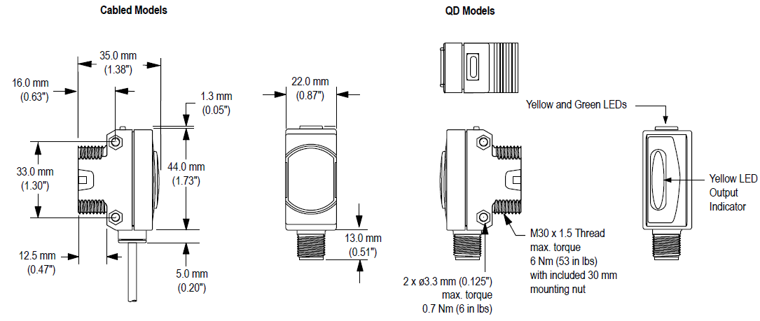
All measurements are listed in millimeters [inches], unless noted otherwise.
Accessories
Quick-Disconnect Cables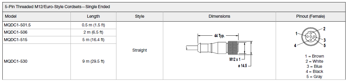
Sensor Status Indicators
Brackets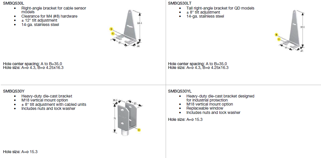
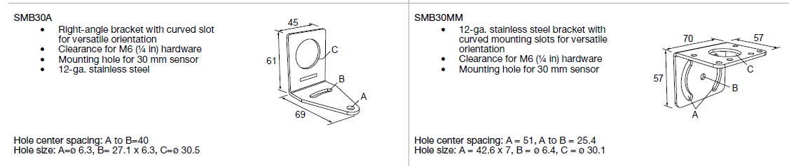
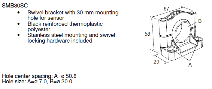
All measurements are listed in millimeters [inches], unless noted otherwise.
AperturesOpposed-mode QS30 sensors may be fitted with apertures to narrow or shape the sensor’s effective beam to more closely match the size or profile of the objects being sensed. A common example is the use of “line” (or “slot”) type apertures to sense thread.Note: The use of apertures reduces the sensing range.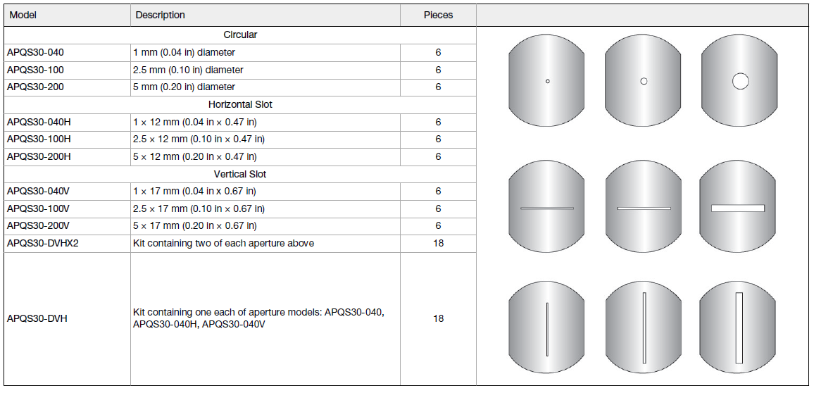
Reduced Range for QS30E and QS30R Pair with Apertures
| Aperture Model | Maximum Range | |
| Aperture on Both Emitter and Receiver | Aperture on Receiver Only | |
| APQS30-040 | 0.5 m (1.5 ft) | 4.1 m (13.5 ft) |
| APQS30-100 | 2.4 m (8 ft) | 14.3 m (47 ft) |
| APQS30-200 | 11.6 m (38 ft) | 23.5 m (77 ft) |
| APQS30-040H | 7 m (23 ft) | 16.8 m (23 ft) |
| APQS30-100H | 16.5 m (54 ft) | 24.7 m (54 ft) |
| APQS30-200H | 28.7 m (94 ft) | 36.6 m (94 ft) |
| APQS30-040V | 7 m (23 ft) | 16.8 m (23 ft) |
| APQS30-100V | 16.5 m (54 ft) | 24.7 m (54 ft) |
| APQS30-200V | 28.7 m (94 ft) | 36.6 m (94 ft) |
Example: The QS30E/QS30R sensor pair is used with apertures APQS30-040. Using the circular aperture on only the receiver, the range reduces to 4.1 m (13.5 ft). When the APQS30-040 aperture is installed on both the receiver and emitter, the sensor range reduces to 0.5 m (1.5 ft).
Retroreflective TargetsBanner offers a wide selection of high-quality retroreflective targets. See www.bannerengineering.com for complete information.Note: Polarized sensors require corner cube type retroreflective targets. Non-polarized sensors may use any retroreflective target.
 report this ad
Banner Engineering Corp. warrants its products to be free from defects in material and workmanship for one year following the date of shipment. Banner Engineering Corp. will repair or replace, free of charge, any product of its manufacture which, at the time it is returned to the factory, is found to have been defective during the warranty period. This warranty does not cover damage or liability for misuse, abuse, or the improper application or installation of the Banner product. THIS LIMITED WARRANTY IS EXCLUSIVE AND IN LIEU OF ALL OTHER WARRANTIES WHETHER EXPRESS OR IMPLIED (INCLUDING, WITHOUT LIMITATION, ANY WARRANTY OF MERCHANTABILITY OR FITNESS FOR A PARTICULAR PURPOSE), AND WHETHER ARISING UNDER COURSE OF PERFORMANCE, COURSE OF DEALING OR TRADE USAGE. This Warranty is exclusive and limited to repair or, at the discretion of Banner Engineering Corp., replacement. IN NO EVENT SHALL BANNER ENGINEERING CORP. BE LIABLE TO BUYER OR ANY OTHER PERSON OR ENTITY FOR ANY EXTRA COSTS, EXPENSES, LOSSES, LOSS OF PROFITS, OR ANY INCIDENTAL, CONSEQUENTIAL OR SPECIAL DAMAGES RESULTING FROM ANY PRODUCT DEFECT OR FROM THE USE OR INABILITY TO USE THE PRODUCT, WHETHER ARISING IN CONTRACT OR WARRANTY, STATUTE, TORT, STRICT LIABILITY, NEGLIGENCE, OR OTHERWISE. Banner Engineering Corp. reserves the right to change, modify or improve the design of the product without assuming any obligations or liabilities relating to any product previously manufactured by Banner Engineering Corp. Any misuse, abuse, or improper application or installation of this product or use of the product for personal protection applications when the product is identified as not intended for such purposes will void the product warranty. Any modifications to this product without prior express approval by Banner Engineering Corp will void the product warranties. All specifications published in this document are subject to change; Banner reserves the right to modify product specifications or update documentation at any time. Specifications and product information in English supersede that which is provided in any other language. For the most recent version of any documentation, refer to: www.bannerengineering.com.![]()
References
[xyz-ips snippet=”download-snippet”]