
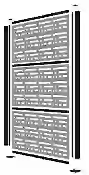
Barrettee 73040779 Outdoor Living Matte Black Decorative Screen
To register your product, please visit: barretteoutdoorliving.com
WARNING:
- Improper installation of this product can result in personal injury. Always wear safety goggles when cutting, drilling and assembling the product.
- Incorrect installation may cause harm to the product or individual.
- Check local building codes to determine pool-safe product options.
NOTICE:
- DO NOT attempt to assemble the kit if parts are missing or damaged.
- DO NOT return the product to the store. For assistance or replacement parts call: 1-800-336-2383.
BEFORE YOU BEGIN:
Check your local zoning laws.
- Local zoning laws and Home Owners Associations may regulate the location, style and height of your product or even require a permit signoff beforehand.
- Check local codes for frost line depth and regulations.
- Additional products and assembly may be required to meet wind code requirements. Notice of acceptance (NOA) can be found at www.miamidade.gov/building/pc-search_app.asp
Contact your local utilities companies.
- You must have the utility companies clearly mark your property for electrical, gas or water lines to avoid puncturing any unseen underground utilities.
- NOTE: Installation is best accomplished with two sets of hands.
TOOLS/MATERIALS NEEDED:
- Drill
- Pencil
- Tape Measure
- Rubber Mallet
- 3″ Spacer Blocks
- Level
SOLD SEPARATELY:
- (3) 2×4 Decorative Screen Panels
- 3/8″ Bolts/Screws (For surface mounting)

To obtain and review a copy of the warranty please visit barretteoutdoorliving.comYou may also contact us at 1-800-336 2383 or email [email protected]
- Determine where you would like to install the frame kit. Make sure the posts will be held in place by a solid structure and if necessary, reinforce the surface it is attaching to.

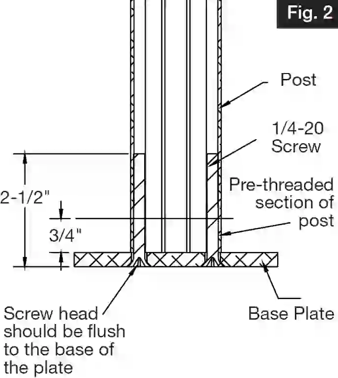
- Install base plates to bottom of posts. Locate bottom post with pre-tapped holes and attach the bottom plate to that end. Using a #3 Phillips drive bit, screw base plate to bottom of post through the (4) screw bosses (Fig. 1). Posts are partially threaded on one end of the post (3/4″). While installing screws, you will feel resistance at the 3/4″ mark for a tighter, more secure fi t. Install screws until they’re flush with the plate (Fig. 2).TIP: Drill should be set to low speed when securing plates to post.
- Set first post in desired location. Use the post assembly to mark the holes for the surface mounting plate. Mark and drill holes for appropriate 3/8″ fasteners (fasteners will vary depending on mounting surface).Attach post/base assembly to surface using appropriate 3/8″ fasteners.NOTE: Keep in mind ceiling clearance if installing inside. Attaching post/base assembly to surface may need to wait until end of installation if full assembly must be tilted for all 3 panels to be installed properly.
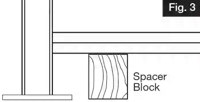
- Place two 3″ spacer blocks to support bottom rail. Take bottom rail and insert into channel or first post, resting on the 3″ spacer blocks (Fig. 3).NOTE: This step is to set distance in between posts.
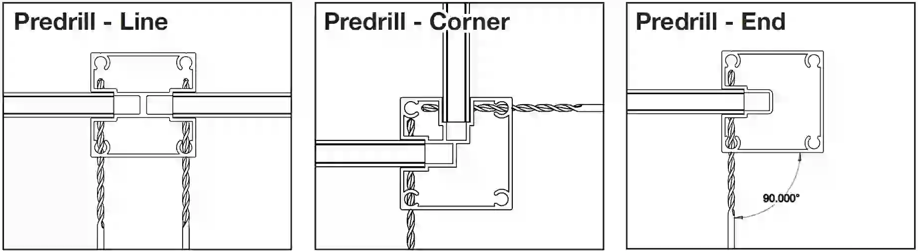
- Take second post and insert opposite side of bottom rail into the channel of this post. Be sure rail is fully inserted into the post. Lock second post into position by repeating Step 3.NOTE: If connecting more than one frame kit together, line or corner posts are available (sold separately).
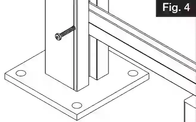
- Locate where to pre-drill a hole through the post and rail (Fig. 4). Pilot holes for screws should be located directly at the intersection of the small groove of the post and the channels. Using the 1/8″ drill bit provided, pre-drill pilot hole as indicated above.Then, using the #2 square drive bit provided in the kit, secure screw into both posts, securing posts and rails together. (Fig. 5). Remove 3″ spacer blocks.
- Install screen by sliding down the channels on either side of the posts (Fig. 6) and into the channel of the bottom rail.NOTE: The screen will be loose in the posts and the bottom rail. This is designed to allow the screen to expand and contract during heating and cooling of the day.
- Slide H-Channel in the groove from the top, resting it on the top of the Decorative Screen Panel. Lift H-Channel about 1/8″ (to allow for expansion and contraction), then pre-drill a hole following same process in Step 6. Screw should be installed directly on the small groove of the post, connecting with the H-channel. (Fig. 7).
- Repeat steps 7 & 8 for the middle and top panel (Fig. 8).NOTE: Always use a tape measure to verify rails are equal space from each other and that they are level.
- Place post caps on top of posts (lining up the tabs underneath to the holes in the post). Using a rubber mallet, fully seat the cap onto the post (Fig. 9).NOTE: If installing additional frame kits (line or corner), install these prior to placing post caps on posts.
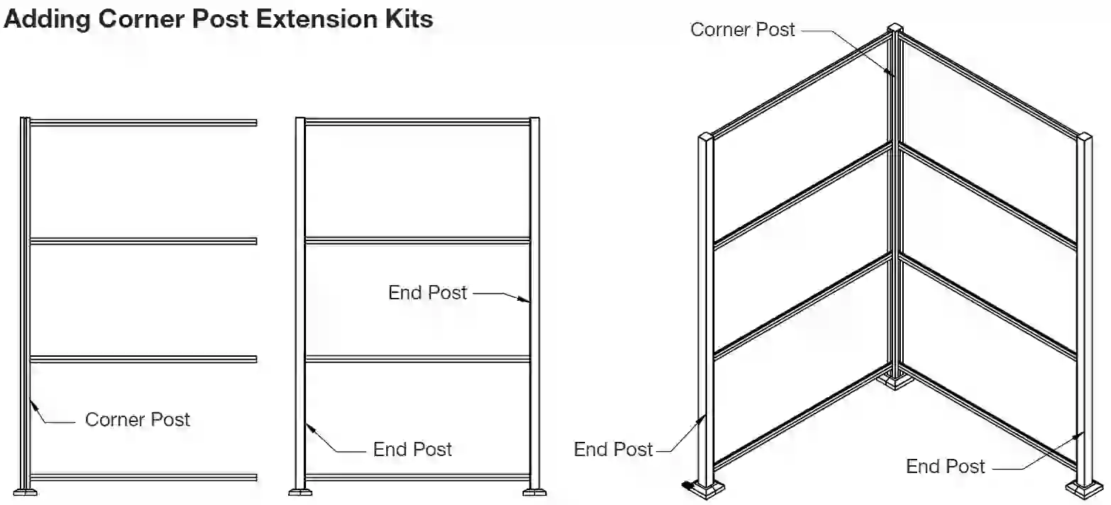
- To connect additional frame kits, line and corner extension kits are available.
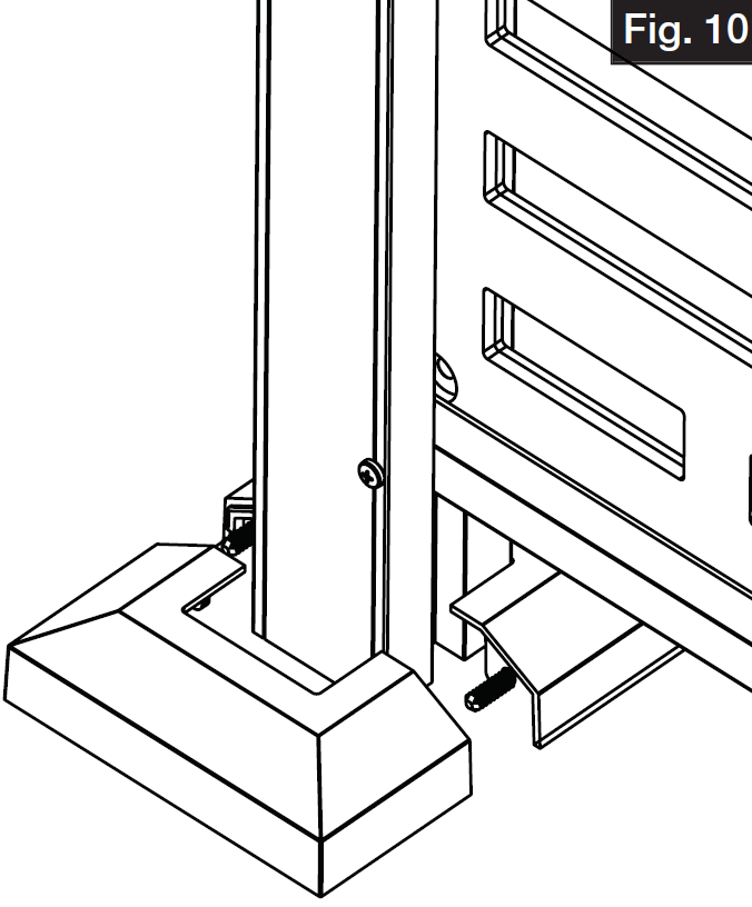
- Assemble trim ring over plate. Take one side of trim ring and push plugs through holes underneath. Take second half of the trim ring and push together (Fig. 10).

 Then, using the #2 square drive bit provided in the kit, secure screw into both posts, securing posts and rails together. (Fig. 5). Remove 3″ spacer blocks.
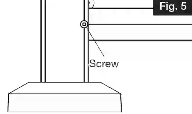


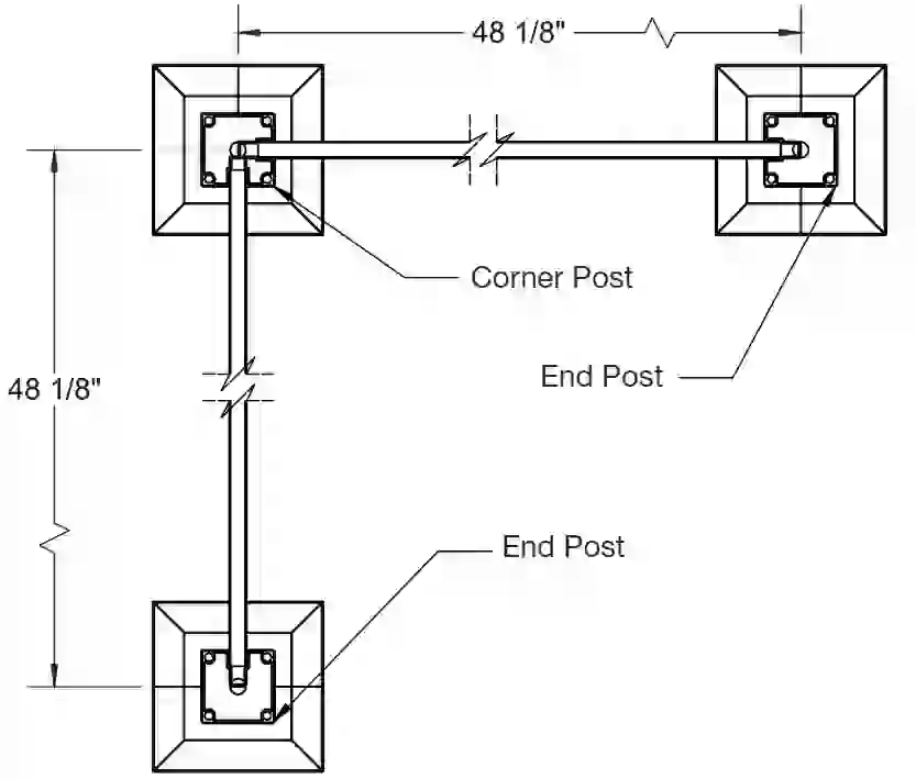
Adding Line Post Extension Kits

Adding Corner Post Extension Kits
![]()
References
[xyz-ips snippet=”download-snippet”]